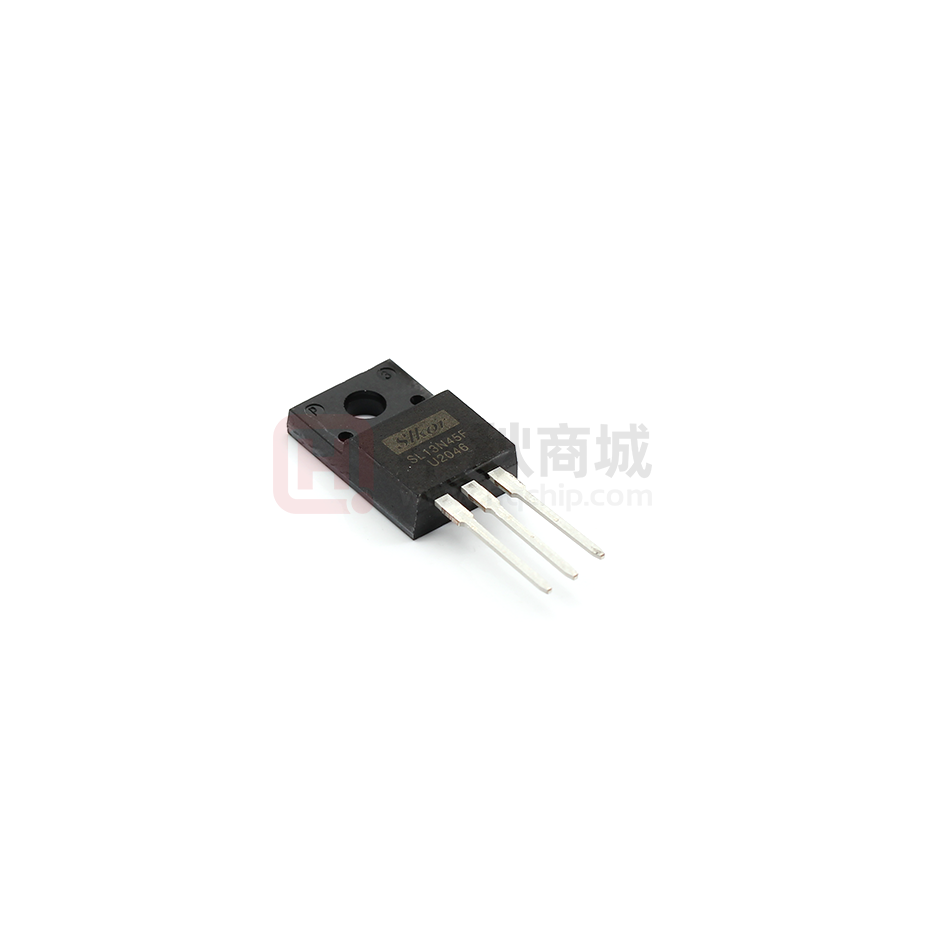
SL13N45F
N-Channel Power MOSFET
●Features:
■ 13.0A, 450V, RDS(on)(Typ) =0.47Ω@VGS=10V
■ Low Gate Charge
■ Low Crss
■ 100% Avalanche Tested
■ Fast Switching
■ Improved dv/dt Capability
●Application:
■ High Frequency Switching Mode Power Supply
■ Active Power Factor Correction
Schematic diagram
TO-220F
se noted)
Absolute Maximum Ratings(Tc=25C unless otherwise
Symbol
Parameter
VDSS
ID
IDM
Drain-Source Voltage
Drain Current
Drain Current
- Continuous(Tc=25C)
- Continuous(Tc=100C)
-Pulsed
(Note1)
Value
Unit
450
V
13.0*
A
8.6*
A
44*
A
±25
V
VGSS
Gate-Source Voltage
EAS
Single Pulsed Avalanche Energy
(Note2)
360
mJ
IAR
Avalanche Current
(Note1)
13.0
A
EAR
Repetitive Avalanche Energy
(Note1)
19.5
mJ
dv/dt
Peak Diode Recovery dv/dt
(Note3)
4.5
V/ns
PD
Power Dissipation(TC =25C)
-Derate above 25°C
39
W
0.4
W/C
Tj
Operating Junction Temperature
150
C
-55 to+150
C
Max
Unit
Tstg
Storage Temperature Range
* Drain Current Limited by Maximum Junction Temperature.
Thermal Characteristics
Symbol
Parameter
RθJC
Thermal Resistance,Junction to Case
3.15
C /W
RθJA
Thermal Resistance,Junction to Ambient
62.5
C /W
www.slkormicro.com
1
�SL13N45F
Electrical Characteristics(Tc=25C unless otherwise noted)
Symbol
Parameter
Test Conditons
Off Characteristics
BVDSS Drain-source Breakdown Voltage VGS=0V ,ID=250μA
△BVDSS
/△TJ
Breakdown Voltage Temperature
Coefficient
IDSS
Zero Gate Voltage Drain Current
Gate-Body Leakage Current,Forward
IGSSF
Gate-Body Leakage Current,Reverse
IGSSR
On Characteristics
VGS(th) Gate Threshold Voltage
RDS(on) Static Drain-Source On-Resistance
gFS
Forward Transconductance
ID=250μA
(Referenced to 25C)
VDS=450V,VGS=0V
VDS=320V,Tc=125C
VGS=+20V, VDS=0V
VGS=-20V, VDS=0V
VDS= VGS, ID=250μA
VGS=10 V, ID=5.5A
VDS=40 V, ID=5.5A
(Note4)
Dynamic Characteristics
Input Capacitance
Ciss
VDS=25V,VGS=0V,
Output Capacitance
Coss
f=1.0MHz
Reverse Transfer Capacitance
Crss
Switching Characteristics
Turn-On Delay Time
td(on)
Turn-On Rise Time
tr
VDD = 200 V, ID = 13.0A,
RG = 20 Ω (Note4,5)
Turn-Off Delay Time
td(off)
Turn-Off Fall Time
tf
Total Gate Charge
Qg
VDS = 320 V, ID =13.0 A,
Gate-Source Charge
Qgs
VGS = 10 V (Note4,5)
Gate-Drain Charge
Qgd
Drain-Source Diode Characteristics and Maximum Ratings
Maximum Continuous Drain-Source Diode Forward Current
IS
Maximum Pulsed Drain-Source Diode Forward Current
ISM
Drain-Source Diode Forward Voltage VGS =0V,IS=13.0A
VSD
Reverse Recovery Time
trr
VGS =0V, IS=13.0A,
d IF /dt=100A/μs (Note4)
Reverse Recovery Charge
Qrr
Notes:
1、Repetitive Rating:Pulse Width Limited by Maximum Junction Temperature.
2、L = 5mH, IAS =13.0A, VDD = 50V, RG = 25 Ω, Starting TJ = 25C.
3、ISD≤13.0A, di/dt≤100A/μs, VDD≤BVDSS, Starting TJ = 25C.
4、Pulse Test : Pulse Width ≤300 µ s, Duty Cycle≤2%.
5、Essentially Independent of Operating Temperature.
www.slkormicro.com
2
Min
Typ
Max
Unit
450
--
--
V
--
0.40
--
V/C
-----
-----
1
10
10
μA
μA
nA
nA
2.0
--
-10
-4.0
0.47 0.49
V
Ω
--
8
--
S
----
970
150
2.8
----
pF
pF
pF
--------
33
31
83
56
15
4.6
4.5
--------
ns
ns
ns
ns
nC
nC
nC
------
---430
3.8
13.0
44
1.4
---
A
A
V
ns
μC
�SL13N45F
On-Regin Characteristics
Transfer Characteristics
On-Resistance Variation vs.
Drain Current and Gate Voltage
Body Diode Forward Voltage Variation
vs. Source Current and Temperature
Capacitance Characteristics
www.slkormicro.com
Gate Charge Characteristics
3
�SL13N45F
Breakdown Voltage Variation
vs. Temperature
On-Resistance Variation
vs. Temperature
Maximum Drain Current
Vs. Case Temperature
Maximum Safe Operating Area
www.slkormicro.com
4
�SL13N45F
TO-220F Package Dimensions
SYMBOL
A
A1
A2
A3
B1
B2
B3
C
C1
C2
www.slkormicro.com
min
9.80
2.90
9.10
15.40
4.35
6.00
3.00
15.00
8.80
nom
7.00
max
10.60
SYMBOL
D
D1
D2
D3
E
E1
E2
E3
E4
α
3.40
9.90
16.40
4.95
7.40
3.70
17.00
10.80
5
min
1.15
0.60
0.20
2.24
nom
2.54
0.70
UNIT:mm
max
1.55
1.00
0.50
2.84
1.0×45°
0.35
2.30
30°
0.65
3.30
�
很抱歉,暂时无法提供与“SL13N45F”相匹配的价格&库存,您可以联系我们找货
免费人工找货- 国内价格
- 1+1.62000
- 10+1.56000
- 100+1.41600
- 500+1.34400
