| H25 SERIES
INCREMENTAL ENCODER
Introduction
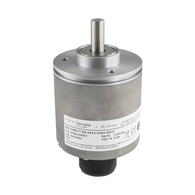
The H25 is the flagship of the BEI Sensors product line. It was designed from the ground up for the industrial marketplace. The H25 offers features
such as EMI shielding, high precision ball bearings and matched thermal coefficients on critical components. The encoder meets up to IP66 sealing
requirements when ordered with the shaft seal.
Features
• Wide operating temperature range
• Ruggedized, well-sealed unit for long life operation
• Industry standard interfaces make it easy to install
• Extensive electrical protection reduces damage due to miswiring
• High noise immunity especially useful in electrically noisy
automation environments
• Selected configurations available in 1 to 3 days shipment (“Express
Encoder” option)
For Generation 1
datasheet click here.
Applications
• Machine control – speed and position
• From wood harvesting all the way to processed lumber
• Oil well logging – wireline and coil tubing
• Agricultural equipment - center point irrigation, planting, harvesting
• Web process control - dancers, slitters, flying knives
• Food processing – inspection stations, conveyor control.
SPECIFICATIONS
Mechanical
Shaft Diameter
3/8” standard (1/4” as special feature)
Flat On Shaft
3/8” Shaft: 0.75 long X 0.03” deep, 1/4” shaft 0.75 X .02 deep
Shaft Loading
3/8” shaft: Up to 40 pounds axial and 35 pounds radial
Shaft Runout
0.0005 T.I.R. at midpoint regardless of shaft diameter
Starting Torque at 25°C
1.0 in-oz max without shaft seal; 2.5 in-oz max with shaft seal.
Bearings
High precision ball bearings, Material: Chrome steel; shielded bearings standard, sealed bearings
optional
Shaft Material
Stainless Steel
Bearing Housing
Die cast aluminum with protective finish
Cover
Die cast aluminum with protective finish
Bearing Life
2 X 10⁸ revs (1300 hrs at 2500 RPM) at rated load, 1 X 10¹⁰ revs (67,000 hrs at 2500 RPM) at
10% of rated load
Maximum RPM
10,000 RPM nominal, 8000 RPM with 1/2” shaft (see Frequency Response, below)
Moment of Inertia
4.1 X 10⁻⁴ oz-in-sec2
Weight
13 oz typical
Page 1
Copyright © 2021 Sensata Technologies, Inc.
www.sensata.com
�Electrical
Code
Incremental
Output Format
2 outputs in quadrature, A leads B CCW, 1/2 cycle index , Z, gated with negative B
Consult factory for other output formats.
Cycles per Shaft Turn
2 to 80,000 (see table 2)
Supply Voltage
5 to 28 VDC +/- 5%
Current Requirements
100 mA typical +output load, 250 mA (max)
Voltage/Output
(See notes)
15/V: Line Driver, 5–15 VDC in, Vout = Vin
28/V: Line Driver, 5–28 VDC in, Vout = Vin
28/5: Line Driver, 5–28 VDC in, Vout = 5 VDC
28/O: Open Collector, 5–28 VDC in, OCout
Protection Level
Reverse, overvoltage and line driver output protection diodes
Frequency Response
300 kHz
Output Terminations
See Table 1
Environmental
Enclosure Rating
IP66 when ordered with shaft seal (on units with an MS connector) or a cable gland (on units with cable
termination).
Temperature
Standard operating temperature -40° C to +85° C;
options available at -40° C to +100° C (Consult factory).
Storage temperature -40° C to +100° C.
Shock
100 g’s for 5 msec duration
Vibration
50 to 2000 Hz @ 30grms
Humidity
98% RH without condensation
Page 2
Copyright © 2021 Sensata Technologies, Inc.
www.sensata.com
�DIMENSIONS
Dimensions in inches
H25D SQUARE FLANGE
(WITH STANDARD 3/8" SHAFT AND SM18 CONN.)
2.66
SM18 OPTION
A
A
2.50
1.79
1.18
0.26
0.30
0.88
1.2500
1.2495
0.3747
0.3743
4XR0.21
0.34
SHAFT FLAT
30°
4X 0.22
THRU
3XR 1.30
2.50
30°
30°
2.63
2.064
VIEW A-A
D FLANGE
COVER BOSS DETAILS
SCALE 1 : 2.5
H25E SERVO MOUNT
H25G SERVO MOUNT
(WITH OPTIONAL F2 FACEMOUNT)
(WITH OPTIONAL F1 FACEMOUNT)
SM18 OPTION
2.50
2.28
1.18
3XR0.15
0.88
0.10
SM18 OPTION
2.50
0.10
0.30
1.2500
1.2495
1.79
1.79
0.13
0.88
4X#4-40X.25 DP
EQUALLY SPACED
0.13
45°
1.272 B.C.
3X#10-32X.25 DP
EQUALLY SPACED
2.50
1.875 B.C.
2.500
2.498
2.625
Page 3
Copyright © 2021 Sensata Technologies, Inc.
www.sensata.com
�CONNECTOR OPTIONS
FACEMOUNT OPTIONS
(NOTE RESTRICTIONS)
EM18
F1
0.90
3X#10-32X.25 DP
EQUALLY SPACED
2.66
SM18
2.50
2.50
1.79
1.875 B.C.
F2
(Available only on G housing)
EM16
0.69
4X#4-40X.25 DP
EQUALLY SPACED
SM16
1.97
2.50
2.50
1.79
0.45
0.90
F3
EM12
0.49
4X#4-40X.25 DP
EQUALLY SPACED
SM12
1.77
2.50
2.50
1.79
2.000 B.C.
F4
4X#6-32X.25 DP
EQUALLY SPACED
ECS
SCS
0.81
2.09
0.50
2.50
2.50
2.05
2.000 B.C.
ALLOW FOR APPROX. 2 IN. CABLE BEND
RADIUS BEYOND END OF CABLE GLAND
Page 4
Copyright © 2021 Sensata Technologies, Inc.
www.sensata.com
�TABLES
Table 1: Incremental Output Terminations
The connector style will determine pinouts. For example, an encoder with ABC channels and an M18
connector uses the table to the right.
M14 Connector
M16 Connector
Pin
Pin
ABZ
ABC
E
A
A
A
D
B
B
B
C
C
Z
A
B
D
F
E
A
F
0V (Circuit Common)
G
Case Ground (CG)
Wire Color
(22AWG)
DA 15P Connector
YEL
Channels Designated in Model Number
+V (Supply Voltage)
—
B
Pin
Channel
A
A
B
B
C
Z
D
+V
E
—
F
0V
G
CG
H
A
I
B
J
Z
Channels Designated in Model Number
ABZ
ABC
ABZC
13
A
A
A
BLUE
14
B
B
B
ORN
15
Z
—
Z
W-Yel
10
—
A
A
W-Blu
11
—
B
B
W-Orn
12
—
—
Z
RED
6
+V (Supply Voltage)
BLK
1
0V (Circuit Common)
GRN
9
Case Ground (CG)
WHITE
M18 Connector
Shield Drain (Shielded Cable Only)
M12 Connector
Pin
Channel
A
A
B
B
C
Z
D
+V
E
—
F
0V
G
CG
H
A
J
B
K
Z
Page 5
Copyright © 2021 Sensata Technologies, Inc.
www.sensata.com
�Table 2: Resolutions for Incremental Encoder Models H25
PPR: 1, 2, 3… THROUGH ...10000 INCLUDING TABLE BELOW
10160
15000
19456
24500
28800
33792
38912
44450
51200
58000
64800
71680
10200
15240
19500
24576
29000
34000
39000
45000
52000
58368
65000
72000
10240
15360
19800
24600
29210
34200
39370
45056
52070
58420
65536
72390
10800
15500
20000
25000
29400
34290
39600
45720
52200
59000
66000
72500
11000
15600
20320
25200
29500
34500
39936
46000
52224
59392
66040
72704
11264
16000
20400
25400
29696
34800
40000
46080
52500
59400
66560
73660
11400
16200
20480
25500
30000
34816
40200
46800
53000
59690
66600
73728
11430
16384
21000
25600
30480
35000
40640
46990
53248
60000
67000
73800
12000
16500
21504
25800
30600
35400
40800
47000
53340
60416
67310
74930
12288
16510
21590
26000
30720
35500
40960
47104
54000
60960
67500
75000
12500
16800
21600
26400
31000
35560
41000
47500
54272
61000
67584
75600
12600
17000
22000
26500
31200
35840
41400
48000
54610
61200
68000
76200
12700
17400
22200
26624
31744
36000
41910
48128
55000
61440
68400
77400
13000
17408
22500
26670
31750
36830
41984
48260
55296
62000
68580
77470
13200
17500
22528
27000
31800
36864
42000
48600
55800
62230
68608
77500
13312
17780
22800
27500
32000
37000
42500
49000
55880
62464
69000
78740
13500
18000
22860
27600
32400
37200
42600
49152
56000
62500
69632
79200
13800
18432
23000
27648
32500
37500
43000
49530
56320
63000
69850
80000
13970
18500
23400
27940
32768
37800
43008
50000
57000
63488
70000
14000
18600
23500
28000
33000
37888
43180
50176
57150
63500
70200
14336
19000
23552
28200
33020
38000
43200
50400
57344
64000
70656
14400
19050
24000
28500
33500
38100
44000
50800
57500
64512
71000
14500
19200
24130
28672
33600
38400
44032
51000
57600
64770
71120
NOTES
1. The shaft seal is recommended in virtually all installations. The most common exceptions are
applications requiring a very low starting torque or those requiring operation at both high temperature
and high speed.
2. Complementary outputs are recommended for use with line driver type (source/sink) outputs. When
used with differential receivers, this combination provides a high degree of noise immunity.
3. Output IC’s are available as either Line Driver (LD) or NPN Open Collector (OC) types.
4. Open Collectors require pull-up resistors, resulting in higher output source impedance (sink impedance
is similar to that of line drivers). In general, use of a Line Driver style output is recommended.
5. Line Drivers source or sink current and their lower impedance mean better noise immunity and faster
switching times. Warning: Do not connect any line driver outputs directly to circuit common/OV, which
may damage the driver.
6. Outputs protection diodes on std. product, diodes will redirect current away from output node if
shorted to +V or 0V, excessive voltage will damage diodes.
7. Reverse voltage protection: indefinite reverse polarity at 30VDC.
8. Transient voltage protection: 10/100 us waveform. 600W peak pulse power on 10/100 us waveform.
9. Special -S at the end of the model number is used to define a variety of non-standard features such
as special shaft lengths, voltage options, or special testing. Please consult the factory to discuss your
special requirements.
Standard Output Waveform
Page 6
Copyright © 2021 Sensata Technologies, Inc.
www.sensata.com
�EXPRESS ENCODERS: Items highlighted with this are standard Express Encoders and ship in one to three days.
Example : H25D-SS-2000-ABZC-28/V-SM18
ORDERING OPTIONS
H25
D
-
-
SS
-
2000
-
ABZ
C
-
28/V
-
S
M18
-
-
Type
X = Express (3 days leadtime)
Blank = Standard Leadtime
Family
H25 = Heavy Duty; 2.5” diameter
Housing Configuration
D = Square Flange
E = 2.50 Diameter Servo Mount
G = 2.62 Diameter Servo Mount
See dimensions
Optional Face Mounts
F1 (Included with Express Encoder H25E housing)
F2 (Available with H25G housing only)
F3 or F4
Blank = None
Shaft Seal Configuration
SS = Shaft Seal (Not available on H25G)
Blank = Shielded Bearing
Cycles Per Turn
(Enter Cycles)
See Table 2
Number of Channels
A = Single Channel
AB = Dual Quad. Channel
ABZ = Dual with Index
AZ = Single with Index
Complements
C = Complementary Outputs
Blanks = None
Voltage/Output
15/V = 5–15 Vin/out
28/V = 5–28Vin/out
28/5 = 5–28Vin/5Vout
28/O = 5–28Vin/OCout
Output Termination Location
E = End
S = Side
Output Termination
M12 = MS3112E12-10P
M16 = MS3102R16S-1P
M18 = MS3102R18-1P
C = Pigtail Cable
CS = Cable with seal
Cable length specified in inches (i.e. C18 = Pigtail 18” long) See table 1
Hazardous Area Ratings*
Blank = None
EX = Intrinsically Safe
NI = Non-Incendive
Contact factory for voltage options
Special Features
S = Special
Features specified on purchase order (consult factory)
See note 6
*Available in Generation 1. For Datasheet click here.
Copyright © 2021 Sensata Technologies, Inc.
Page 7
www.sensata.com
�AGENCY APPROVALS & CERTIFICATIONS
Special Models of the H25 Incremental Encoder are available with one or more of the following certifications. Consult with factory in order to ensure
how to correctly specify the agency approval(s) that you require.
Model H25 Hazardous
Area Ratings
Ratings and Markings
(for all standard product configurations)
Agency
Blank
CE
UL
*EX
Intrinsic Safety
*NI
Non-Incendive
File Number
EN 55011: Electromagnetic Disturbance (EMI)
EN 61000-6-2: Electromagnetic Compatibility (EMC)
Class I, Groups A, B, C, D
Class II, Groups E, F, G
20180302-E78446
DEMKO
II 1 G Ex ia IIC T4 Ga
(9V/OC is II 1 G Ex ia IIB T4 Ga)
DEMKO 06 ATEX 0614247X
IEC/IECEx
Ex ia IIC T4 Ga
(9V/OC is Ex ia IIB T4 Ga)
-40°C ≤ Ta ≤ +85°C
IECEx UL 12.0035X
UL
Class I, Div. 2, Groups A, B, C, D
Class II, Div. 2, Groups F, G
20170321-E78446
DEMKO
II 3 G Ex nA IIB T4 Gc
DEMKO 13 ATEX 1209038X
IEC/IECEx
Ex nA IIB T4 Gc
-40°C ≤ Ta ≤ +80°C
IECEx UL 13.0071X
*Available in Generation 1. For Datasheet click here.
Page 8
Copyright © 2021 Sensata Technologies, Inc.
www.sensata.com
�ACCESSORIES
Description
Part Number
Flexible shaft couplings
39074-12-12 = 3/8 to 3/8
39074-12-8 = 3/8 to 1/4
39074-8-8 = 1/4 to 1/4
Connector cable
assemblies
31186-1810 = M18, 10pin, 10 ft length
31186-1820 = M18, 10pin, 20 ft length
31186-1850 = M18, 10pin, 50 ft length
31186-1610 = M16, 7pin, 10 ft length
31186-1620 = M16, 7pin, 20 ft length
31186-1650 = M16, 7pin, 50 ft length
31186-1410 = M14, 6pin, 10 ft length
31186-1420 = M14, 6pin, 20 ft length
31186-1450 = M14, 6pin, 50 ft length
31186-1210 = M12, 10pin, 10 ft length
31186-1220 = M12, 10pin, 20 ft length
31186-1250 = M12, 10pin, 50 ft length
Adapter plates
Connector mates
38228-001 = Aluminum
38228-002 = Delrin
MS3106F18-1S = Mates to standard M18 style, 10pin conn.
MS3106F16S-1S = Mates to standard M16 style, 7pin conn.
MS3106F14S-6S = Mates to standard M14 style, 6pin conn.
MS3116F12-10S = Mates to standard M12 style, 10pin conn.
Servo clamps
31165-001 = 0.093 grip
31165-002 = 0.125 grip
High load bearing
assemblies
11008-000 = H20 and H25 flange mount
11009-001 = H25 foot mount
11009-002 = H20 foot mount
Bulk encoder cable
Electronic Modules
37048-003-100 = 100 ft spool
37048-003-500 = 500 ft spool
37048-003-1000 = 1K ft spool
60001-010 = Opto isolator
60011-001 = Broadcaster
60002-000 = Encoder tester
*There are many options for Electronic modules, consult factory for help selecting the best
one for your application
Mounting adapters
11012-002 = H25 56C
12 in. OD Measuring
wheels
31196-001 = 3/8in. Bore
31196-002 = 1/2in. Bore
31196-003 = 5/8in. Bore
SwiftComm
60032-001 = Wireless Interface 5V In, 10FT, M18
60032-003 = Wireless Interface 15V In, 10FT, M18
60032-005 = Wireless Interface 24V In, 10FT, M18
THESE COMMODITIES, TECHNOLOGY OR SOFTWARE IF EXPORTED FROM THE UNITED STATES MUST BE IN ACCORDANCE WITH
THE BUREAU OF INDUSTRY, EXPORT ADMINISTRATION REGULATIONS. DIVERSION CONTRARY TO U.S. LAW IS PROHIBITED
Page 9
Copyright © 2021 Sensata Technologies, Inc.
www.sensata.com
�Page 10
Sensata Technologies, Inc. (“Sensata”) data sheets are solely intended to assist designers (“Buyers”) who are developing systems that
incorporate Sensata products (also referred to herein as “components”). Buyer understands and agrees that Buyer remains responsible
for using its independent analysis, evaluation and judgment in designing Buyer’s systems and products. Sensata data sheets have
been created using standard laboratory conditions and engineering practices. Sensata has not conducted any testing other than that
specifically described in the published documentation for a particular data sheet. Sensata may make corrections, enhancements,
improvements and other changes to its data sheets or components without notice.
Buyers are authorized to use Sensata data sheets with the Sensata component(s) identified in each particular data sheet. HOWEVER, NO
OTHER LICENSE, EXPRESS OR IMPLIED, BY ESTOPPEL OR OTHERWISE TO ANY OTHER SENSATA INTELLECTUAL PROPERTY RIGHT, AND
NO LICENSE TO ANY THIRD PARTY TECHNOLOGY OR INTELLECTUAL PROPERTY RIGHT, IS GRANTED HEREIN. SENSATA DATA SHEETS
ARE PROVIDED “AS IS”. SENSATA MAKES NO WARRANTIES OR REPRESENTATIONS WITH REGARD TO THE DATA SHEETS OR USE
OF THE DATA SHEETS, EXPRESS, IMPLIED OR STATUTORY, INCLUDING ACCURACY OR COMPLETENESS. SENSATA DISCLAIMS
ANY WARRANTY OF TITLE AND ANY IMPLIED WARRANTIES OF MERCHANTABILITY, FITNESS FOR A PARTICULAR PURPOSE, QUIET
ENJOYMENT, QUIET POSSESSION, AND NON-INFRINGEMENT OF ANY THIRD PARTY INTELLECTUAL PROPERTY RIGHTS WITH REGARD
TO SENSATA DATA SHEETS OR USE THEREOF.
All products are sold subject to Sensata’s terms and conditions of sale supplied at www.sensata.com SENSATA ASSUMES NO LIABILITY
FOR APPLICATIONS ASSISTANCE OR THE DESIGN OF BUYERS’ PRODUCTS. BUYER ACKNOWLEDGES AND AGREES THAT IT IS SOLELY
RESPONSIBLE FOR COMPLIANCE WITH ALL LEGAL, REGULATORY AND SAFETY-RELATED REQUIREMENTS CONCERNING ITS PRODUCTS,
AND ANY USE OF SENSATA COMPONENTS IN ITS APPLICATIONS, NOTWITHSTANDING ANY APPLICATIONS-RELATED INFORMATION
OR SUPPORT THAT MAY BE PROVIDED BY SENSATA.
Mailing Address: Sensata Technologies, Inc., 529 Pleasant Street, Attleboro, MA 02703, USA.
Copyright © 2021 Sensata Technologies, Inc.
02351-001 REV: 05/06/21
CONTACT US
Americas
+1 (800) 350 2727 – Option 1
sales.beisensors@sensata.com
Europe, Middle East & Africa
+33 (3) 88 20 8080
position-info.eu@sensata.com
Asia Pacific
sales.isasia@list.sensata.com
China +86 (21) 2306 1500
Japan +81 (45) 277 7117
Korea +82 (31) 601 2004
India +91 (80) 67920890
Rest of Asia +886 (2) 27602006
ext 2808
www.sensata.com
�