H38 | INCREMENTAL OPTICAL ENCODER
Introduction
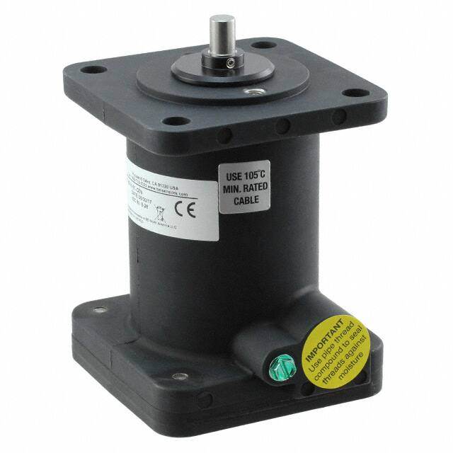
The H38 is an explosion proof version of the field-proven H25 encoder
series. The H38 is UL certified for NEMA Class 4X and 6 (outdoor
nonhazardous locations) and Class 4X and 13 (indoor non-hazardous
locations). It is available with single and triple certifications for use in
hazardous locations and includes a standard shaft seal, double bearing
seals, and a cast aluminum housing with hard anodized and dichromate
sealed finish. The H38 is suitable for use in petroleum service industries,
solvent refining operations, spray painting applications, and explosive
dust environments.
SPECIFICATIONS
Mechanical
Shaft Diameter
3/8” nominal
Shaft Loading
Up to 40 pounds axial and 20 pounds radial applied 1/4” from housing
Shaft Runout
0.0005 T.I.R
Starting Torque at 25°C
Bearings
Shaft Material
Enclosure
Bearing Life
Maximum RPM
Moment of Inertia
Weight
4.0 in-oz (max)
Class ABEC 7 standard
303 stainless steel
Die cast aluminum, hard anodized with dichromate sealed finish. Shaft seals and sealed
bearings are standard to achieve environmental ratings.
2 X 10⁸ revs (1300 hrs at 2500 RPM) at rated load; 1 X 10¹⁰ revs (67,000 hrs at 2500 RPM) at
10% of rated load
10,000 RPM (see frequency response, below)
4.1 X 10⁻⁴ oz-in-sec2 UL & MSHA/ 1.7 X 10⁻³ oz-in-sec2 CEN
64 oz typical (approx 4 lbs)
Page 1
Copyright © 2018 Sensata Technologies, Inc.
www.sensata.com
�SPECIFICATIONS (CONTINUED)
Electrical
Code
Incremental
Output Format
2 channels in quadrature, 1/2 cycle index gated with negative B channel
Cycles per Shaft Turn
1 to 72,000 (see table 2, page 5). For resolutions above 3,600 see Note 7.
Supply Voltage
Current Requirements
5 to 28 VDC
100 mA typical +output load, 250 mA (max)
Voltage/Output
(see note 3)
15V/V: Line Driver, 5–15 VDC in, Vout = Vin
28V/V: Line Driver, 5–28 VDC in, Vout = Vin
28V/5: Line Driver, 5–28 VDC in, Vout = 5 VDC
28V/OC: Open Collector, 5–28 VDC in, OCout
Protection Level
Reverse, overvoltage and output short circuit (see note 3)
Frequency Response
100 KHz Typical, Higher frequency response available, see note 5
Output Terminations
see Table 1, page 5
Termination Type
Note
Compression type, UL recognized. Accepts AWG 14 to 22, stranded wire, strip 1/4”
Consult factory for other electrical options
Environmental
Enclosure Rating
Temperature
Shock
NEMA 4 X & 6 (IP66), outdoor Non-Hazardous locations, NEMA 4 X & 13 (IP66), indoor NonHazardous locations
Standard operating all models, 0° to +70°C; Storage all models, -50° to +90°C; Extended temp
testing avail.: for UL, -40° to +80°C; for CEN, -50° to +90°C
50 g’s at 11 msec
Vibration
5 to 2000 Hz @ 20 g’s
Humidity
100% RH
Hazardous Area Rating
UL listed for use in hazardous locations. Class I, Group D, or Class I, Groups C & D, and Class II,
Groups E, F & G. NEMA Enclosure 7.
Notes & Tables: All notes and tables referred to in the text can be found on pages 4 and 5.
Page 2
Copyright © 2018 Sensata Technologies, Inc.
www.sensata.com
�DIMENSIONS
Dimensions in inches
Page 3
Copyright © 2018 Sensata Technologies, Inc.
www.sensata.com
�NOTES
1. Non-standard index widths and multiple indices are available by special order. Consult factory.
2. Complementary outputs are recommended for use with line driver type (source/sink) outputs. When used with differential receivers, this combination
provides a high degree of noise immunity.
3. Output IC’s: Output IC’s are available as either Line Driver (LD) or NPN Open Collector (OC) types. Open Collectors require pull-up resistors, resulting
in higher output source impedance (sink impedance is similar to that of line drivers). In general, use of a Line Driver style output is recommended.
Line Drivers source or sink current and their lower impedance means better noise immunity and faster switching times. Warning: Do not connect any
line driver outputs directly to circuit common/OV. Those may damage the driver. Unused outputs should be isolated and left floating. Our applications
specialists would be pleased to discuss your system requirements and the compatibility of your receiving electronics with Line Driver type outputs.
28V/V: Multi-voltage Line Driver (7272*): 100 mA source/sink. Input voltage 5 to 28 VDC +/- 5% standard (Note: Vout = Vin). This driver is TTL
compatible when used with 5 volt supply. Supply lines are protected against overvoltage to 60 volts and reverse voltage. Outputs are short circuit
protected for one minute. Supply current is 120 mA typical (plus load current). This is the recommended replacement for 3904R and 7406R open
collector outputs with internal pullup resistors. It is also a direct replacement for any 4469, 88C30, 8830 or 26LS31 line driver 28V/5: Multi-voltage
Line Driver (7272*): 100 mA source/sink. Input voltage 5 to 28 VDC +/- 5% standard, internally regulated with 5V (TTL compatible) logic out. Supply
lines are protected against overvoltage to 60 volts and reverse voltage. Outputs are short circuit protected for one minute. Supply current is 90 mA
typical (plus load current). 15V/V: Multi-voltage Line Driver (4469*): 100 mA source/sink. Input voltage 5 to 15 VDC +/- 5% standard (Note: Vout =
Vin). TTL compatible when used with 5 volt. Supply lines are protected against overvoltage to 60 volts and reverse voltage. Outputs are short circuit
protected for one minute. Supply current is 90 mA typical (plus load current). This is a direct replacement for the 4469 Line Driver. 28V/OC: NPN
Open Collector (3904*, 7273*). Current sink of 80 mA max. Current sourced by external pull- up resistor. Output can be pulled up to voltage other than
supply voltage (30 V max). Input voltage 5 to 28 VDC +/- 5% standard. Supply current is 120 mA typical. This replaces prior IC’s with designations
of 3904, 7406, 3302, 681 and 689. 5V/OCR, 15V/OCR, 24V/OCR: Open Collector (3904R*, 7406R*, 7273R*): Current sink of 70 mA max. Includes
internal pull-ups sized at approximately 100 ohms/ volt. Max current source is 10 mA. Supply current is 100 mA typical, 120 mA with internal pull-ups.
The 5V/OCR, 15V/OCR and 24V/OCR are often replaced by the 28V/V in system upgrades.
4. Special –S at the end of the model number is used to define a variety of non-standard features such as special shaft lengths, voltage options, or
special testing. Please consult the factory to discuss your special requirements.
5. Higher frequency response may be available. Please consult with the factory.
6. Extended temperature ratings are available. Consult with factory for more specific information.
7. For interpolation options, contact factory. See Doc. 01059-000 supplied with encoders for Important Installation and Usage notes summarized here.
Encoder Installation
1. Environment: Hazardous Locations — UL Complies with UL and cUL requirements; CEN Shall comply with UL requirements plus CENELAC/ATEX
plus IECEx standards
2. WARNING: Open all circuits prior to connecting this product to power and controller.
3. The installation must comply with NEC Class 2 circuits or with the regulations of the country of use.
4. AWG 14 - 22 stranded wire stripped to .25” [6.3mm} is recommended.
5. Use agency approved 105° C minimum rated cable/conductors housed within an approved rigid conduit.
6. Conduit runs must have a sealing fitting certified to 60079-0 Ex d IIB immediately at the entrance to the device.
7. Tightly close terminal block access cover prior to applying power.
8. For maximum bearing life, a flexible coupling is recommended between encoder shaft and driving shaft.
9. Thread sealant compound should be used for 1/2-14 fitting or cable gland to prevent ingress of contamination.
During Use
1. Keep terminal block access tightly secured during use.
2. DO NOT loosen two 5/16” set screws at opposite face.
Maintenance and Service
1. There are no user serviceable parts inside. Encoder must be returned to factory for service.
2. WARNING: Open all circuits to this product prior to opening access cover to disconnect wires.
Page 4
Copyright © 2018 Sensata Technologies, Inc.
www.sensata.com
�TABLES
Table 1 - Output Terminations
Terminal Pin No.
Ouput
1
CASE GROUND
2
0V
3
+V
4
A
5
B
6
Z
7
A
8
B
9
Z
10
SPARE
11
SPARE
Table 2 –Disc Resolutions for Incremental Encoder
Model H38
1, 2, 3, 5, 6, 7, 8, 10, 13, 16, 20, 24, 25, 26, 30, 32, 33, 34, 36, 37, 40, 45, 48, 50, 51, 56*, 60, 64, 66, 72, 75, 80, 86, 88, 90, 100, 102, 120, 122,125,
127, 128, 132, 144, 148, 150, 158, 160, 175, 176, 180, 187, 192, 200, 202, 204*, 217, 220, 240, 250, 254, 255, 256, 264*, 274, 280, 283, 288, 292,
300, 312, 320, 321, 325, 360, 366, 372, 375, 377, 380, 381, 384, 385, 393, 400, 430, 432, 450, 462, 480, 490, 500, 502, 508, 512, 522, 530, 550,
560*, 576, 598, 600, 604, 625, 628, 635, 638, 640, 660, 672, 676, 680, 687, 690, 700, 720, 725, 735, 740, 744, 748, 750, 762, 768, 780, 785, 800,
812, 825, 850, 864, 878, 888, 900, 912, 914, 938, 942, 955, 960, 1000, 1016, 1024, 1030, 1035, 1036, 1040, 1054, 1056, 1074, 1076, 1080,1088,
1100, 1101, 1125, 1136, 1200, 1237, 1250, 1257, 1270, 1280, 1300, 1314, 1332, 1333, 1390, 1400, 1414, 1427, 1440, 1484, 1500, 1562, 1570, 1596,
1600, 1650, 1666, 1718, 1745, 1774, 1800, 1840*, 1850, 1855, 1875, 1894, 1920, 1952, 1968, 1979, 1995, 2000, 2048, 2080, 2094, 2100, 2160,
2164, 2199, 2200, 2250, 2356, 2400, 2485, 2500, 2514, 2519, 2540, 3000, 3125, 3600, 4000, 4096, 5000
*AB or ABC output only.
NOTE: Resolutions up to 72,000 are available. See Note 7.
Page 5
Copyright © 2018 Sensata Technologies, Inc.
www.sensata.com
�Example : H38D-2000-ABZC-28V/V-SC-CEN
ORDERING OPTIONS
Type
H38
D
2000
ABZ
C
28V/V
SC
CEN
H = Heavy Duty;
38 = 3.75” Square
Housing Configuration
D = Standard (see dimensions, page 3)
Cycles Per Turn
Enter Cycles, See Table 2
No. of Channels
A = Single Channel
AB = Dual Quad. Ch.
ABZ = Dual with Index
AZ = Single with Index
See note 1
Complements
C = Complementary Outputs,
Blank = None
See note 2
Voltage/Output
15V/V = 5–15 Vin/out
28V/V = 5–28Vin/out
28V/5 = 5–28Vin/5Vout
28V/OC = 5–28Vin/OCout
See note 3
Output Termination
SC = Side Conduit, 1/2–14 NPSF (dryseal) straight pipe threads Accepts both NPS and NPT Type fittings
Certification
UL = Class I Group D Environments
CEN = UL, Cenelec, IECEx
MSHA = Mine Safety and Health Administration Certified
Special Features
S = Special features specified on purchase order (consult factory)
See note 4
Page 6
Copyright © 2018 Sensata Technologies, Inc.
www.sensata.com
�AGENCY APPROVALS & CERTIFICATIONS
EN 61000-6-4 and EN 61000-6-2
Ex d IIB T4 Gb
IECEx UL 14.0006X
II 2 G Ex d IIB T4 Gb
Class I, Group C & D;
Class II Group E,F & G;
The Mine Safety and Health Administration (MSHA) is an organization
that operates in the United States and enforces compliance with safety
and health standards in the Nation’s mines. Consult factory for MSHA
rated product.
Page 7
Sensata Technologies, Inc. (“Sensata”) data sheets are solely intended to assist designers (“Buyers”) who are developing systems that
incorporate Sensata products (also referred to herein as “components”). Buyer understands and agrees that Buyer remains responsible
for using its independent analysis, evaluation and judgment in designing Buyer’s systems and products. Sensata data sheets have
been created using standard laboratory conditions and engineering practices. Sensata has not conducted any testing other than that
specifically described in the published documentation for a particular data sheet. Sensata may make corrections, enhancements,
improvements and other changes to its data sheets or components without notice.
Buyers are authorized to use Sensata data sheets with the Sensata component(s) identified in each particular data sheet. HOWEVER, NO
OTHER LICENSE, EXPRESS OR IMPLIED, BY ESTOPPEL OR OTHERWISE TO ANY OTHER SENSATA INTELLECTUAL PROPERTY RIGHT, AND
NO LICENSE TO ANY THIRD PARTY TECHNOLOGY OR INTELLECTUAL PROPERTY RIGHT, IS GRANTED HEREIN. SENSATA DATA SHEETS
ARE PROVIDED “AS IS”. SENSATA MAKES NO WARRANTIES OR REPRESENTATIONS WITH REGARD TO THE DATA SHEETS OR USE
OF THE DATA SHEETS, EXPRESS, IMPLIED OR STATUTORY, INCLUDING ACCURACY OR COMPLETENESS. SENSATA DISCLAIMS
ANY WARRANTY OF TITLE AND ANY IMPLIED WARRANTIES OF MERCHANTABILITY, FITNESS FOR A PARTICULAR PURPOSE, QUIET
ENJOYMENT, QUIET POSSESSION, AND NON-INFRINGEMENT OF ANY THIRD PARTY INTELLECTUAL PROPERTY RIGHTS WITH REGARD
TO SENSATA DATA SHEETS OR USE THEREOF.
All products are sold subject to Sensata’s terms and conditions of sale supplied at www.sensata.com SENSATA ASSUMES NO LIABILITY
FOR APPLICATIONS ASSISTANCE OR THE DESIGN OF BUYERS’ PRODUCTS. BUYER ACKNOWLEDGES AND AGREES THAT IT IS SOLELY
RESPONSIBLE FOR COMPLIANCE WITH ALL LEGAL, REGULATORY AND SAFETY-RELATED REQUIREMENTS CONCERNING ITS PRODUCTS,
AND ANY USE OF SENSATA COMPONENTS IN ITS APPLICATIONS, NOTWITHSTANDING ANY APPLICATIONS-RELATED INFORMATION
OR SUPPORT THAT MAY BE PROVIDED BY SENSATA.
Mailing Address: Sensata Technologies, Inc., 529 Pleasant Street, Attleboro, MA 02703, USA.
Copyright © 2018 Sensata Technologies, Inc.
02051-001 Rev: 01/09/19
CONTACT US
Americas
+1 (800) 350 2727 – Option 1
sales.beisensors@sensata.com
Europe, Middle East & Africa
+33 (3) 88 20 8080
position-info.eu@sensata.com
Asia Pacific
sales.isasia@list.sensata.com
China +86 (21) 2306 1500
Japan +81 (45) 277 7117
Korea +82 (31) 601 2004
India +91 (80) 67920890
Rest of Asia +886 (2) 27602006
ext 2808
www.sensata.com
�


 工商网监
湘ICP备2023018690号
工商网监
湘ICP备2023018690号