| L25
INCREMENTAL OPTICAL ENCODER
Introduction
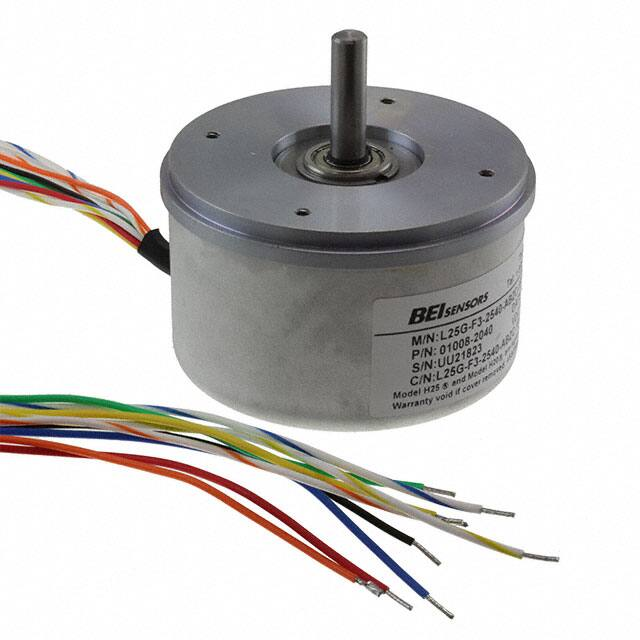
The L25 is a lighter duty version of BEI’s H25 optical encoder
Incorporating the same high quality optics and electronics as the H25,
the L25 also offers low starting torque. Other features include ABEC
5 bearings, EMI shielding, a 1/4” diameter stainless steel shaft and
a drawn aluminum cover. Typical applications include use with light
machine tools, test and laboratory instrumentation, the biomedical
industry and flow metering.
MECHANICAL SPECIFICATIONS
Shaft Diameter
1/4” nominal
Flat On Shaft
0.80 long x 0.03 deep
Shaft Loading
up to 5 lbs. axial and 8 lbs. radial
Shaft Runout
.0005 T.I.R. maximum
Starting Torque at 25°C
Bearings
Shaft Material
Bearing Housing
Cover
Bearing Life
Maximum RPM
Moment of Inertia
Weight
0.07 in-oz typical, 0.12 in-oz maximum without sealed
bearings; 0.50 in-oz typical, 1.0 in-oz maximum with sealed bearings
Class ABEC 5
416 stainless steel
Die cast aluminum with iridite finish
Drawn aluminum, 0.060” wall, protective finish standard. Die cast aluminum
with protective finish for EM, SM, ECS and SCS terminations
1 X 10⁹ revs (6,700 hrs at 2500 RPM)
10,000 RPM
4.1 x 10 -4 oz-in-sec2
13 oz. typical
Page 1
Copyright © 2018 Sensata Technologies, Inc.
www.sensata.com
�ELECTRICAL SPECIFICATIONS
Code
Incremental
Cycles per Shaft Turn
1 to 28,800
(see note 5)
15V/V: Line Driver, 5–15 VDC in, Vout = Vin
28V/V: Line Driver, 5–28 VDC in, Vout = Vin
28V/5V: Line Driver, 5–28 VDC in, Vout = 5 VDC
28V/OC: Open collector, 5–28 VDC in, OCout
Voltage/ Output
Current Requirements
TTL: 175 mA maximum 125 mA typical
2 channels in quadrature = 27º electrical typical.
Optional index is typically gated 1/2 cycle wide (see figure 1)
Output Format
Protection Level
Reverse, overvoltage and output short circuit (4469, 7272 only)
Frequency Response
100 KHz (see note 7), up to 800 KHz with interpolation option
Output Terminations
(See Table 1)
ENVIRONMENTAL SPECIFICATIONS
Enclosure Rating
Temperature
Shock
NEMA 2 (IP43)
Operating, 0º to 70º C; extended temperature
testing available (see note 8); storage; -25º to 90º C
50 g’s for 11 msec duration
Vibration
5 to 2000 Hz @ 20 G’s
Humidity
98% RH without condensation
DIMENSIONS
L25G - M16 or M18
Optional Face Mounts
Page 2
Copyright © 2018 Sensata Technologies, Inc.
www.sensata.com
�TABLES
Table 1–Incremental Output Terminations
The connector style will determine pinouts. For example, an encoder with ABC channels and an M18 connector uses the table to the right.
M14 CONNECTOR
PIN
E
D
C
B
F
A
M16 CONNECTOR
PIN
A
B
C
D
E
F
G
WIRE COLOR
DA 15P CONNECTOR
YEL
BLUE
ORN
W-YEL
W-BLU
W-OM
RED
BLK
GRN
WHITE
13
14
15
10
11
12
6
1
9
CHANNELS DESIGNATED IN MODEL NO.
ABZ
ABC
A
A
B
B
Z
A
+V (SUPPLY VOLTAGE)
B
0 V (CIRCUIT COMMON)
CASE GROUND (CG) (except H20)
M18 Connector
PIN
Channel
A
A
B
B
C
Z
D
+V
E
F
0V
G
CG
H
A
I
B
J
Z
CHANNELS DESIGNATED IN MODEL NO.
ABZ
ABC
ABZC
A
A
A
B
B
B
Z
Z
A
A
B
B
Z
+V (SUPPLY VOLTAGE)
0 V (CIRCUIT COMMON)
CASE GROUND (CG) (except H20)
SHIELD DRAIN (Shielded Cable Only)
M12 Connector
PIN
Channel
A
A
B
B
C
Z
D
+V
E
F
0V
G
CG
H
A
J
Z
K
Z
Table 2–Disc Resolutions for Incremental Encoder Model L25
1, 2, 3, 5, 6, 7, 8, 10, 13, 16, 20, 24, 25, 26, 30, 32, 33, 34, 36, 37, 40, 45, 48, 50, 51, 56*, 60, 64, 66, 72, 75,
80, 86, 88, 90, 100, 102, 120, 122,125, 127, 128, 132, 144, 148, 150, 158, 160, 175, 176, 180, 187, 192, 200,
202, 204*, 217, 220, 240, 250, 254, 255, 256, 264*, 274, 280, 283, 288, 292, 300, 312, 320, 321, 325, 360,
366, 372, 375, 377, 380, 381, 384, 385, 393, 400, 430, 432, 450, 462, 480, 490, 500, 502, 508, 512, 522,
530, 550, 560*, 576, 598, 600, 604, 625, 628, 635, 638, 640, 660, 672, 676, 680, 687, 690, 700, 720, 725,
735, 740, 744, 748, 750, 762, 768, 780, 785, 800, 812, 825, 850, 864, 878, 888, 900, 912, 914, 938, 942,
955, 960, 1000, 1016, 1024, 1030, 1035, 1036, 1040, 1054, 1056, 1074, 1076, 1080,1088, 1100, 1101, 1125,
1136, 1200, 1237, 1250, 1257, 1270, 1280, 1300, 1314, 1332, 1333, 1390, 1400, 1414, 1427, 1440, 1484,
1500, 1562, 1570, 1596, 1600, 1650, 1666, 1718, 1745, 1774, 1800, 1840*, 1850, 1855, 1875, 1894, 1920,
1952, 1968, 1979, 1995, 2000, 2048, 2080, 2094, 2100, 2160, 2164, 2199, 2200, 2250, 2356, 2400, 2485,
2500, 2514, 2519, 2540, 3000, 3125, 3600, 4000, 4096, 5000
Output Waveform
Figure 1
1 CYCL E
90 Deg.
HI
LO
A
B
Z
A
B
Z
CCW Rotation Viewing Fac
e
Copyright © 2018 Sensata Technologies, Inc.
Page 3
www.sensata.com
�Example : L25G-F3-SB-2000-ABZC-28V/V-SC18
ORDERING OPTIONS
Use this diagram, working from left to right to construct your model number
L25
G
-
-
-
-
-
-
-
Type
L = Heavy Duty
25 = 2.500” Dia.
Housing Config. Letter
G = 2.62 Dia. Servo Mount
See dimensions
Optional Face Mounts
F1, F2, F3, or F4
Blank = None
Shaft Seal Config.
SB = Seal Integral with Bearing
Blank = Shielded Bearing
Cycles per Turn
(Enter Cycles) See table 2
No. of Channels
A = Single Channel
AB = Dual Quad. Ch.
ABZ = Dual with Index
AZ = Single with Index
See note 3
Complements
C = Complementary Outputs
Blank = None
See note 4
Voltage/Output
15V/V = 5-15 Vin/out
28V/V = 5-28Vin/out
28V/5 = 5-28Vin/5Vout
M18 = 5-28Vin/OCout
See note 5
Output Termination Location
E = End
S = Side
Output Termination
M16 = MS3102R16S-1P
D15 = DA15P
C = Pigtail Cable
CS = Cable with Seal Cable length specified in inches
(i.e. C18 = Pigtail 18” long)
See table 1 & note 9
Special Features
S = Special features specified on purchase order (consult factory)
See table 6
Page 4
Copyright © 2018 Sensata Technologies, Inc.
www.sensata.com
�NOTES
1. Mounting is usually done either using the D-style square flange mount, E- or G-style servo mounts, or one of the standard face mounts, F1
for example. Consult factory for additional face mount options.
2.The shaft seal is recommended in virtually all installations. The most common exceptions are applications requiring a very low starting
torque or those requiring operation at both high temperature and high speed.
3. Non-standard index widths and multiple indices are available by special order. Consult factory.
4. Complementary outputs are recommended for use with line driver type (source/ sink) outputs. When used with differential receivers, this
combination provides a high degree of noise immunity.
5. Output IC’s: Output IC’s are available as either Line Driver (LD) or NPN Open Collector (OC) types. Open Collectors require pull-up resistors,
resulting in higher output source impedance (sink impedance is similar to that of line drivers). In general, use of a Line Driver style output is
recommended. Line Drivers source or sink current and their lower impedance mean better noise immunity and faster switching times.
Warning: Do not connect any line driver outputs directly to circuit common/OV, which may damage the driver. Unused outputs should be
isolated and left floating. Our applications specialists would be pleased to discuss your system requirements and the compatibility of your
receiving electronics with Line Driver type outputs. 28V/V: Multi-voltage Line Driver (7272*): 100 mA source/sink. Input voltage 5 to 28 VDC
+/- 5% standard (Note: Vout = Vin). This driver is TTL compatible when used with 5 volt supply. Supply lines are protected against overvoltage
to 60 volts and reverse voltage. Outputs are short circuit protected for one minute. Supply current is 120 mA typical (plus load current). This
is the recommended replacement for 3904R and 7406R open collector outputs with internal pullup resistors. It is also a direct replacement
for any 4469, 88C30, 8830 or 26LS31 line driver 28V/5: Multi-voltage Line Driver (7272*): 100 mA source/sink. Input voltage 5 to 28 VDC +/5% standard, internally regulated with 5V (TTL compatible) logic out. Supply lines are protected against overvoltage to 60 volts and reverse
voltage. Outputs are short circuit protected for one minute. Supply current is 90 mA typical (plus load current). Note: Limit encoder load to
2.5W max at ambient. Example at 12 VDC: 2.5W/(+12VDC minus +5VDC) = 357 mA total allowed current. Consult factory for your specific
requirements. 15V/V: Multi-voltage Line Driver (4469*): 100 mA source/sink. Input voltage 5 to 15 VDC +/- 5% standard (Note: Vout = Vin).
TTL compatible when used with 5 volt supply. Supply lines are protected against overvoltage to 60 volts and reverse voltage. Outputs are
short circuit protected for one minute. Supply current is 90 mA typical (plus load current). This is a direct replacement for the 4469 Line Driver.
28V/OC: NPN Open Collector (3904*, 7273*). Current sink of 80 mA max. Current sourced by external pull- up resistor. Output can be pulled
up to voltage other than supply voltage (30 V max). Input voltage 5 to 28 VDC +/- 5% standard. Supply current is 120 mA typical. This replaces
prior IC’s with designations of 3904, 7406, 3302, 681 and 689. 5V/OCR, 15V/OCR, 24V/ OCR: Open Collector (3904R*, 7406R*, 7273R*):
Current sink of 70 mA max. Includes internal pull-ups sized at approximately 100 ohms/volt. Max current source is 10 mA. Supply current is
100 mA typical, 120 mA with internal pullups. The 5V/OCR, 15V/OCR and 24V/OCR are often replaced by the 28V/V in system upgrades.
3904, 3904R, 4469, 5V/V, 5V/OC, 5V/OCR, 9V/OC: Intrinsically safe line driver and open collector outputs. These drivers are specific to
intrinsically safe encoders, and are installed per the appropriate control drawings listed in Table 2.on this page.
6. Special –S at the end of the model number is used to define a variety of non-standard features such as special shaft lengths, voltage
options, or special testing. Please consult the factory to discuss your special requirements.
7. Higher frequency response may be available. Please consult with the factory.
8. Extended temperature ratings are available in the following ranges: -40 to 70°C, -40 to 85°C, –20 to 105°C and –40 to 105°C depending on
the particular model. Some models can operate down to -55°C. Extended temperature ranges can affect other performance factors. Consult
with factory for more specific information.
9. Mating straight plug receptacles may be ordered from the factory:
For M12 use MS3116F12-10S, For M14 use MS3106F14S-6S
For M14/19 use MS3116J14-19S, For M16 use MS3106F16S-1S
For M18 use MS3106F18-1S, For M20 use MS3106F20-29S
Page 5
Made In France
Sensata Technologies, Inc. (“Sensata”) data sheets are solely intended to assist designers (“Buyers”) who are developing systems that
incorporate Sensata products (also referred to herein as “components”). Buyer understands and agrees that Buyer remains responsible
for using its independent analysis, evaluation and judgment in designing Buyer’s systems and products. Sensata data sheets have
been created using standard laboratory conditions and engineering practices. Sensata has not conducted any testing other than that
specifically described in the published documentation for a particular data sheet. Sensata may make corrections, enhancements,
improvements and other changes to its data sheets or components without notice.
Buyers are authorized to use Sensata data sheets with the Sensata component(s) identified in each particular data sheet. HOWEVER, NO
OTHER LICENSE, EXPRESS OR IMPLIED, BY ESTOPPEL OR OTHERWISE TO ANY OTHER SENSATA INTELLECTUAL PROPERTY RIGHT, AND
NO LICENSE TO ANY THIRD PARTY TECHNOLOGY OR INTELLECTUAL PROPERTY RIGHT, IS GRANTED HEREIN. SENSATA DATA SHEETS
ARE PROVIDED “AS IS”. SENSATA MAKES NO WARRANTIES OR REPRESENTATIONS WITH REGARD TO THE DATA SHEETS OR USE
OF THE DATA SHEETS, EXPRESS, IMPLIED OR STATUTORY, INCLUDING ACCURACY OR COMPLETENESS. SENSATA DISCLAIMS
ANY WARRANTY OF TITLE AND ANY IMPLIED WARRANTIES OF MERCHANTABILITY, FITNESS FOR A PARTICULAR PURPOSE, QUIET
ENJOYMENT, QUIET POSSESSION, AND NON-INFRINGEMENT OF ANY THIRD PARTY INTELLECTUAL PROPERTY RIGHTS WITH REGARD
TO SENSATA DATA SHEETS OR USE THEREOF.
All products are sold subject to Sensata’s terms and conditions of sale supplied at www.sensata.com SENSATA ASSUMES NO LIABILITY
FOR APPLICATIONS ASSISTANCE OR THE DESIGN OF BUYERS’ PRODUCTS. BUYER ACKNOWLEDGES AND AGREES THAT IT IS SOLELY
RESPONSIBLE FOR COMPLIANCE WITH ALL LEGAL, REGULATORY AND SAFETY-RELATED REQUIREMENTS CONCERNING ITS PRODUCTS,
AND ANY USE OF SENSATA COMPONENTS IN ITS APPLICATIONS, NOTWITHSTANDING ANY APPLICATIONS-RELATED INFORMATION
OR SUPPORT THAT MAY BE PROVIDED BY SENSATA.
Mailing Address: Sensata Technologies, Inc., 529 Pleasant Street, Attleboro, MA 02703, USA.
Copyright © 2018 Sensata Technologies, Inc.
02004-001 Rev: 05/03/2018
CONTACT US
Americas
+1 (800) 350 2727
sales.beisensors@sensata.com
Europe, Middle East & Africa
+33 (3) 88 20 8080
position-info.eu@sensata.com
Asia Pacific
sales.isasia@list.sensata.com
China +86 (21) 2306 1500
Japan +81 (45) 277 7117
Korea +82 (31) 601 2004
India +91 (80) 67920890
Rest of Asia +886 (2) 27602006
ext 2808
www.sensata.com
�