L-GAGE® Q50 Series with Analog Output
Datasheet
LED-Based Linear Displacement Sensor with Analog Output and TEACH-Method Configuration
•
•
•
•
•
•
•
•
•
•
•
•
Fast, easy-to-use integrated push button TEACH-method configuration;
no potentiometer adjustments
Selectable output response speeds: 4 milliseconds or 64 milliseconds
Teach a sensing window size and position, or set-point threshold
centered within a 100 mm window
Two sensing ranges, depending on model: 100 mm to 300 mm (visible
red beam models) and 100 mm to 400 mm (infrared beam models)
Sensor linearity is better than 3 mm
Banner's patented scalable analog output1 automatically distributes the
output signal over the width of configured sensing window
Analog output slope is either positive or negative, depending upon
which window limit is configured first
Two bicolor Status LEDs
Choose 2 m (6.6 ft) or 9 m (29.5 ft) unterminated cable, or swivel 5-pin
Euro-style quick-disconnect connector
Rugged construction withstands demanding sensing environments;
rated IEC IP67, NEMA 6
Select models with either visible red or infrared beam
Select models with either a 0 V to 10 V or 4 mA to 20 mA output
WARNING:
• Do not use this device for personnel protection
• Using this device for personnel protection could result in serious injury or death.
• This device does not include the self-checking redundant circuitry necessary to allow its use in
personnel safety applications. A device failure or malfunction can cause either an energized (on) or deenergized (off) output condition.
Models
Model Number
Sensing Range
Cable2
100 mm to 300 mm (3.9
in to 11.8 in)
5-pin Euro-style quick-disconnect
Q50BVI
Q50BVIQ
Q50BVU
Q50BUQ
5-wire, 2 m (6.5 in) cable
100 mm to 400 mm (3.9
in to 15.7 in)
5-pin Euro-style quick-disconnect
5-wire, 2 m (6.5 in) cable
5-pin Euro-style quick-disconnect
Output
4 mA to 20 mA
Visible Red LED
5-wire, 2 m (6.5 in) cable
5-pin Euro-style quick-disconnect
Q50BI
Q50BU
Beam
5-wire, 2 m (6.5 in) cable
Q50BVUQ
Q50BIQ
Supply Voltage
0 V to 10 V
15 V DC to 30 V DC
4 mA to 20 mA
Infrared LED
0 V to 10 V
1 U.S. patent #6,122,039
2 To order the 9 m (30 ft) PVC cable model, add the suffix "W/30" to the cabled model number. Models with a quick disconnect require a mating cordset.
Original Document
64323 Rev B
11 February 2020
64323
�L-GAGE® Q50 Series with Analog Output
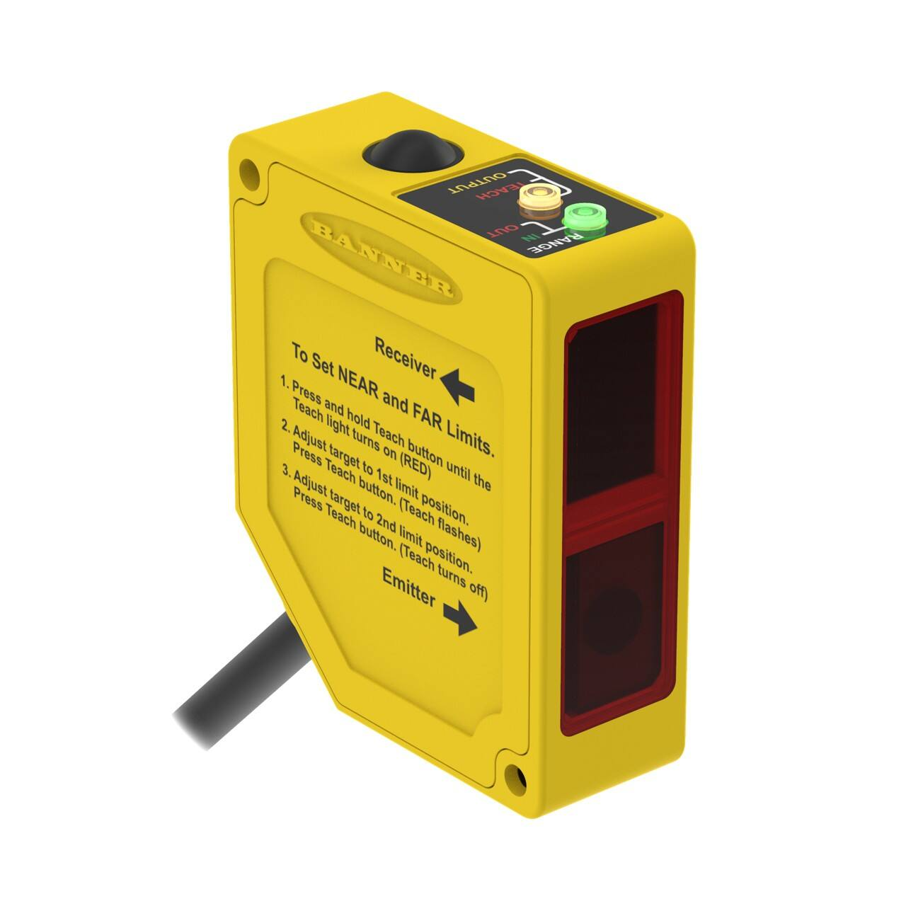
Overview
Teach/Output
Indicator LED
(yellow or red)
Programming
Push Button
Range
Indicator LED
(red or green)
The Q50 is an easy-to-use triangulation sensor which provides a
sophisticated, yet cost-effective solution for demanding
measurement applications. Q50 series sensors feature compact,
all-in-one design and require no separate controller.
Near and far sensing window limits are set quickly using simple
push-button or remote signal TEACH-method configuration. The
analog output has the option of being set with a sensing
distance centered within a 100 mm window. The sensor features
Banner's patented digital signal processing algorithm3, which
automatically distributes the 0 V DC to 10 V DC (or 4 mA to 20
mA) output signal over the width of the configured window.
QD fitting rotates for wiring in any direction
Figure 1. L-GAGE Q50 sensor features
Indicator Status Conditions
Indicator
Status
Range LED (green/red)
Green – Target is within sensing range (either 100 mm to 300 mm for visiblebeam models, or 100 mm to 400 mm for infrared beam models)
Red – Target is outside sensing range
OFF – Sensor Power OFF
Teach/Output LED (amber/red)
Amber – Target is within taught window limits
OFF – Target is outside taught window limits
Red – Sensor is in TEACH configuration
3
2
U.S. patent #6,122,039
www.bannerengineering.com - Tel: + 1 888 373 6767
P/N 64323 Rev B
�L-GAGE® Q50 Series with Analog Output
Optical Triangulation
PSD Receiver
Element
R
Signal
Conditioning
Circuitry
Lenses
Near
Limit
Far
Limit
Target Movement
Microprocessor
Output
Circuitry
Emitter
Circuitry
E
Laser
Emitter
The function of the Q50 sensor is based on optical
triangulation. The emitter circuitry and optics create a
light source which is directed toward a target. The
light source bounces off the target, scattering some
of its light through another lens to the sensor's
position-sensitive device (PSD) receiver element. The
target's distance from the receiver determines the
light's angle to the receiver element. This angle
determines where the returned light will fall along the
PSD receiver element.
The position of the light on the PSD receiver element
is processed through analog and digital electronics
and analyzed by the microprocessor, which
calculates the appropriate output value. The analog
output provides either a current or voltage output, or
a variable signal proportional to the target's position
within the user-configured analog window limits.
Programmed
Sensing Window
Figure 2. Using optical triangulation to determine sensing distance
Installation Notes
Some targets pose specific problems for sensing distances. Examples include those with a stepped plan facing the sensor, a
boundary line, or rounded targets. For such applications see Figure 3 on p. 3 and Figure 4 on p. 3 for suggested mounting
orientations.
Figure 3. Sensor orientations for typical targets: recommended
Figure 4. Sensor orientations for typical targets: not recommended
P/N 64323 Rev B
www.bannerengineering.com - Tel: + 1 888 373 6767
3
�L-GAGE® Q50 Series with Analog Output
Using the Q50 Analog Output Sensor
Response Speed
To control the response speed, connect the black wire as follows:
• Fast Speed (4 ms): Connect black wire to +5 V DC to 30 V DC
• Slow Speed (64 ms): Connect black wire to 0 V DC to +2 V DC (or open connection)
Window Limits
Window limits may be taught to the sensor either remotely (using the gray wire) or by using the sensor's Teach button.
The Q50 sensor operates in two modes: TEACH (or configuration mode) and Run mode.
Note: All LED indicators momentarily turn OFF when the sensor changes state between Run mode and TEACH
configuration.
Configuration Instructions
Push-Button Procedure
1. Press the Teach button until the Teach LED turns red (hold button in for about 2 seconds).
This indicates the sensor is waiting for the first window limit.
2. Configure the first limit.
a) Position the target for the first limit
The Range LED should be green, indicating a valid target.
b) Briefly press the Teach button.
The first limit is configured. The Teach LED flashes red at 2 Hz to acknowledge receiving the first window limit. It is now
waiting for the second limit.
3. Configure the second limit.
a) Position the target for the second limit.
The Range LED should be green, indicating a valid target.
b) Press the Teach button again.
The second limit is configured. The Teach LED will turn either amber or OFF as the sensor returns to RUN mode.
Remote Configuration
Configure the sensor remotely or disable/enable the push button using the gray wire. This is accomplished via the gray wire.
Disabling the push button prevents unauthorized or accidental changes to the configuration settings. Connect the gray wire of the
Q50 Gauging Sensor to +5 V DC to 30 V DC, with a remote configuration switch connected between them.
Note: The impedance of the remote teach input is 15 kΩ.
To configure, pulse the wire as illustrated in Figure 5 on p. 4. The duration of each button click or remote input pulse is defined
as T, where T is: 0.04 s < T < 0.8 s.
> 0.8 sec
T
Remote T each
Window Limits
T
Teach First
Window Limit
T
T
Teach Second
Window Limit
T
T
T
Push Button
Lockout
T
T
Push Button Lockout
0.04 sec < T < 0.8 sec
Figure 5. Timing for remote TEACH configuration
4
www.bannerengineering.com - Tel: + 1 888 373 6767
P/N 64323 Rev B
�L-GAGE® Q50 Series with Analog Output
Analog Output
The Q50 gauging sensor may be configured for either a positive or a negative output slope; see Figure 6 on p. 5. If the near limit
is taught first, the slope will be positive; if the far limit is taught first the slope will be negative. Banner's patented scalable analog
output automatically distributes the output signal over the width of the programmed sensing window. (Output is either 0 V to 10 V
or 4 mA to 20 mA, depending on the model.)
Current Models
20
10
Positive
Slope
Positive
Slope
Analog Output (mA)
Analog Voltage Output (V dc)
Voltage Models
0
4
Near
Window
Far
Window
Target Position
Figure 6. Analog voltage output as a function of target position (loss of signal – 0
V)
Near
Window
Target Position
Far
Window
Figure 7. Analog current output as a function of target position (loss of signal –
3.6 mA)
Teaching Analog Limits Using a Fixed 100 mm Window
For some analog applications, a sensing distance set point centered within a sensing window is required. The TEACH procedure is
simple: teaching the same limit twice causes the sensor to configure a window centered on the position taught. This window is 100
mm wide (taught position ±50 mm).
Wiring Diagrams
Quick disconnect wiring diagrams are functionally identical.
1
+
15-30V dc
–
3
2
5-30V dc
(fast response)
0-2V dc
(slow response)
4
5
Teach
Key
1 = Brown
2 = White
3 = Blue
4 = Black
5 = Gray
+ 5-30V dc
Bare
P/N 64323 Rev B
www.bannerengineering.com - Tel: + 1 888 373 6767
5
�L-GAGE® Q50 Series with Analog Output
Specifications
Sensing Range
Q50BV: 100 mm to 300 mm (3.9 in to 11.8 in)
Q50B: 100 mm to 400 mm (3.9 in to 15.7 in)
Remote and Speed Input Impedance
15 kΩ
Supply Voltage
15 V DC to 30 V DC (10% maximum ripple); 70 mA max. (exclusive of load)
Supply Protection Circuitry
Protected against reverse polarity and transient overvoltages
Remote Teach Input
To Teach: Connect gray wire to +5 V DC to 30 V DC
To Disable: Connect gray wire to 0 V DC to +2 V DC (or open connection)
Response Speed
Fast Speed: Connect black wire to +5 V DC to 30 V DC
Slow Speed: Connect black wire to 0 V DC to +2 V DC (or open connection)
Delay at Power-up
2 seconds
Sensing Beam
Q50BV: Visible red, 685 nm (typical); 20 mm dia. (max.) beam size
Q50B: Infrared, 880 nm (typical); 20 mm diameter (maximum) beam size
Output Configuration
Depending on model
4 mA to 20 mA current sourcing models: 1 kΩ max. load at 24 V dc. Max.
load = [(VCC-4.5)/0.02]Ω; loss of signal or target outside of sensor range: 3.6
mA
0 V to 10 V voltage sourcing models: 15 mA max.; loss of signal or target
outside of sensor range: 0 V
Minimum Taught Window
Target distance at 300 mm: 50 mm window
Target distance at 125 mm: 10 mm window
Ambient Light Immunity
很抱歉,暂时无法提供与“Q50BU”相匹配的价格&库存,您可以联系我们找货
免费人工找货