HI-5200
10 Base-T/100Base-TX Physical Layer Transceiver
with Extended Temperature Operation
August 2021
DS5200 Rev. F
HOLT INTEGRATED CIRCUITS
www.holtic.com
1
08/21
�HI-5200
Table of Contents
1. General Description............................................................................................. 7
2. Features.............................................................................................................. 7
3. Pin Configurations (Top)...................................................................................... 8
4. Block Diagram..................................................................................................... 9
5. Pin Descriptions................................................................................................ 10
5.1.
Strapping Options...................................................................................................... 13
6. Functional Description....................................................................................... 15
6.1.
100Base-TX Transmit................................................................................................ 15
6.2.
100Base-TX Receive................................................................................................. 15
6.3.
PLL Clock Synthesizer............................................................................................... 15
6.4.
Scrambler/De-Scrambler (100Base-TX only)............................................................ 16
6.5.
10Base-T Transmit..................................................................................................... 16
6.6.
10Base-T Receive..................................................................................................... 16
6.7.
SQE and Jabber Function (10Base-T only)............................................................... 16
6.8.
Auto-Negotiation........................................................................................................ 16
6.9.
MII Management (MIIM) Interface.............................................................................. 18
6.10. Interrupt (INTRP)....................................................................................................... 18
6.11. MII Data Interface...................................................................................................... 18
6.12. MII Signal Definition................................................................................................... 19
6.12.1.
Transmit Clock (TXC)............................................................................................. 19
6.12.2.
Transmit Enable (TXEN)........................................................................................ 19
6.12.3.
Transmit Data [3:0] (TXD[3:0])............................................................................... 19
6.12.4.
Receive Clock (RXC).............................................................................................. 20
6.12.5.
Receive Data Valid (RXDV).................................................................................... 20
6.12.6.
Receive Data [3:0] (RXD[3:0])................................................................................ 20
6.12.7.
Receive Error (RXER)............................................................................................ 20
6.12.8.
Carrier Sense (CRS).............................................................................................. 20
6.12.9.
Collision (COL)....................................................................................................... 20
6.13. Reduced MII (RMII) Data Interface............................................................................ 21
6.14. RMII Signal Definition................................................................................................ 21
6.14.1.
Reference Clock (REFCLK)................................................................................... 21
HOLT INTEGRATED CIRCUITS
2
�HI-5200
6.14.2.
Transmit Enable (TXEN)........................................................................................ 22
6.14.3.
Transmit Data [1:0] (TXD[1:0])............................................................................... 22
6.14.4.
Carrier Sense/Receive Data Valid (CRSDV).......................................................... 22
6.14.5.
Receive Data [1:0] (RXD[1:0])................................................................................ 22
6.14.6.
Receive Error (RXER)............................................................................................ 22
6.14.7.
Collision Detection.................................................................................................. 22
6.15. RMII Signal Diagram.................................................................................................. 22
6.16. HP Auto MDI/MDI-X................................................................................................... 24
6.16.1.
Straight Cable......................................................................................................... 24
6.16.2.
Crossover Cable..................................................................................................... 25
6.17. Reference Clock Connection Options........................................................................ 26
7. Power Management.......................................................................................... 27
7.1.
Power Saving Mode................................................................................................... 27
7.2.
Power-Down Mode.................................................................................................... 27
7.3.
Reference Circuit for Power and Ground Connections.............................................. 27
8. Register Map..................................................................................................... 29
9. Register Description.......................................................................................... 30
9.1.
Register 0h ‒ Basic Control....................................................................................... 30
9.2.
Register 1h ‒ Basic Status......................................................................................... 31
9.3.
Register 2h ‒ PHY Identifier 1................................................................................... 31
9.4.
Register 3h ‒ PHY Identifier 2................................................................................... 32
9.5.
Register 4h ‒ Auto-Negotiation Advertisement.......................................................... 32
9.6.
Register 5h ‒ Auto-Negotiation Link Partner Ability................................................... 33
9.7.
Register 6h ‒ Auto-Negotiation Expansion................................................................ 34
9.8.
Register 7h ‒ Auto-Negotiation Next Page................................................................ 34
9.9.
Register 8h ‒ Link Partner Next Page Ability............................................................. 35
9.10. Register 14h ‒ MII Control......................................................................................... 36
9.11. Register 15h ‒ RXER Counter................................................................................... 36
9.12. Register 1Bh ‒ Interrupt Control/Status..................................................................... 37
9.13. Register 1Eh ‒ PHY Control 1................................................................................... 38
9.14. Register 1Fh ‒ PHY Control 2................................................................................... 39
10. Absolute Maximum Ratings1........................................................................................................................................ 41
11. Operating Ratings3................................................................................................................................................................. 41
HOLT INTEGRATED CIRCUITS
3
�HI-5200
12. Electrical Characteristics1............................................................................................................................................... 42
12.1. Recommended Transformer Characteristics............................................................. 43
12.2. Typical Reference Crystal Characteristics................................................................. 43
13. Timing Diagrams............................................................................................... 44
13.1. MII Timing.................................................................................................................. 44
13.2. RMII Timing................................................................................................................ 49
13.3. Auto-Negotiation Timing............................................................................................. 50
13.4. MDC/MDIO Timing..................................................................................................... 51
13.5. Power-Up/Reset Timing............................................................................................. 52
14. Reset Circuits.................................................................................................... 53
15. Reference Circuits for LED Strapping Pins....................................................... 54
16. Recommended Single Port Magnetics.............................................................. 55
17. Ordering Information......................................................................................... 55
18. Revision History................................................................................................ 56
19. Package Dimensions......................................................................................... 57
HOLT INTEGRATED CIRCUITS
4
�HI-5200
List of Figures
Figure 1. HI-5200: 32-Pin Plastic 5mm x 5mm QFN...................................................................... 8
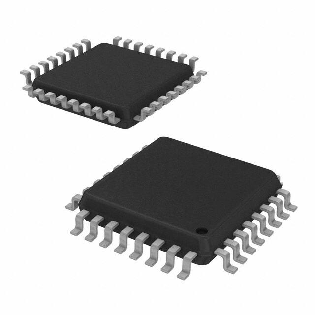
Figure 2. HI-5200: 32-Pin Plastic 9mm x 9mm TQFP.................................................................... 8
Figure 3. HI-5200 Block Diagram................................................................................................... 9
Figure 4. Auto Negotiation Flow Chart.......................................................................................... 17
Figure 5. HI-5200 RMII Interface.................................................................................................. 23
Figure 6. Typical Straight Cable Connection................................................................................ 24
Figure 7. Typical Crossover Cable Connection............................................................................ 25
Figure 8. a) 25MHz Crystal or b) 25MHz Oscillator Reference Clock for HI-5200 MII Mode....... 26
Figure 9. 50MHz Reference Clock for HI-5200 RMII Mode.......................................................... 26
Figure 10. HI-5200 Power and Ground Connections................................................................... 27
Figure 11. MII SQE Timing (10Base-T)......................................................................................... 44
Figure 12. MII Transmit Timing (10Base-T).................................................................................. 45
Figure 13. MII Receive Timing (10Base-T)................................................................................... 46
Figure 14. MII Transmit Timing (100Base-Tx).............................................................................. 47
Figure 15. MII Receive Timing (100Base-Tx)............................................................................... 48
Figure 16. RMII Transmit Timing.................................................................................................. 49
Figure 17. RMII Receive Timing................................................................................................... 49
Figure 18. Auto-Negotiation Fast Link Pulse (FLP) Timing........................................................... 50
Figure 19. MDC/MDIO Timing...................................................................................................... 51
Figure 20. Power-Up/Reset Timing.............................................................................................. 52
Figure 21. Recommended Reset Circuit...................................................................................... 53
Figure 22. Recommended Reset Circuit for interfacing with CPU/FPGA Reset Output............... 53
Figure 23. Reference Circuits for LED Strapping Pins................................................................. 54
HOLT INTEGRATED CIRCUITS
5
�HI-5200
List of Tables
Table 1. HI-5200 Pin Descriptions................................................................................................ 10
Table 2. HI-5200 Strapping Options............................................................................................. 13
Table 3. MII Management Frame Format..................................................................................... 18
Table 4. MII Signal Definition........................................................................................................ 19
Table 5. HI-5200 RMII Signal Definition........................................................................................ 21
Table 6. MDI/MDI-X Pin Description............................................................................................. 24
Table 7. HI-5200 Power and Ground Connections....................................................................... 28
Table 8. MII SQE Timing (10Base-T) Parameters........................................................................ 44
Table 9. MII Transmit Timing (10Base-T) Parameters.................................................................. 45
Table 10. MII Receive Timing (10Base-T) Parameters................................................................. 46
Table 11. MII Transmit Timing (100Base-Tx) Parameters............................................................. 47
Table 12. MII Receive Timing (100Base-Tx) Parameters............................................................. 48
Table 13. RMII Timing Parameters............................................................................................... 49
Table 14. Auto-Negotiation Fast Link Pulse (FLP) Timing Parameters......................................... 50
Table 15. MDC/MDIO Timing Parameters.................................................................................... 51
Table 16. Power-Up/Reset Timing Parameters............................................................................ 52
HOLT INTEGRATED CIRCUITS
6
�HI-5200
1. General Description
The HI-5200 is a single supply 10Base-T/100Base-TX physical layer transceiver, which provides MII/RMII interfaces
to transmit and receive data.
HP Auto MDI/MDI-X provides the most robust solution for eliminating the need to differentiate between crossover and
straight-through cables. An optional interrupt pin provides status updates to the external controller, avoiding the need
for continuous polling.
o
The HI-5200 is available in 32-pin QFN (5mm x 5mm) or QFP packages. The device is capable of enhanced (−40 C
o
o
o
to +105 C) and extended (−55 C to +125 C) operating temperature ranges.
2. Features
• Single-chip 10Base-T/100Base-TX physical layer solution with auto-negotiation
• Pin selectable 10Base-T or 100Base-Tx at power-up/reset with auto-negotiation disable option
• Fully compliant to IEEE 802.3u standard
• Low power CMOS design, power consumption of
很抱歉,暂时无法提供与“HI-5200PQWF”相匹配的价格&库存,您可以联系我们找货
免费人工找货