PS40
PRESSURE SWITCHES
INTERNAL STRUCTURE (M5 female screw)
1 3 4
Part name
■ FEATURES
● Compatible with non-corrosive gases
● Solidstate pressure switch with no mechanical moving parts
● 2 types of pressure ports are available
● Open collector output of either NPN or PNP is available
● Analog output type available
2
Material
POM (Polyoxymethylene)
1
Pressure port
2
Housing
PC (Polycarbonate)
3
“O” ring
Fluoro-rubber
4
Port block
LCP (Liquid crystal polymer)
■ MODEL NUMBER DESIGNATION
P S 4 0 - 1 0 2 G - N A R
Series name
Pressure port
Rated pressure range
R:R 1/8 male screw
M:M 5 female screw
501:0 ~ 50 kPa
102:0 ~ 100 kPa
103:0 ~ 1000 kPa
Outputs
A:1 switch output with adjustable hysteresis
and analog output
W:2 switch output
Pressure reference
G:Gauge
V :Gauge (Vacuum)
Switch output interface
N:NPN open collector
P:PNP open collector
■ LIST OF MODEL NUMBERS
Pressure port
R 1/8 male
screw
M 5 female
screw
Outputs
Adjustable hysteresis switch output + Analog output
2 points switch output
Adjustable hysteresis switch output + Analog output
2 points switch output
: Not available
❈ Verify the above model numbers when placing orders.
Switch output
NPN open collector output
PNP open collector output
NPN open collector output
PNP open collector output
NPN open collector output
PNP open collector output
NPN open collector output
PNP open collector output
102V
−100 kPa
501G
50 kPa
102G
100 kPa
103G
1000 kPa
PS40-102V-NAR PS40-501G-NAR PS40-102G-NAR PS40-103G-NAR
PS40-102V-PAR
PS40-102G-PAR PS40-103G-PAR
PS40-102V-NWR PS40-501G-NWR PS40-102G-NWR PS40-103G-NWR
PS40-102V-PWR
PS40-102G-PWR PS40-103G-PWR
PS40-102V-NAM PS40-501G-NAM PS40-102G-NAM PS40-103G-NAM
PS40-102V-PAM
PS40-102G-PAM PS40-103G-PAM
PS40-102V-NWM PS40-501G-NWM PS40-102G-NWM PS40-103G-NWM
PS40-102V-PWM
PS40-102G-PWM PS40-103G-PWM
�PS40
PRESSURE SWITCHES
■ STANDARD SPECIFICATIONS
● Unless otherwise specified, the specs are defined at an ambient temperature of 25±5 °C and excitation voltage of 12 V DC.
Item
Model number 102V
501G
General specifications
Pressure reference
Gauge
kPa
Maximum pressure
kPa
200 100 200 1500
Break-down pressure
kPa
500 250 500 2000
50
100
°C
− 20 ~ 70
Compensated temp. range
°C
0 ~ 50
Operating humidity
Storage temp.
%RH
°C
Pressure medium
Net weight
MΩ
minimum
Consumption current
− 20 ~ 80
100 (500 V DC)
500 V AC, 60 s(Leakage current 1 mA maximum)
R 1/8(Female screw)or
“O” ring groove(Female screw)
g
Supply voltage
35 ~ 85(No condensation)
Non-corrosive gases
Pressure port
Power
− 100
Operating temp. range
Dielectric strength
V DC
maximum
No. of outputs
Switch output
103G
Rated pressure range
Insulation resistance
Approx. 50
10.8 ~ 30 V(Including ripple percentage)
17 mA(Only W type 25 mA maximum)
1 or 2
Output interface
Open collector output (NPN or PNP)
Setting method
Adjustable by VR
Adjustable range
Zero through rated pressure minimum
Display
Accuracy
Red LED ON (W type only : SW1 Red, SW2 Green)
(Reference temp.: 25 °C)
% F.S.
Hysteresis
Residual voltage
Response
±3
Approx. 1 ~ 15 % of the set value (W type only 2 % F.S. maximum)
30 V 80 mA
Switching capacity
Analog output
102G
V
maximum
ms
0.8 (NPN), 1.2 (PNP)
Approx. 1
Output voltage
V
1~5
Zero voltage
V
1 ± 0.1
Span voltage
V
4 ± 0.1
Output current
mA
maximum
1(Load resistance 5 kΩ minimum)
1000
�PS40
PRESSURE SWITCHES
■ ENVIRONMENTAL CHARACTERISTICS
Test item
Test conditions (At 25 ± 5 °C)
Permissible change
Vibration
10 ~ 500 Hz, 1.5 mm maximum/98.1 m/s2, 3 directions for 2 hours each
Shock
490 m/s2, 3 directions for 3 times each
Pressure cycling
0~Rated pressure, 10 cycles
Moisture resistance
40 °C, 90 ~ 95 %RH, 240 hrs.
Switch output setting and analog output
(Zero voltage/span voltage): ± 2 %F.S.
maximum, each
6
■ OUTLINE DIMENSIONS
Unless otherwise specified, tolerance : ± 0.5 (Unit: mm)
● NAR, PAR, NWR, PWR
2 – q 3.3
Through hole
Polyacetal
Polycarbonate
Indicator LED1 (Red)
3.1
(
11
22.4
2 – q 3.3
Through hole
Pressure setting VR
※No.1 switch setting in case of 2 switch outputs
2 ± 0.3
24.8 ± 0.3
M 5 depth 5
Pressure port
R 1/8
15
)
Indicator LED 2 (Green)
※In case of 2 switch outputs
( q 3.8)
4-core shielded cable
L = 1500 ± 50
AWG 26 ULNo.2844
Label
4.5
45 ± 0.5
8.5 ± 0.3
Hysteresis adjustment VR
※No.2 switch setting in case of 2 switch outputs
● NAM, PAM, NWM, PWM
2 – φ 3.3
Through hole
Polyacetal
Polycarbonate
3.1
Indicator LED1 (Red)
22.4
2 – M 3 depth 4.5
2 – φ 3.3
Through hole
10
15
φ 13
2 ± 0.3
12
24.8 ± 0.3
φ 8
19
M 5 depth 5
Pressure port
(
11
4.5
Label
45 ± 0.5
Indicator LED 2 (Green)
※In case of 2 switch outputs
)
Pressure setting VR
※No.1 switch setting in case of 2 switch outputs
( φ 3.8)
4-core shielded cable
L = 1500 ± 50
AWG 26 ULNo.2844
Hysteresis adjustment VR
※No.2 switch setting in case of 2 switch outputs
�PS40
PRESSURE SWITCHES
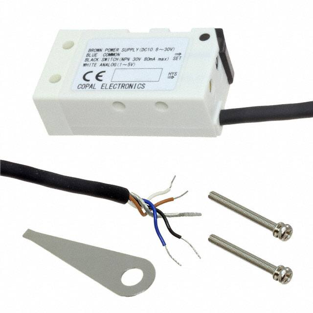
PS40 (NAM, NAR, PAM, PAR)
Wire color
PS40 (NWM, NWR, PWM, PWR)
Connection
Wire color
Connection
Brown
Power B
Brown
Power B
Black
Switch output
Black
Switch output 1
White
Analog output
White
Switch output 2
Blue
Common
Blue
Common
Shield
N.C.
Shield
N.C.
■ INTERNAL ELECTRICAL SCHEMATICS
● NAM, NAR(NPN)
●PAM, PAR(PNP)
LED Indicator
Power B
Power B
Load
Pressure
Sensor
Main circuit
Pressure
S.Output
Main circuit
Sensor
A.Output
A.Output
S.Output
Load
Common
Common
FG
FG
● NWM, NWR(NPN)
1
2
●PWM, PWR(PNP)
LED Indicator
1
2
LED Indicator
Power B
Sensor
Main circuit
Power B
Load
Load
Pressure
S.Output1
S.Output2
Pressure
Sensor
S.Output1
S.Output2
Main circuit
Load
Common
Load
Common
FG
FG
■ SWITCH OUTPUT SCHEMATICS
● PS40- *** G
● PS40-102V
Hysteresis
Hysteresis
ON
ON
OFF
OFF
-100 kPa
Set value
Barometic
pressure
Barometic
pressure
※ * A * is adjustable hysteresis type.
Set value
Rated pressure
�
很抱歉,暂时无法提供与“PS40-103G-NAM”相匹配的价格&库存,您可以联系我们找货
免费人工找货