U-GAGE® Q45U Long-Range Ultrasonic Sensors
Datasheet
Piezoelectric Proximity Mode Sensors with Push Button Programming of Sensing Window Limits – Bipolar Discrete Outputs
•
•
•
•
•
•
•
•
•
•
Ultrasonic proximity detection from 250 mm to 3.0 m (9.8 in to 118 in)
Push-button TEACH-mode programming of sensing window limits
Digital filtering for exceptional immunity to electrical and acoustic noise
12 to 24 V dc operation
Bipolar outputs: one NPN (sinking) and one PNP (sourcing)
ON/OFF presence detection or HIGH/LOW level control are switch selectable
Wide operating temperature range of –25 °C to +70 °C (–13 °F to +158 °F); all
models include temperature compensation
Rugged design for use in demanding sensing environments; rated IEC IP67,
NEMA 6P
Choose models with an integral unterminated 2 m (6.5 ft) or 9 m (30 ft) cable, or
with a Mini-style or M12/Euro-style quick-disconnect connection
External enable/disable feature for remote gating control
Analog models are also available
Models with other ranges are also
available
Models
Connection 1
Q45UBB63BC
2 m (6.5 ft) unterminated cable
Q45UBB63BCQ
5-Pin Mini quick disconnect
Q45UBB63BCQ6
5-Pin M12/Euro-style quick
disconnect
Output Type
Response Time
Bipolar NPN/PNP
Programmable for 40, 80, 320, or
1280 milliseconds
WARNING: Not To Be Used for Personnel Protection
Never use this device as a sensing device for personnel protection. Doing so could lead to serious injury or
death. This device does not include the self-checking redundant circuitry necessary to allow its use in
personnel safety applications. A sensor failure or malfunction can cause either an energized or de-energized
sensor output condition.
Temperature Compensation
All models listed above feature temperature compensation. An increase in air temperature shifts both sensing window limits closer
to the sensor. Conversely, a decrease in air temperature shifts both limits further away from the sensor. The shift is approximately
3.5% of the limit distance for a 20 °C change in temperature.
Temperature compensated models maintain the position of both sensing window limits to within 1% of each limit distance over the
0 °C to +50 °C (+32 °F to +122 °F) range, and to within 2.5% over the full operating range of –25 °C to +70 °C (–13 °F to +158 °F).
Overview
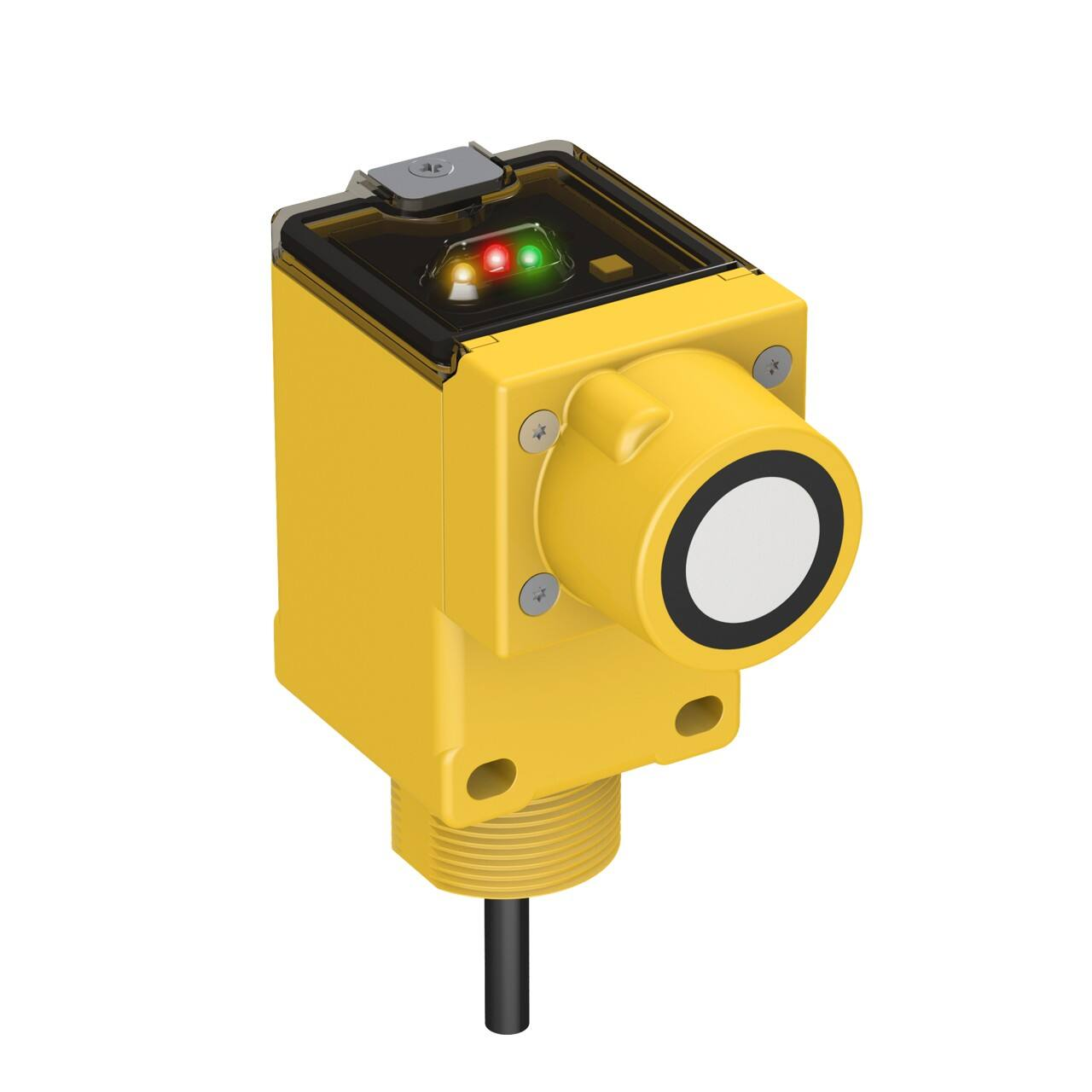
Near and Far Sensing Limit Settings. The Q45U features a single push button for programming the sensing window near and far
limits.
Status Indicators. Status indicator LEDs are visible through the transparent, o-ring sealed polycarbonate top cover. Indicator
function in the Run mode is as follows:
1 To order 9 m (30 ft) cable models, add the suffix “W/30” to the model number of any cabled sensor (for example, Q45UBB63BC W/30).
Models with a quick-disconnect connector require an optional mating cable.
Original Document
48454 Rev. F
19 April 2018
48454
�U-GAGE® Q45U Long-Range Ultrasonic Sensors
•
•
•
The green LED is on when power is applied to the sensor and flashes to indicate an overloaded output.
The red LED flashes when an echo is received; the flash rate is proportional to echo strength.
The amber LED is on when the outputs are conducting.
1.
2.
3.
4.
5.
6.
3
4
1
5
2
Button for programming the sensing window limits
5-Segment target position indicator (N = Near)
Green power indicator
Red signal indicator
Amber output indicator
Slots for removing the inner cover
The 5-segment moving dot LED indicator displays the relative position of
the target within the programmed sensing window. The #1 LED flashes
when the target is closer than the near limit. The #5 LED flashes when the
target is beyond the far limit.
Limits
N
1 2 3 4 5
6
Figure 1. Q45U Long-Range Features
Setting the DIP Switches
Output Response Settings.
Important: Disconnect the power before making any
internal adjustments.
1
ON
2
3
4
1. Insert a small flat-blade screwdriver into the slots.
2. Lift up and remove the black inner cover to expose the 4-position
DIP switch.
3. Use the DIP switches to program the following functions:
Figure 2. Q45U Programming Switches
DIP Switches
Function
ON/OFF Mode
1
2
3 and 4
Output:
On = normally closed (output energizes when target is absent)
Off * = normally open (output energizes when target sensed)
HIGH/LOW Mode
On = Pump Out
Off = Pump In
Mode:
On = HIGH/LOW (fill level control)
Off * = ON/OFF (output follows sensing action)
Response (40 ms/cycle)
Switch 3
Switch 4
1 cycle
OFF
OFF
2 cycles
ON
OFF
8 cycles *
OFF *
ON *
32 cycles
ON
ON
* Factory default setting.
Important: A response setting of 2 cycles, or higher, is recommended for optimum sonic and electrical noise
immunity. Always use the slowest acceptable response speed for your application. Single cycle update is only
recommended for short range (>1.0 m) applications looking for a stationary background target.
2
www.bannerengineering.com - Tel: +1-763-544-3164
P/N 48454 Rev. F
�U-GAGE® Q45U Long-Range Ultrasonic Sensors
Pump-in Application
Pump-out Application
(switch #1 off)
(switch #1 on)
Sensor
Sensor
3
High Level (Near Limit)
2
High Level (Near Limit)
1
Initial Level
1
Initial Level
2
Low Level (Far Limit)
3
Low Level (Far Limit)
Flow
Flow
Pump Control
1
Initial Tank Level - Outputs are INACTIVE
1
Initial Tank Level - Outputs are INACTIVE
2
Level Drops Below Far Limit - Outputs ACTIVE
2
Level Rises Above Near Limit - Outputs ACTIVE
3
Level Rises Above Near Limit - Outputs DEACTIVATE
3
Level Drops Below Far Limit - Outputs DEACTIVATE
Note: If no echo is received by the sensor, the target is assumed to be beyond the far window limit.
Figure 3. High/Low Control (DIP Switch 2 in ON)
The HIGH/LOW mode (DIP switch 2 is ON) provides the switching logic required for fill-level, web tensioning control, and similar
applications. In the HIGH/LOW mode, the output energizes when the target reaches the first sensing window limit, and stays
energized until the target moves to the second limit. The output then de-energizes at the second limit and does not re-energize
until the target moves, again, to the first limit. This example shows how pumping action might be controlled, directly, by the sensor
in a fill-level application.
Programming the Window Limit
Use the Limits button, located under the transparent top cover, to program the near and the far limits.
The near limit may be set as close as 250 mm (9.8 in) and the far limit may be set as far as 3.0 m (118 in) from the transducer face.
The minimum window width is 25 mm (1.0 in). When possible, use the actual target to be sensed when setting the window limits.
Programming the window limit begins with the sensor in Run mode.
1. Push and hold the Limits button until the green LED turns off (approximately 2 seconds).
Green LED
Amber LED
Red LED
Off
On to indicate the sensor is ready to
program the first limit
Flashes to indicate the strength of the
echo; Off if no target is present
2. Set the first limit (near or far) by placing the target at the first limit and pressing the Limits button for less than 2 seconds.
Green LED
Amber LED
Red LED
Off
Flashes at 2 Hz to indicate the sensor is
ready to program the second limit
On for a moment, then resumes flashing to
indicate the strength of the echo
3. Set the second limit (far or near) by placing the target at the second limit and pressing the Limits button for less than 2
seconds.
Green LED
Amber LED
Red LED
Off, then turns on when the sensor returns
to Run mode
On for a moment, then is either on or off to
indicate the output state when the sensor
returns to Run mode
On for a moment, then resumes flashing to
indicate the strength of the echo when the
sensor returns to Run mode
Notes regarding window limit programming:
P/N 48454 Rev. F
www.bannerengineering.com - Tel: +1-763-544-3164
3
�U-GAGE® Q45U Long-Range Ultrasonic Sensors
1. Either the near or far limit may be programmed first.
2. There is a 2-minute timeout for programming of the first limit. The sensor returns to Run mode with the previously
programmed limits. There is no timeout between the programming of the first and second limit.
3. Cancel the programming sequence at any time by pressing and holding the Limits button for ≥ 2 seconds. The sensor
returns to Run mode with the previously programmed limits.
4. During limit programming, the 5-segment moving dot indicator displays the relative target position between 0 m and 4.0 m
(0 ft and 13.1 ft). The maximum recommended far limit position is 3.0 m (9.84 ft).
5. If the target is positioned between 3.0 and 4.0 m (9.84 ft to 13.1 ft), the 5th segment of the moving dot indicator flashes to
indicate that a valid echo is received, but the target is beyond the recommended 3.0 m (9.84 ft) maximum far limit.
6. If a limit is rejected during either programming step, the sensor reverts to the first limit programming step. This is indicated
by the green LED (OFF), red LED (flashing to indicate signal strength), and the amber LED (ON).
7. If both limits are accepted, the sensor returns to Run mode, which is indicated by the green LED (ON).
8. If the target is held at the same position for programming of both limits, the sensor establishes a 50 mm wide sensing
window, centered on the target position.
Specifications
Supply Voltage and Current
12 to 24 V dc (10% maximum ripple) at 100 mA, exclusive of load
Proximity Mode Range
Near limit: 250 mm (9.8 in) minimum
Far limit: 3.0 m (118 in)
Note: The far limit may be extended as far as 3.9 m (12.79 ft) for good
acoustical targets (hard surfaces with an area > 100 cm2)
Supply Protection Circuitry
Protected against reverse polarity and transient voltages
Output Configuration
Bipolar: one current sourcing (PNP) and one current sinking (NPN) opencollector transistor
Use the 4-position DIP switch to select the following:
Switch 1: Output normally open/normally closed (pump in/pump out)
Switch 2: High/Low level control mode or on/off presence sensing
mode
Switch 3 & 4: Response speed selection (digital filter)
Output Rating
150 mA maximum (each)
Off-state leakage current: < 25 microamp at 24 V dc
On-state saturation voltage: < 1.5 V at 10 mA; < 2.0 V at 150 mA
Output Protection Circuitry
Protected against false pulse on power-up and continuous overload or
short-circuit of outputs
Hysteresis
ON/OFF mode: 10 mm
HIGH/LOW mode: 0 mm
Certifications
Performance Specifications
Repeatability: ±0.1% of measured distance (±0.50 mm min)
Minimum Window Width: 25 mm (1.0 in)
Hysteresis: 10 mm (0.4 in)
Indicators
Three status LEDs:
Green ON = power to sensor is ON
Green flashing = output is overloaded
Amber ON = outputs are conducting (in Run mode); or programming
status (in Setup mode)
Red flashing = indicates relative strength of received echo
5-segment moving dot LED indicates the position of the target within the
sensing window
Construction
Molded PBT thermoplastic polyester housing, o-ring sealed transparent
acrylic top cover, and stainless steel hardware.
Q45U sensors are designed to withstand 1200 psi washdown.
The base of cabled models has a 1/2"-14 NPS internal conduit thread
Connections
2 m (6.5 ft) or 9 m (30 ft) attached cable, or 5-pin Mini-style or 5-pin M12/
Euro-style quick disconnect fitting
Environmental Rating
Leakproof design is rated IEC IP67; NEMA 6P
Operating Conditions
Temperature: –25 °C to +70 °C (–13 °F to +158 °F)
Maximum relative humidity: 100%
Vibration and Mechanical Shock
All models meet Mil Std. 202F requirements. Method 201A (vibration: 10 Hz
to 60 Hz max., double amplitude 0.06 inch, maximum acceleration 10G).
Also meets IEC 947-5-2 requirements: 30G 11 ms duration, half sine wave.
Method 213B conditions H & I (Shock: 75G with unit operating; 100G for
non-operation).
Application Notes
Minimum target size: 50 mm × 50 mm aluminum plate at 3.0 m (118 in)
Enable/Disable: Connect the yellow wire to +5 to 24 V dc to enable the
sensor and 0 to +2 V dc to disable the sensor. When the sensor is disabled,
the last output state is held until the sensor is re-enabled. Hold the wire to
the appropriate voltage for at least 40 ms to enable or disable the sensor.
4
www.bannerengineering.com - Tel: +1-763-544-3164
P/N 48454 Rev. F
�U-GAGE® Q45U Long-Range Ultrasonic Sensors
Performance Curves
Effective Beam with 2.5 cm Rod Target (Typical)
400 mm
16 in
400 mm
16 in
300 mm
12 in
300 mm
12 in
200 mm
8 in
200 mm
8 in
100 mm
4 in
100 mm
4 in
0
0
100 mm
4 in
200 mm
Lateral Distance
Lateral Distance
Effective Beam with 100 × 100 mm Plate Target (Typical)
0
0
100 mm
4 in
8 in
200 mm
8 in
300 mm
12 in
300 mm
12 in
400 mm
16 in
4000 mm
160 in
400 mm
0
500 mm
20 in
1000 mm
40 in
1500 mm
60 in
2000 mm
80 in
2500 mm
100 in
3000 mm 3500 mm
120 in
140 in
0
500 mm
20 in
1000 mm
40 in
1500 mm
60 in
Sensing Distance
2000 mm
80 in
2500 mm
100 in
3000 mm 3500 mm
120 in
140 in
16 in
4000 mm
160 in
Sensing Distance
Dimensions
Cabled Models
5-pin Mini-style QD Models
5-pin Euro-style QD Models
Transparent Cover (Gasketed)
View: Sensing Status
Output Load Status
Power
Open to Access:
Push Button for
Programming of Sensing
Window Limits
79.4 mm
(3.13")
44.5 mm
(1.75")
Transducer
Centerline
50.3 mm
(1.98")
69.0 mm
(2.72")
6.4 mm (0.25")
87.6 mm
(3.45")
4.5 mm (#10) Screw
Clearance (2)
7.1 mm
(0.28")
30.0 mm
(1.18")
Hex Nut Supplied
Internal Thread: (1/2 NPSM)
External Thread: (M30 x 1.5)
ø6.1 mm (.24")
2 m (6.5') Cable
15 mm (0.6")
14 mm (0.6")
Wiring Diagrams
Q45U Sensor with 5-pin Mini-style or
Euro-style QD
Q45U Sensor with Attached Cable
1
+
12–24 V dc
−
3
2
4
5
shield
P/N 48454 Rev. F
1
3
2
Load
4
Load
Enable
(+5–24 V dc)
+
12–24 V dc
−
5
shield
Load
Load
Enable
(+5–24 V dc)
www.bannerengineering.com - Tel: +1-763-544-3164
Key
1 = Brown
2 = White
3 = Blue
4 = Black
5 = Gray (Euro-style) or yellow
(Mini-style)
Banner Engineering Corp.
recommends that the shield wire
be connected to earth ground or
dc common.
5
�U-GAGE® Q45U Long-Range Ultrasonic Sensors
Accessories
Cordsets
5-Pin Mini-Style Cordsets—with Shield
Model
Length
Style
MBCC2-506
1.83 m (6 ft)
MBCC2-512
3.66 m (12 ft)
Dimensions
Pinout (Female)
52 Typ.
7/8-16UN-2B
3
1
5
Straight
MBCC2-530
4
2
1 = Brown
2 = White
3 = Blue
4 = Black
5 = Yellow
ø 25.5
9.14 m (30 ft)
5-Pin Threaded M12/Euro-Style Cordsets—with Shield
Model
Length
Style
MQDEC2-506
1.83 m (6 ft)
MQDEC2-515
4.57 m (15 ft)
MQDEC2-530
9.14 m (30 ft)
MQDEC2-550
15.2 m (50 ft)
MQDEC2-506RA
1.83 m (6 ft)
MQDEC2-515RA
4.57 m (15 ft)
MQDEC2-530RA
9.14 m (30 ft)
Dimensions
44 Typ.
Straight
2
M12 x 1
ø 14.5
1
3
4
5
32 Typ.
[1.26"]
1 = Brown
2 = White
3 = Blue
4 = Black
5 = Gray
30 Typ.
[1.18"]
Right-Angle
MQDEC2-550RA
Pinout (Female)
15.2 m (50 ft)
M12 x 1
ø 14.5 [0.57"]
Brackets
SMB30S
•
Swivel bracket with 30 mm
mounting hole for sensor
•
Adjustable captive swivel ball
•
Black reinforced thermoplastic
polyester
•
Stainless steel mounting and
swivel locking hardware
included
63.5 mm
[2.5”]
Not Shown:
(2) M5 x 0.8 x 60 mm
screws are supplied for
clamping bracket together
SMB30C
12.2 mm
[0.48”]
82.5 mm
[3.25”]
30 mm split clamp, black PBT
bracket
•
Stainless steel mounting
hardware included
•
Mounting hole for 30 mm
sensor
43.2 mm
[1.7”]
50.8 mm
[2”]
M5 x 0.8 x 30 mm
Screw (2)
25.4 mm
[1”]
56
•
A
66
B
13
Hole center spacing: A=ø 45
Hole size: B=ø 27.2
6
www.bannerengineering.com - Tel: +1-763-544-3164
P/N 48454 Rev. F
�U-GAGE® Q45U Long-Range Ultrasonic Sensors
SMB30MM
•
12-ga. stainless steel bracket
with curved mounting slots for
versatile orientation
•
Clearance for M6 (¼ in)
hardware
•
Mounting hole for 30 mm
sensor
57
70
C
57
B
A
Hole center spacing: A = 51, A to B = 25.4
Hole size: A = 42.6 x 7, B = ø 6.4, C = ø 30.1
Banner Engineering Corp. Limited Warranty
Banner Engineering Corp. warrants its products to be free from defects in material and workmanship for one year following the date of shipment. Banner Engineering Corp. will repair or
replace, free of charge, any product of its manufacture which, at the time it is returned to the factory, is found to have been defective during the warranty period. This warranty does not
cover damage or liability for misuse, abuse, or the improper application or installation of the Banner product.
THIS LIMITED WARRANTY IS EXCLUSIVE AND IN LIEU OF ALL OTHER WARRANTIES WHETHER EXPRESS OR IMPLIED (INCLUDING, WITHOUT LIMITATION, ANY WARRANTY OF
MERCHANTABILITY OR FITNESS FOR A PARTICULAR PURPOSE), AND WHETHER ARISING UNDER COURSE OF PERFORMANCE, COURSE OF DEALING OR TRADE USAGE.
This Warranty is exclusive and limited to repair or, at the discretion of Banner Engineering Corp., replacement. IN NO EVENT SHALL BANNER ENGINEERING CORP. BE LIABLE TO
BUYER OR ANY OTHER PERSON OR ENTITY FOR ANY EXTRA COSTS, EXPENSES, LOSSES, LOSS OF PROFITS, OR ANY INCIDENTAL, CONSEQUENTIAL OR SPECIAL DAMAGES
RESULTING FROM ANY PRODUCT DEFECT OR FROM THE USE OR INABILITY TO USE THE PRODUCT, WHETHER ARISING IN CONTRACT OR WARRANTY, STATUTE, TORT,
STRICT LIABILITY, NEGLIGENCE, OR OTHERWISE.
Banner Engineering Corp. reserves the right to change, modify or improve the design of the product without assuming any obligations or liabilities relating to any product previously
manufactured by Banner Engineering Corp. Any misuse, abuse, or improper application or installation of this product or use of the product for personal protection applications when the
product is identified as not intended for such purposes will void the product warranty. Any modifications to this product without prior express approval by Banner Engineering Corp will
void the product warranties. All specifications published in this document are subject to change; Banner reserves the right to modify product specifications or update documentation at
any time. Specifications and product information in English supersede that which is provided in any other language. For the most recent version of any documentation, refer to:
www.bannerengineering.com.
© Banner Engineering Corp. All rights reserved
�