Ultrasonic
Diffuse, Analogue Output
Types UA18CSD......TI
• Cylindrical M18 PBT housing
• Sensing distance: 40-800 mm
• Power supply: 10-30 VDC
• Outputs: 0-10 VDC or 4-20 mA
• Linearity error 1%
• Repeatability 1%
• Beam angle. ±7° or ±8°
• Protection: short-circuit and overvoltage
• Protection degree IP 67
• 2 m cable or M12 plug
Product Description
Ordering Key
A family of diffuse ultrasonic
sensors with a sensing range
from 40-300 mm and 80-800
mm with a resolution as low
as 3.0 mm. The sensor contains an analogue output that
is either 0-10 V or 4-20 mA.
This sensor is the ideal choice
Ultrasonic sensor
Housing style
Housing size
Housing material
Housing length
Detection principle
Sensing distance
Output type
Output configuration
Connection
Teach-in
for distance measurement,
level measurement, diameter
measurement or loop control.
Due to the use of microprocessor control the digital filtering makes the sensor
immune to most electromagnetic interferences.
UA18CSD08AGM1TI
Type Selection
Housing
diameter
Connec-
tion
Rated operating
dist. (Sn)
Analogue
Ordering no.
Output
M18
M18
M18
M18
M18
M18
M18
M18
Plug M12
Cable
Plug M12
Cable
Plug M12
Cable
Plug M12
Cable
40-300
40-300
40-300
40-300
80-800
80-800
80-800
80-800
4-20
4-20
0-10
0-10
4-20
4-20
0-10
0-10
mm
mm
mm
mm
mm
mm
mm
mm
mA
mA
V
V
mA
mA
V
V
UA
UA
UA
UA
UA
UA
UA
UA
18
18
18
18
18
18
18
18
CSD
CSD
CSD
CSD
CSD
CSD
CSD
CSD
03
03
03
03
08
08
08
08
AG M1 TI
AG TI
AK M1 TI
AK TI
AG M1 TI
AG TI
AK M1 TI
AK TI
Specifications
Rated operating distance (Sn) Reference target: 1 mm
metal rolled finish
100 x 100 mm
UA18CSD03
40 - 300 mm
UA18CSD08
80 - 800 mm
Blind zone
UA18CSD03...
≤ 40 mm
UA18CSD08...
≤ 80 mm
Repeatability
1%
Linear Accuracy
1%
Beam angle
UA18CSD03...
7° ± 2°
UA18CSD08...
8° ± 2°
Adjustment
Teach by wire
P1 (farthest setpoint)
P2 (nearest setpoint)
Resolution
3 mm
Temperature drift 0.1%/˚C @ -20˚ to +60˚ C
Specifications are subject to change without notice (29.10.2015)
Temperature compensation Yes
Hysteresis (H)
Min. 1%
Rated operational voltage (UB) 10 to 30 VDC
(ripple included)
Ripple (Urpp)
≤ 5%
No-load supply current (Io)
35 mA @ UB max
Protection analogue output Short-circuit and
overvoltage
Output analogue output
AG.. types
4 to 20 mA
AK.. types
0 to 10 VDC
Load
4 to 20 mA
max. 500 Ω
0 to 10 VDC
min. 3 kΩ
Carrier frequency
300 kHz
Response time analogue
output
≤ 400 mS
1
�UA18CSD..
Specifications (cont.)
Power ON delay
≤ 900 mS
Output switching function
Analogue output with posi-
tive or negative slope.
Indication
Output ON
Yellow LED
Echo ON
Green LED
Environment
Installation category
lll (IEC 60664/60664A;
60947-1)
Pollution degree
3 (IEC 60664/60664A;
60947-1)
Degree of protection
IP67 (IEC 60529; 60947-1)
Ambient temperature
Operating
-20° to +60°C (-4° to +140°F)
Storage
-35° to +70°C (-31° to +158°F)
Vibration
10 to 55 Hz, 1.0 mm/6g
(IEC/EN 60068-2-6)
Shock
30 g / 11 mS, 3 directions
(IEC/EN 60068-2-27)
Rated insulation voltage
Housing
Material body
Material front
Material back, plug
Material back, cable
Material sealing front
Connection
Cable
Plug
Tightening torque
Weight
Cable version
Plug version
CE-marking
Approvals
500 VAC (rms)
PBT
Epoxy-glass resin
Grilamid
Grilamid
TPE
PVC, grey, 2 m,
4 x 0.32 mm2, Ø = 4.7 mm
M12, 4-pin (CON. 14-series)
≤ 1 Nm
135 g
65 g
Yes
cULus (UL508)
Detection Range
X
100,0
80,0
60,0
40,0
20,0
0,0
-20,0
-40,0
-60,0
-80,0
-100,0
0
3,9
0
100
UA 18 CSD 03 ...
Distance (Inches)
7,9
11,8
Target
Y
Sensor
15,7
19,7
3,9
3,1
Target 100 x 100 mm
2,4
1,6
Target Ø 25 mm
0,8
0,0
-0,8
-1,6
-2,4
-3,1
-3,9
200
300
400
500
Distance (mm)
Parallel displacement (mm)
Parallel displacement (mm)
Sensor
Parallel displacement (Inches)
Y
100,0
80,0
60,0
40,0
20,0
0,0
-20,0
-40,0
-60,0
-80,0
-100,0
0
3,9
0
200
UA 18 CSD 08 ...
Distance (Inches)
7,9
11,8
400
15,7
19,7
3,9
3,1
Target 100 x 100 mm
2,4
1,6
Target Ø 25 mm
0,8
0,0
-0,8
-1,6
-2,4
-3,1
-3,9
600
800
1000
Parallel displacement (Inches)
X
Target
Distance (mm)
Wiring Diagram
Voltage
Teach
U
BN1
WH2
BK4
BU3
2
Current
Teach
I
BN1
WH2
BK4
BU3
Specifications are subject to change without notice (29.10.2015)
�UA18CSD..
1
38.3
13.6
LED indication
1
21.1
38.3
60.4
52.9
Cable
M12 x 1
LED indication
M18 x 1
M18 x 1
Ø 4.7
Dimensions
Plug
Programming set-up
Teach-in by wire adjustment options
Two Teach-in adjustment options are available:
In the following, “Activate Teach” means:
Connect the white wire to GND (Blue wire)
1) Window Teach-in Option (adjustment of two points: P1 and P2)
Teach-in of set point P1:
• Place the target at the selected far distance P1 - the green Echo LED is ON
• “Activate Teach” shortly
• Setpoint P1 has been stored and the sensor is still in teach mode
• The orange LED will continue flashing rapidly with a frequency of 2 Hz until the setpoint P2 has been learned
Teach-in of set point P2:
• Place the target at the selected close distance P2 - the green Echo LED is still ON
• “Activate Teach” shortly
• The green LED switch OFF and the orange LED will flash 5 times with a frequency of 2,5 Hz
• Setpoint P2 has been stored.
• The sensor is in normal mode and the green and yellow LEDs are steady.
2) Target adjustment on P1 only (Minimum P2 distance)
Teach-in of set point P1:
• Place the target at the selected far distance P1 - the green Echo LED is ON
• “Activate Teach” shortly
• Setpoint P1 has been stored and the sensor is still in teach mode
• The orange LED will continue flashing rapidly with a frequency of 2 Hz until setpoint P2 has been learned
• Without moving the target
• “Activate Teach” shortly
• The green LED switches OFF and the orange LED will flash 5 times with a frequency of 2,5 Hz
• Setpoint P2 has been stored at the minimum distance
• The sensor is in normal mode and the green and yellow LEDs are steady
Specifications are subject to change without notice (29.10.2015)
3
�Programming set-up (cont.)
Configuration of the slope of the analogue output
The analogue version’s default setting is positive slope.
Change configuration from positive to negative slope:
• “Activate Teach” for more than 6 seconds until the orange LED flashes at a high rate/10 times per second.
• Deactivate Teach: The orange LED flashes 5 times, and the output stage is changed.
Analogue
V/mA
10 VDC/
20 mA
P2 P1
V/mA
Distance
Positive slope
10 VDC/
20 mA
P2 P1
Distance
Negative slope
Installation Hints
To avoid interference from inductive voltage/
current peaks, separate the prox. switch
power cables from any other power cables,
e.g. motor, contactor or solenoid cables
Relief of cable strain
Protection of the sensing face
Switch mounted on mobile carrier
A proximity switch should not serve as
mechanical stop
Any repetitive flexing of the
cable should be avoided
Incorrect
Correct
The cable should not be pulled
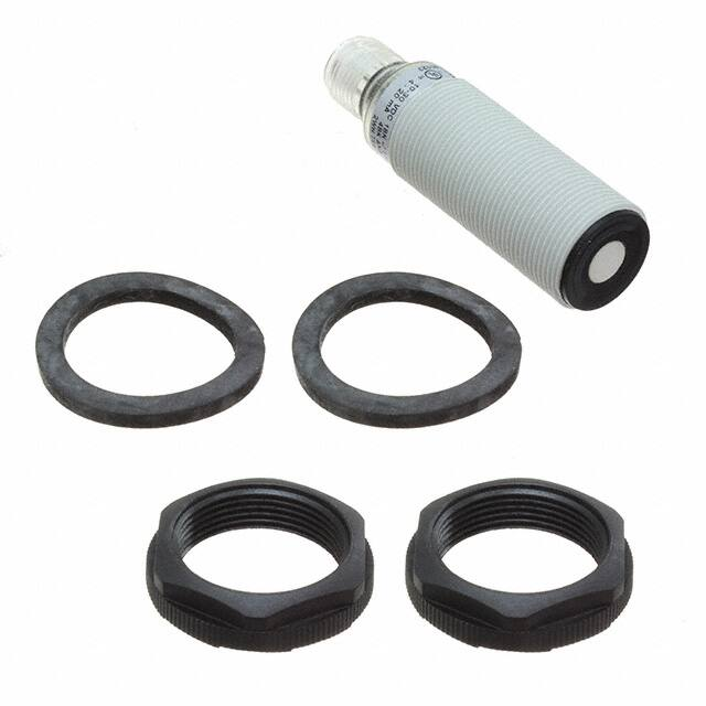
Delivery Contents
• Ultrasonic sensor: UA18CSD....
• Installation instruction
• Mounting:
2 x M18 nuts
2 x rubber washers
• Packaging: Carton box 35 x 107 x 173 mm
4
Specifications are subject to change without notice (29.10.2015)
�


 工商网监
湘ICP备2023018690号
工商网监
湘ICP备2023018690号
