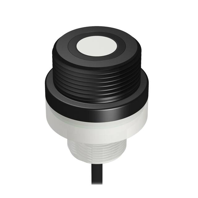
Sure Cross® U-GAGE K50U Ultrasonic Sensor
Datasheet
The Sure Cross® K50U sensor works in a variety of environments to provide a measurement of the distance between the target
and the sensor. It is designed for plug-and-play use with the Wireless Q45U Node (or any other Banner 1-wire serial node), creating
a cost-effective and easy-to-use solution for monitoring remote or mobile tanks and totes.
Benefits
• Monitor wirelessly to avoid long cable runs
• Threaded housing for easy installation
• Easily monitor remote and mobile tanks and totes
• Completely wireless solution with 2+ year battery life at default sample rates
•
•
•
•
•
Provides a distance measurement from the target to the sensor
Built-in temperature compensation
Rugged design for demanding sensing environments; rated IEC IP67, NEMA 6P
Connects using a 1-wire serial interface
Designed to work with FlexPower 1-Wire Serial Interface Node models
DX80N9X1S-P6 and DX80N2X1S-P6, the 10 to 30 V dc powered 1-Wire Serial
Interface Node models DX80N9X6S-P6 and DX80N2X6S-P6, MultiHop M-H6 and
M-H6L radios, and Wireless Q45 Sensor Nodes DX80N2Q45U and DX80N9Q45U
WARNING: Not To Be Used for Personnel Protection
Never use this device as a sensing device for personnel protection. Doing so could lead to serious injury or
death. This device does not include the self-checking redundant circuitry necessary to allow its use in
personnel safety applications. A sensor failure or malfunction can cause either an energized or de-energized
sensor output condition.
Models
Model
K50UX1ARA
K50UX1CRA
Range and Frequency
Supply Voltage
I/O
3.6 to 5.5 V dc or 10
to 30 V dc
Distance to target using
a 1-wire serial interface
Range: 100 mm to 1 m (3.94 in to 39.4 in)
Freq: 224 kHz
Range: 300 mm to 3 m (11.8 in to 118 in)
Freq: 114 kHz
Overview
The K50U is an easy-to-use ultrasonic sensor with extended range and built-in temperature compensation. This sensor is designed
to interface with a Node with 1-Wire Serial Interface. To install the sensor to either the serial Node or a cable, follow these
instructions:
1. Align the notch in the Node’s or cable’s female connector with the key in the sensor’s male connector.
2. Gently slide the sensor end into the Node’s or cable’s connector.
3. Rotate the Node’s or cable’s threaded nut to tighten the sensor down. DO NOT attempt to rotate the sensor after it is
connected to the Node’s serial port or the cable end, this will damage the sensor.
Indicator LEDs communicate the status of the sensor. The flashing green Power LED indicates the sensor is in Run Mode (the
sensor’s normal operating condition).
Configure this sensor using the Sure Cross® Sensor Configuration Tool (instruction manual 170002) and adapter cable BWAUSB1WIRE-001 (datasheet 170020).
Principles of Operation
Ultrasonic sensors emit one or multiple pulses of ultrasonic energy, which travel through the air at the speed of sound. A portion of
this energy reflects off the target and travels back to the sensor. The sensor measures the total time required for the energy to
reach the target and return to the sensor. The distance to the object is then calculated using the following formula: D = ct ÷ 2
Original Document
191599 Rev. F
2 May 2018
191599
�Sure Cross® U-GAGE K50U Ultrasonic Sensor
D = distance from the sensor to the target
c = speed of sound in air
t = transit time for the ultrasonic pulse
To improve accuracy, an ultrasonic sensor may average the results of several pulses before outputting a new value.
Temperature Effects
The speed of sound is dependent upon the composition, pressure and temperature of the gas in which it is traveling. For most
ultrasonic applications, the composition and pressure of the gas are relatively fixed, while the temperature may fluctuate.
In air, the speed of sound varies with temperature according to the following approximation:
In metric units:
In English units:
Cm/s = 20 √273 + TC
Cft/s = 49 √460 + TF
Cm/s = speed of sound in meters per second
Cft/s = speed of sound in feet per second
TC = temperature in °C
TF = temperature in °F
Temperature Compensation
Changes in air temperature affect the speed of sound, which in turn affects the total time for the echo measured by the sensor. An
increase in air temperature shifts both sensing window limits closer to the sensor. Conversely, a decrease in air temperature shifts
both limits farther away from the sensor. This shift is approximately 3.5% of the limit distance for a 20° C change in temperature.
The K50U series ultrasonic sensors are temperature compensated, to reduce sensor errors from temperature by about 90%.
Exposure to direct sunlight can affect the sensor’s ability to accurately compensate for changes in temperature.
LED Indicators
Signal LED (red)
Power LED (green)
Power is Off
Off
Sensor is operating normally (power is on, sensor is in Run mode)
Flashing
Serial Communications Transmit/Receive
Intermittent Flashing
Error
Continuous Flashing
Reserved
Off
Self-Diagnostic Error Mode—In the unlikely event of a microprocessor memory error, the Signal LED continuously flashes. If this
occurs, the setup parameters have been lost and the sensor may be corrupt. Contact your Banner representative for further
information.
Sensor Configuration Tool
The Sensor Configuration Tool offers an easy way to manage sensor parameters, retrieve data, and visually show sensor data from
a number of different sensors. The Sensor Configuration Tool software runs on any Windows machine and uses an adapter cable
to connect the sensor to your computer.
Download the most recent version of the Sensor Configuration Tool from Banner Engineering's website:
www.bannerengineering.com/wireless. The Sensor Configuration Tool currently supports the following sensors:
Sensor Type
Model
USB Adapter Cable
Temperature and Humidity
M12FTH3Q and M12FT3Q
Model BWA-HW-006: USB-to-RS-485 adapter cable OR
Model BWA-UCT-900: USB to RS-485 adapter cable
Vibration and Temperature
M12FTH4Q and M12FT4Q
Model BWA-USB1WIRE-001: USB-to-RS-232 1-Wire adapter cable
QM42VT1
Model BWA-USB1WIRE-001: USB-to-RS-232 1-Wire adapter cable
QM42VT2
Model BWA-HW-006: USB-to-RS-485 adapter cable OR
Model BWA-UCT-900: USB to RS-485 adapter cable OR
When updating the firmware, you must use one of the two USB to RS-485 adapter cables plus a
splitter pigtail cable p/n 83265
2
www.bannerengineering.com - Tel: +1-763-544-3164
P/N 191599 Rev. F
�Sure Cross® U-GAGE K50U Ultrasonic Sensor
Sensor Type
Model
USB Adapter Cable
GPS
GPS50M
Model BWA-HW-006: USB-to-RS-485 adapter cable AND a field-wireable M12/Euro-style
connector or connecter with pigtail OR
Model BWA-UCT-900: USB to RS-485 adapter cable AND a field-wireable M12/Euro-style
connector or connecter with pigtail
U-GAGE K50U Ultrasonic
K50UX1CRA
Model BWA-USB1WIRE-001: USB-to-RS-232 1-Wire adapter cable
K50UX2CRA
Model BWA-HW-006: USB-to-RS-485 adapter cable OR
Model BWA-UCT-900: USB to RS-485 adapter cable
K50UX1ARA
Model BWA-USB1WIRE-001: USB-to-RS-232 1-Wire adapter cable
K50UX2ARA
Model BWA-HW-006: USB-to-RS-485 adapter cable OR
Model BWA-UCT-900: USB to RS-485 adapter cable
Wiring
This sensor is designed to be plugged directly into compatible Nodes. The Node powers the sensor and periodically requests data
using the 1-wire serial interface. Refer to the Class I Division 2 control drawings (p/n 143086) for wiring specifications or limitations.
5-pin M12/Euro-style Connector (Male)
1
2
4
5
3
Pin
Wire Color
Sensor Connection
1
Brown
Power IN (+), 3.6 to 5.5 V dc
2
White
1-Wire serial device select (sinking input to sensing device)
3
Blue
Ground (-)
4
Black
Not used/reserved
5
Gray
1-Wire serial communications
Holding Registers
The temperature = (Modbus register value) ÷ 20. The distance (in) = (Modbus register value) ÷ 100.
I/O Range
Sensor Register
Holding Register Representation
Output Type
Min
Max
Min (Dec)
Max (Dec)
0
65535
0
65535
1
Distance (mm)
2
Temp °C
–1638.4
1638.3
–32768
32767
3
Temp °F
–1638.4
1638.3
–32768
32767
4
Distance (in)
0
655.35
0
65535
Distance readings below 250 mm (9.84 in) for model K50UX1CRA and below 75 mm (2.95 in) for model K50UX1ARA result in a
register value of 0. If no reflection is received because the target is too far away, the register value is an error value of 65535.
Specifications
Supply Voltage
3.6 to 5.5 V dc or 10 to 30 V dc
Current
Default sensing: 180 µA
Disabled sensing: 40 µA
Active comms: 3.3 mA
P/N 191599 Rev. F
Construction
Housing: PBT polyester
Transducer: epoxy/ceramic composite
Indicators
Two LEDs
Connection
Integral 5-pin M12/Euro-style male quick disconnect
www.bannerengineering.com - Tel: +1-763-544-3164
3
�Sure Cross® U-GAGE K50U Ultrasonic Sensor
K50UX1CRA Performance
Sensing range: 300 mm to 3 m (11.8 in to 118 in)
Ultrasonic frequency: 114 kHz
Temperature effect: 0.02% of distance/°C
Resolution: 0.1% of distance (1.5 mm minimum)
Discrete Inputs
One Sinking
Rating: 3 mA max current at 30 V dc
ON Condition: Less than 0.7 V
OFF Condition: Greater than 2 V or open
K50UX1ARA Performance
Sensing range: 100 mm to 1 m (3.94 in to 39.4 in)
Ultrasonic frequency: 224 kHz
Temperature effect: 0.02% of distance/°C
Resolution: 0.1% of distance (1.5 mm minimum)
Discrete Outputs
Discrete Outputs. One NMOS Sinking (Not used)
Discrete Output Rating: Less than 10 mA maximum current at 30 V; ONState Saturation: Less than 0.7 V at 20 mA
Discrete Output ON Condition. Less than 0.7 V
Discrete Output OFF Condition. Open
Communication Hardware
1-wire serial interface
Baud Rates: 9.6k, 19.2k (default), or 38.4k
Data Format: 8 data bits, No parity (default), even parity, or odd parity
1 stop bit
Communication Protocol
Sure Cross DX80 Sensor Node 1-Wire Serial Interface
Compatible Nodes
900 MHz Models
DX80N9X1S-P6
DX80N9X6S-P6
DX80DR9M-H6 and -H6L
DX80N9Q45U
Communications Line
Level Receive ON: Greater than 2 V
Level Receive OFF: Less than 0.7 V
Level Transmit ON: 2.7 to 3 V
Level Transmit OFF: 0 V (pulldown resistor of 10 kOhm)
Environmental Rating1
Leakproof design, rated IEC IP67 (NEMA 6)
2.4 GHz Models
DX80N2X1S-P6
DX80N2X6S-P6
DX80DR2M-H6 and -H6L
DX80N2Q45U
Vibration and Mechanical Shock
All models meet MIL-STD-202F, Method 201A (Vibration: 10 Hz to 60 Hz
maximum, 0.06 inch (1.52 mm) double amplitude, 10G maximum
acceleration) requirements. Also meets IEC 60947-5-2 (Shock: 30G 11 ms
duration, half sine wave) requirements.
Operating Conditions
–40 °C to +70 °C (–40 °F to +158 °F)
95% at +50 °C maximum relative humidity (non-condensing)
Certifications
Dimensions
59.5 mm
[2.34”]
19 mm
[0.75”]
20 mm
[0.79]
27.5 mm
[1.08”]
50 mm
[1.97”]
M30 x 1.5
1 1/4-11.5 NPT
All measurements are listed in millimeters [inches], unless noted otherwise.
1
4
Operating the devices at the maximum operating conditions for extended periods can shorten the life of the device.
www.bannerengineering.com - Tel: +1-763-544-3164
P/N 191599 Rev. F
�Sure Cross® U-GAGE K50U Ultrasonic Sensor
Performance Curves
1 Meter Models
With Plate Target (Typical)
With Rod Target (Typical)
Maximum Target Rotation Angle
30
200
8.0 in
200
8.0 in
150
6.0 in
150
6.0 in
4.0 in
100
100 x 100 mm
50
2.0 in
0
WIDTH (mm)
WIDTH (mm)
100
0
10 x 10 mm
50
2.0 in
25 mm Rod
50
0
150
6.0 in
150
6.0 in
8.0 in
200
8.0 in
400 mm
(16.0 in)
600 mm
(24.0 in)
800 mm
(32.0 in)
1000 mm
(40.0 in)
20
4.0 in
100
200 mm
(8.0 in)
0
10
2.0 in
4.0 in
0
Target Rotation
(Degrees)
2.0 in
100
200
10
4.0 in
0
10 mm Rod
50
20
0
200 mm
(8.0 in)
DISTANCE
400 mm
(16.0 in)
600 mm
(24.0 in)
800 mm
(32.0 in)
30
0
500 mm
(20.0")
1000 mm
(40.0")
1500 mm
(60.0")
2000 mm
(80.0")
2500 mm
(100.0")
3000 mm
(120.0")
Distance
1000 mm
(40.0 in)
DISTANCE
3 Meter Models
With Rod Target (Typical)
Maximum Target Rotation Angle
16"
400 mm
16"
300 mm
12"
300 mm
12"
8"
200 mm
4"
100 mm
200 mm
100 x 100 mm
WIDTH
100 mm
0
WIDTH
400 mm
0
100 mm
4"
200 mm
8"
300 mm
12"
400 mm
16"
3000 mm
(120")
0
600 mm
(24")
1200 mm
(48")
1800 mm
(72")
2400 mm
(96")
25 mm Rod
0
10 mm Rod
20
8"
4"
0
30
100 mm
4"
200 mm
8"
300 mm
12"
TARGET ROTATION
(DEGREES)
With Plate Target (Typical)
10
0
10
20
400 mm
0
600 mm
(24")
DISTANCE
1200 mm
(48")
1800 mm
(72")
2400 mm
(96")
16"
3000 mm
(120")
30
0
500 mm
(20")
1000 mm
(40")
1500 mm
(60")
2000 mm
(80")
2500 mm
(100")
3000 mm
(120")
DISTANCE
DISTANCE
Accessories
Brackets
BWA-BK-004
•
Mounts both the K50U
Ultrasonic sensor and a
Wireless Q45U Node or
DX80 Node
BWA-BK-006
81
•
181
Mounts both the K50U
Ultrasonic sensor and a
Wireless Q45U Node
64
4X Ø6
97
Ø33.5
4X Ø5.2
Ø30
54
54
Euro-Style Cordsets - Double Ended
When using the FlexPower Node with integrated battery, use a double ended cordset. When using a FlexPower Node with external
power supply, use a single ended cordset. If using the communication lines, the cable length cannot exceed 3 meters (10 ft).
P/N 191599 Rev. F
www.bannerengineering.com - Tel: +1-763-544-3164
5
�Sure Cross® U-GAGE K50U Ultrasonic Sensor
5-Pin Threaded M12/Euro-Style Cordsets—Double Ended and Less Than 3 m Long
Model
Length
DEE2R-51D
0.31 m (1 ft)
DEE2R-53D
0.91 m (3 ft)
Style
Dimensions
Pinout
Male
1
40 Typ.
2
4
5
3
Female Straight/
Male Straight
DEE2R-58D
2.44 m (8 ft)
M12 x 1
ø 14.5
Female
2
44 Typ.
1
3
4
M12 x 1
ø 14.5
5
1 = Brown
2 = White
3 = Blue
4 = Black
5 = Green/Yellow
Banner Engineering Corp. Limited Warranty
Banner Engineering Corp. warrants its products to be free from defects in material and workmanship for one year following the date of shipment. Banner Engineering Corp. will repair or
replace, free of charge, any product of its manufacture which, at the time it is returned to the factory, is found to have been defective during the warranty period. This warranty does not
cover damage or liability for misuse, abuse, or the improper application or installation of the Banner product.
THIS LIMITED WARRANTY IS EXCLUSIVE AND IN LIEU OF ALL OTHER WARRANTIES WHETHER EXPRESS OR IMPLIED (INCLUDING, WITHOUT LIMITATION, ANY WARRANTY OF
MERCHANTABILITY OR FITNESS FOR A PARTICULAR PURPOSE), AND WHETHER ARISING UNDER COURSE OF PERFORMANCE, COURSE OF DEALING OR TRADE USAGE.
This Warranty is exclusive and limited to repair or, at the discretion of Banner Engineering Corp., replacement. IN NO EVENT SHALL BANNER ENGINEERING CORP. BE LIABLE TO
BUYER OR ANY OTHER PERSON OR ENTITY FOR ANY EXTRA COSTS, EXPENSES, LOSSES, LOSS OF PROFITS, OR ANY INCIDENTAL, CONSEQUENTIAL OR SPECIAL DAMAGES
RESULTING FROM ANY PRODUCT DEFECT OR FROM THE USE OR INABILITY TO USE THE PRODUCT, WHETHER ARISING IN CONTRACT OR WARRANTY, STATUTE, TORT,
STRICT LIABILITY, NEGLIGENCE, OR OTHERWISE.
Banner Engineering Corp. reserves the right to change, modify or improve the design of the product without assuming any obligations or liabilities relating to any product previously
manufactured by Banner Engineering Corp. Any misuse, abuse, or improper application or installation of this product or use of the product for personal protection applications when the
product is identified as not intended for such purposes will void the product warranty. Any modifications to this product without prior express approval by Banner Engineering Corp will
void the product warranties. All specifications published in this document are subject to change; Banner reserves the right to modify product specifications or update documentation at
any time. Specifications and product information in English supersede that which is provided in any other language. For the most recent version of any documentation, refer to:
www.bannerengineering.com.
© Banner Engineering Corp. All rights reserved
�