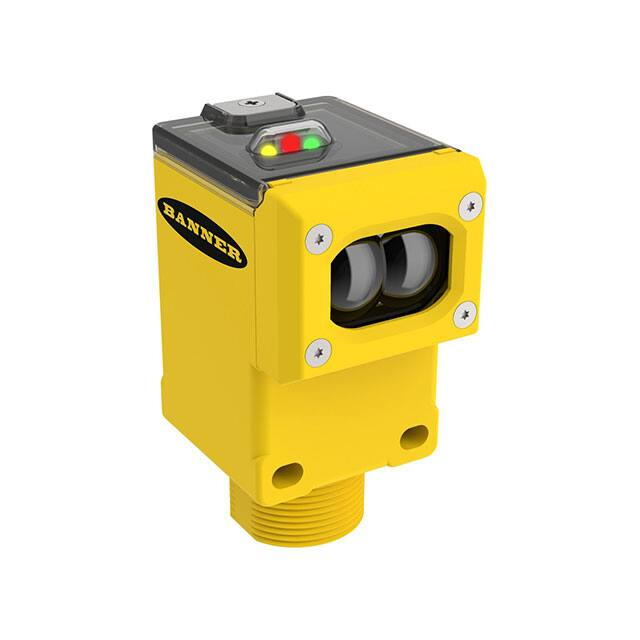
Quick Start Guide for Wireless Q45 Sensor Networks
Formed Using the -QC Gateway
Each sensor is mapped to the one of the Gateway’s outputs by
default. Other mapping options are also supported.
Gateway Model
DX80G2M6-QC
Q45 4
Q45 1
Q45 2
Q45 5
Gateway
outputs 1-6
Q45 3
Q45 6
Each wireless network may have up to six Wireless Q45 Sensor optical models (default configuration) when using the DX80G2M6S-Q
Gateway’s DIP switch-based mapping.
Each Wireless Q45 Sensor is mapped to one of the Gateway’s six discrete outputs.
Step 1: Wire the Gateway’s Outputs
To wire the Gateway’s outputs:
1. Remove the four screws holding the radio cover to the housing base.
2. Wire your outputs according to your network’s configuration.
For additional configuration and Gateway wiring options, refer to the Gateway with Switch Mapping datasheet, part number 161862. To
use more than six sensors (up to 47) in the wireless network, use a Modbus host system (see the Host Configuration manual, Banner p/n
134112).
Use this wiring diagram for the default configuration for Optical Sensor Models: six Q45 Sensors mapped to the six Gateway outputs.
To GND
DI1
DI2
DI3
DI4
DI5
DI6
V+
VV-
Q45 1
Q45 2
Q45 3
Q45 4
Q45 5
Q45 6
DO1
DO2
DO3
DO4
DO5
Load
Load
Load
Load
Load
DO6
Tx/+
Rx/V+
Load
159359
Printed in USA
May 2012
P/N 159359 rev. A
�Quick Start Guide for Q45 Networks
Step 2: Apply Power
Apply Power to the Gateway
V+
V−
Wire Color
Brown
Blue
Gateway
+10 to 30V dc Input
dc common (GND)
Turn on the Wireless Q45 Sensor
To conserve battery power, the Wireless Q45 Sensor ships from the
factory in storage mode. To wake the Q45:
Connecting dc power to the communication pins will
cause permanent damage.
1. Loosen the clamp plate on the top of the Wireless Q45
Sensor and lift the cover.
2. Press and hold the
button for five seconds.
When the Q45 is on, the
red LED flashes.
Button
Step 3: Bind the Wireless Q45 Sensors to the Gateway
Button 2
Binding Wireless Q45 Sensors to their Gateway ensures the Q45s only exchange data with the Gateway they are bound
to. To create your network, bind the Wireless Q45 Sensors to the Gateway and assign them a unique Node address.
1. On the Gateway, triple-click button 2. Both LEDs flash red.
2. On the Gateway, use both rotary dials to assign the Node address for the Q45. Use the left dial for the left digit
and the right dial for the right digit. For example, to assign your Q45 to Node 01, set the left dial to 0 and the
right dial to 1. The Gateway’s LCD displays BINDING and NOD 1. (When using the default Gateway DIP switch
positions, only Nodes 01, 02, and 03 will be mapped to the Gateway’s outputs.)
3. On the Wireless Q45 Sensor, triple-click the button. While in binding mode, the red and green LEDs flash
alternately. After the Q45 is bound, the LEDs flash together four times. The Q45 automatically exits binding
mode.
4. Label the sensor with the Q45’s Node address.
5. Repeat steps 2 through 4 for as many Wireless Q45 Sensors as are needed for your network.
6. On the Gateway, single-click button 2 to exit binding mode.
Rotary dials
Step 4: Verify Radio Communication
To verify the Gateway and Wireless Q45 Sensor are communicating:
• Gateway's LED 1 is solid green.
• Until communication is established with the Gateway, the Q45's red LED flashes.
• After communication is established, the Q45's green LED flashes.
Step 5: Test the Wireless Q45 Sensor Operation
Mount the Wireless Q45 Sensor in your application and view the yellow
LED, which indicates the sensor’s output.
After 15 minutes of inactivity, the LED turns off to conserve power. To
activate the LED, push the button once.
For alignment instructions, refer to the Wireless Q45 Sensor’s datasheet.
Button
Green and red LEDs indicate radio
functions
2 P/N 159359 rev. A
Yellow LED indicates sensor
function
Banner Engineering Corp. • Minneapolis, MN U.S.A
www.bannerengineering.com • Tel: 763.544.3164
�
很抱歉,暂时无法提供与“DX80N9Q45LP”相匹配的价格&库存,您可以联系我们找货
免费人工找货- 国内价格 香港价格
- 1+4085.995471+508.45920
