WORLD-BEAM® QS18 Electronically Adjustable
Background Suppression Sensor (30-250mm)
Datasheet
Compact Sensors Featuring Adjustable Range Background Suppression Mode
•
•
•
•
•
•
•
Two opitcal designs optimized for reliable long-range target detection and stable
detection of colorfully printed packages
◦ High visibility red LED spot AF250 model recommended for long range
detection to 250 mm on black or white targets
◦ Small bright red LED spot AF120 model recommended for reliable detection of
colorfully printed packages and small parts or features
Simple single-turn potentiometer adjustment of cutoff distance
Enhanced immunity to fluorescent lights
Crosstalk immunity algorithm allows two sensors to be used in close proximity
High-intensity, bright red LED spot makes sensor alignment fast and easy
Convenient mounting options available for 18 mm barrel or side mount
Bright indicator LEDs show operating status from 360˚
WARNING: Not To Be Used for Personnel Protection
Never use this device as a sensing device for personnel protection. Doing so could lead to serious injury or
death. This device does not include the self-checking redundant circuitry necessary to allow its use in
personnel safety applications. A sensor failure or malfunction can cause either an energized or de-energized
sensor output condition.
Models
Model1
Output Type
QS18VN6AF250
Complementary NPN
QS18VP6AF250
Complementary PNP
QS18K6AF250Q8
Sensing Range
Adjustable Cutoff: 30 mm to 250 mm
IO-Link
QS18VN6AF120
Complementary NPN
QS18VP6AF120
Complementary PNP
QS18K6AF120Q8
Supply Voltage
10 V dc to 30 V dc
Adjustable Cutoff: 30 mm to 120 mm
IO-Link
Overview
The WORLD-BEAM® QS18 Sensor with Background Suppression detects targets within the cutoff distance while ignoring objects
in the background. Background suppression mode is recommended when target position is repeatable, but target color and
background conditions vary.
1
2
3
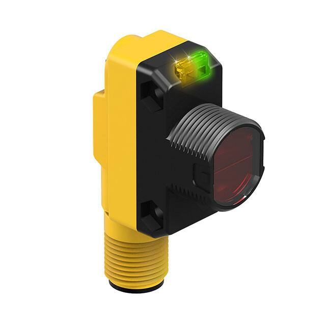
Key
1 Green LED: Power Indicator
2 Amber LED: Light Sensed Indicator (Flashes for Marginal Conditions)
3 Cutoff Point Adjustment Potentiometer
1 2 m (6.5 ft) PVC cabled models are listed for the complementary output models. 2 m (6.5 ft) and 9 m (30 ft) PVC cabled options are not available on IO-Link
models.
•
To order the 9 m (30 ft) PVC cable model, add the suffix "W/30" to the cabled model number. For example, QS18VN6AF250 W/30.
•
To order the 4-pin M12/Euro-style integral quick disconnect model, add the suffix "Q8" to the model number. For example, QS18VN6AF250Q8.
•
To order the 4-pin M8/Pico-style integral quick disconnect model, add the suffix "Q7" to the model number. For example, QS18VN6AF250Q7.
•
To order the 150 mm (6 in) PVC cable model with a 4-pin M12/Euro-style quick disconnect, add the suffix "Q5" to the model number. For
example, QS18VN6AF250Q5.
•
To order the 150 mm (6 in) PVC cable model with a 4-pin M8/Pico-style quick disconnect, add the suffix "Q" to the model number. For example,
QS18VN6AF250Q.
•
Models with a quick disconnect require a mating cordset.
Original Document
201339 Rev. C
11 September 2018
201339
�WORLD-BEAM® QS18 Electronically Adjustable Background Suppression Sensor (30-250mm)
Installation Instructions
Sensor Orientation
Optimize detection reliability and minimum object
separation performance with correct sensor-to-target
orientation. To ensure reliable detection, orient the
sensor as shown in relation to the target to be
detected.
Figure 1. Optimal Orientation of Target to Sensor
Wiring Diagrams
3
–
10-30V dc
+
1
4
2
PNP Output
Load
Load
1
+
10-30V dc
–
3
4
2
IO-Link with PNP Output
Load
1
PUSH-PULL
NPN Output
Load
4
+
CH1
Load
3
2
10-30V dc
Key
1 = Brown
2 = White
3 = Blue
4 = Black
–
CH2
Load
Cabled wiring diagrams are shown. Quick disconnect wiring diagrams are functionally identical.
Sensor Setup
Background Suppression Mode: Objects beyond the set cutoff distance will not be detected. Background suppression mode can
be used in most situations with varying object colors and positions or with varying background conditions.
To ensure reliable background suppression, a minimum separation distance between the object and the background is necessary.
See Figure 3 on page 4 for AF250 models or Figure 4 on page 4 for AF120 models to determine the minimum separation
distance.
1. Mount the sensor with the darkest object at the longest application
Object
Background
distance. The distance to the object must be less than shown in
Figure 3 on page 4, or Figure 4 on page 4 for your object
color, depending on the model.
2. Turn the adjustment potentiometer counter-clockwise until the
yellow indicator turns off.
Y
3. Turn the adjustment potentiometer clockwise until the yellow
X
indicator turns on.
4. Replace the darkest object with the brightest background at the
closest application distance.
Cutoff
5. Turn the adjustment potentiometer clockwise until the yellow
Distance
indicator turns on.
Figure 2. Minimum Separation Distance
6. Turn the adjustment potentiometer counter-clockwise approximately
X:
Distance
to the Object
half of the adjustment rotation from step 5. This places the cutoff
distance approximately half-way between the object and the
Y: Minimum Separation Between the Object and
background switch points.
the Background
If sufficient separation exists between the object and background,
Set the cutoff distance approximately midway
the sensor is ready for operation.
between the farthest object and the closest
background
2
www.bannerengineering.com - Tel: +1-763-544-3164
P/N 201339 Rev. C
�WORLD-BEAM® QS18 Electronically Adjustable Background Suppression Sensor (30-250mm)
IO-Link Interface
IO-Link is a point-to-point communication link between a master device and sensor. It can be used to automatically parameterize
sensors and transmit process data. For the latest IO-Link protocol and specifications, please visit the web site at http://www.iolink.com.
The IO-Link IODD package (P/N 206635) is contained on the Banner Website at http://www.bannerengineering.com.
Specifications
Supply Voltage
10 V dc to 30 V dc (10% maximum ripple within specified limits)
Maximum Power Consumption (exclusive of load)
AF120 Models less than 300 mW
AF250 Models less than 475 mW
Output Response
1.7 milliseconds ON; 1.1 milliseconds OFF
Note: 200 millisecond delay on power-up; outputs do not conduct during this
time
Adjustments
Single-turn adjustment potentiometer sets the cutoff distance between minimum
and maximum positions
Sensing Beam
Visible red LED, 640 nm
Repeatability
130 µs (standard mode)
Supply Protection Circuitry
Protected against reverse polarity and transient voltages
Output Configuration
Solid-state complementary: NPN or PNP, or push/pull, depending on
model
Rating: 50 mA per output
Output Voltage High: Greater than Vsupply - 2.5 V
Output Voltage Low: Less than 2.5 V
For loads less than 1 Meg Ohm
Protected against false pulse on power-up and continuous overload or
short circuit of outputs
Connections
2 m (6.5 ft) unterminated 4-wire PVC cable; 9 m (30 ft) unterminated 4wire PVC cable; 150 mm (6 in) PVC cable with a 4-pin M8/Pico-style
quick disconnect; 150 mm (6 in) PVC cable with a 4-pin M12/Euro-style
quick disconnect; Integral 4-pin M8/Pico-style quick disconnect or
Integral 4-pin M12/Euro-style quick disconnect, depending on model
Models with a quick disconnect require a mating cordset
IO-Link Interface
Supports Smart Sensor Profile: Yes
Baud Rate: 38400 bps
Process Data Widths: 16 bits
IODD Files: Provides all programming options plus additional
functionality; please see the IO-Link Data Reference Guide for more
details
Indicators
2 LED indicators on sensor top:
Green solid: Power on
Amber: Light sensed
Amber flashing: Marginal sensing condition
Construction
ABS housing, acrylic lens cover, nickel-plated brass connector, acetal
adjustment pot
Required Overcurrent Protection
WARNING: Electrical connections must be made by
qualified personnel in accordance with local and
national electrical codes and regulations.
Overcurrent protection is required to be provided by end product application per
the supplied table.
Overcurrent protection may be provided with external fusing or via Current
Limiting, Class 2 Power Supply.
Supply wiring leads < 24 AWG shall not be spliced.
For additional product support, go to www.bannerengineering.com.
Environmental Rating
IEC IP67; NEMA 6; UL Type 1
Operating Conditions
95% relative humidity at 50 °C (non-condensing)
–40 °C to +60 °C (–40 °F to +140 °F)
Certifications
Supply Wiring (AWG)
Required Overcurrent Protection (Amps)
20
5.0
22
3.0
24
2.0
26
1.0
28
0.8
30
0.5
Dimensions
31.0 mm
(1.22")
15.0 mm
(0.59")
17.1 mm
(0.67")
Yellow
LED
Green
LED
3.0 mm
(0.12")
Single-turn
Sensitivity
Adjustment
24.1 mm
(0.95")
35.0 mm
(1.38")
M18x1 Thread
Max. torque 2.3 Nm (20 in-lbs)
Ø3.3 mm (0.13")
Max. torque 0.6 Nm (5 in-lbs)
P/N 201339 Rev. C
www.bannerengineering.com - Tel: +1-763-544-3164
3
�WORLD-BEAM® QS18 Electronically Adjustable Background Suppression Sensor (30-250mm)
Model Suffix Q
(e.g. QS18VN6AF250Q)
Model Suffix Q5
Model Suffix Q7
(e.g. QS18VN6AF250Q5)
(e.g. QS18VN6AF250Q7)
Model Suffix Q8
(e.g. QS18VN6AF250Q8)
41.5 mm
(1.63")
150 mm (6")
Euro-style
Pigtail
150 mm (6")
Pico-Style
Pigtail
49 mm
(1.93")
Integral
4-pin
Pico-Style QD
Integral
4-pin
Euro-Style QD
Performance Curves
Long Range: The minimum sensing range is 8 mm for 6% reflectivity.
Short Range: The minimum sensing range is 13 mm for 6% reflectivity.
AF250 Models
AF120 Models
12
Minimum Separation
Object to Background, Dimension “Y” (mm)
Minimum Separation
Object to Background, Dimension “Y” (mm)
60
Object/Background
50
black/white
40
30
20
gray/white
10
white/white
0
0
25
30
50
75
100
125
150
175
200
225
Object/Background
10
8
black/white
6
4
gray/white
2
white/white
0
250
0
20
Distance to Object, Dimension “X” (mm)
30
40
60
80
100
120
Distance to Object, Dimension “X” (mm)
Figure 3. Minimum Separation Between Object to Background (Background
Suppression Mode)
Figure 4. Minimum Separation Between Object to Background (Background
Suppression Mode)
AF250 and AF120 Models
Emitter Beam Diameter (mm)
20
250 mm
15
10
5
120 mm
0
0
50
100
150
200
250
Range (mm)
Figure 5. Typical Emitter Spot Diameter vs. Distance
4
www.bannerengineering.com - Tel: +1-763-544-3164
P/N 201339 Rev. C
�WORLD-BEAM® QS18 Electronically Adjustable Background Suppression Sensor (30-250mm)
Accessories
Brackets
SMB18A
•
Right-angle mounting
bracket with a curved slot
for versatile orientation
•
12-ga. stainless steel
•
18 mm sensor mounting
hole
•
Clearance for M4 (#8)
hardware
30
C
A
41
B
46
SMBQS18Y
•
Die-cast bracket for 18
mm holes
•
Includes metal hex nut
and lock washer
•
Allows ± 8° for cabled
sensors
2x 8
3.4 mm
[0.13"]
15.5 mm
[0.61"]
4.5 mm
[0.18"]
2x R24.1 mm
[0.95"]
7.8 mm
[0.31"]
24.1 mm
[0.94"]
38.0 mm
[1.50"]
Hole size: A = ø 15.3
12.0 mm
[0.47"]
25.4 mm
[1"]
Hole center spacing: A to B = 24.2
Hole size: A = ø 4.6, B = 17.0 × 4.6, C = ø 18.5
16.4 mm
[0.65"]
9.8 mm
[0.38"]
19.5 mm
[0.77"]
14.5 mm
[0.57"]
SMBQ4X..
•
Swivel bracket with tilt and
pan movement for
precision adjustment
•
Easy sensor mounting to
extruded rail T-slots
•
Metric and inch size bolts
available
•
Side mounting of some
sensors with the 3 mm
screws included with the
sensor
40
43
B
A
SMB18AFA..
•
Protective, swivel bracket
with tilt and pan
movement for precision
adjustment
•
Easy sensor mounting to
extruded rail T-slots
•
Metric and inch size bolts
available
•
Mounting hole for 18 mm
sensors
44
51
ø18.1
3/8-16
UNC
X 2 in.
51
ø19.8
Hole size: B = ø 18.1
B = 7 × M3 × 0.5
Model
Bolt Thread (A)
SMBQ4XFA
3/8 - 16 × 2¼ in
SMBQ4XFAM10
M10 - 1.5 × 50
SMBQ4XFAM12
n/a; no bolt included. Mounts
directly to 12 mm (½ in) rods
Model
Bolt Thread (A)
SMB18AFA
3/8 - 16 × 2 in
SMB18AFAM10
M10 - 1.5 × 50
SMB312S
•
B
Stainless steel 2-axis,
side-mount bracket
46
C
A
32
20
A = 4.3 × 7.5, B = diam. 3, C = 3 ×
15.3
P/N 201339 Rev. C
www.bannerengineering.com - Tel: +1-763-544-3164
5
�WORLD-BEAM® QS18 Electronically Adjustable Background Suppression Sensor (30-250mm)
Cordsets
4-Pin Threaded M12/Euro-Style Cordsets
Model
Length
MQDC-406
1.83 m (6 ft)
MQDC-415
4.57 m (15 ft)
MQDC-430
9.14 m (30 ft)
MQDC-450
15.2 m (50 ft)
MQDC-406RA
1.83 m (6 ft)
MQDC-415RA
4.57 m (15 ft)
MQDC-430RA
9.14 m (30 ft)
Style
Dimensions
Pinout (Female)
44 Typ.
Straight
M12 x 1
ø 14.5
2
1
3
4
32 Typ.
[1.26"]
1 = Brown
2 = White
30 Typ.
[1.18"]
Right-Angle
3 = Blue
4 = Black
MQDC-450RA
15.2 m (50 ft)
M12 x 1
ø 14.5 [0.57"]
4-Pin Threaded M8/Pico-Style Cordsets
Model
Length
PKG4M-2
2 m (6.56 ft)
PKG4M-5
5 m (16.4 ft)
Style
Dimensions
35 Typ.
Straight
PKG4M-9
9 m (29.5 ft)
PKW4M-2
2 m (6.56 ft)
PKW4M-5
ø 9.5
M8 x 1
4
2
1
3
28 Typ.
5 m (16.4 ft)
20 Typ.
Right Angle
PKW4M-9
Pinout (Female)
9 m (29.5 ft)
1 = Brown
2 = White
3 = Blue
4 = Black
M8 x 1
ø 9.5
Banner Engineering Corp. Limited Warranty
Banner Engineering Corp. warrants its products to be free from defects in material and workmanship for one year following the date of shipment. Banner Engineering Corp. will repair or
replace, free of charge, any product of its manufacture which, at the time it is returned to the factory, is found to have been defective during the warranty period. This warranty does not
cover damage or liability for misuse, abuse, or the improper application or installation of the Banner product.
THIS LIMITED WARRANTY IS EXCLUSIVE AND IN LIEU OF ALL OTHER WARRANTIES WHETHER EXPRESS OR IMPLIED (INCLUDING, WITHOUT LIMITATION, ANY WARRANTY OF
MERCHANTABILITY OR FITNESS FOR A PARTICULAR PURPOSE), AND WHETHER ARISING UNDER COURSE OF PERFORMANCE, COURSE OF DEALING OR TRADE USAGE.
This Warranty is exclusive and limited to repair or, at the discretion of Banner Engineering Corp., replacement. IN NO EVENT SHALL BANNER ENGINEERING CORP. BE LIABLE TO
BUYER OR ANY OTHER PERSON OR ENTITY FOR ANY EXTRA COSTS, EXPENSES, LOSSES, LOSS OF PROFITS, OR ANY INCIDENTAL, CONSEQUENTIAL OR SPECIAL DAMAGES
RESULTING FROM ANY PRODUCT DEFECT OR FROM THE USE OR INABILITY TO USE THE PRODUCT, WHETHER ARISING IN CONTRACT OR WARRANTY, STATUTE, TORT,
STRICT LIABILITY, NEGLIGENCE, OR OTHERWISE.
Banner Engineering Corp. reserves the right to change, modify or improve the design of the product without assuming any obligations or liabilities relating to any product previously
manufactured by Banner Engineering Corp. Any misuse, abuse, or improper application or installation of this product or use of the product for personal protection applications when the
product is identified as not intended for such purposes will void the product warranty. Any modifications to this product without prior express approval by Banner Engineering Corp will
void the product warranties. All specifications published in this document are subject to change; Banner reserves the right to modify product specifications or update documentation at
any time. Specifications and product information in English supersede that which is provided in any other language. For the most recent version of any documentation, refer to:
www.bannerengineering.com.
© Banner Engineering Corp. All rights reserved
�