D12 Series DIN Rail High Power Fiber Optic Sensor
Datasheet
Powerful Self-Contained Sensors for Use with Glass or Plastic Fiber Optic Assemblies
•
•
•
•
•
•
•
•
Fiber optic sensors for DIN rail mounting; cabled or quick disconnect (QD)
Fast response: 500 μs standard, 50 μs for Y & Y1 models
Visible red light source; models for use with either glass or plastic fibers
Choice of either NPN (sinking) or PNP (sourcing) complementary outputs; 150 mA maximum
(continuous) load
Normally closed output of most models may be wired as a diagnostic alarm output (depending
upon hookup to power)
Sensors operate from 10 V dc to 30 V dc
LED indicators for Power On and N.O. Output Conducting
7-segment LED bargraph indicates received signal strength, output overload, and marginal excess
gain
WARNING: Not To Be Used for Personnel Protection
Never use this device as a sensing device for personnel protection. Doing so could lead to serious injury or death. This device
does not include the self-checking redundant circuitry necessary to allow its use in personnel safety applications. A sensor failure
or malfunction can cause either an energized or de-energized sensor output condition.
CAUTION: Electrostatic Discharge (ESD)
ESD Sensitive Device. Use proper handling procedures to prevent ESD damage to these devices. The module does not contain any
specific ESD protection beyond the structures contained in its integrated circuits. Proper handling procedures should include
leaving devices in their anti-static packaging until ready for use; wearing anit-static wrist straps; and assembling units on a
grounded, static-dissipative surface.
Models
Glass Fiber Optic Sensors
Models1
Output Type
Response Speed
D12SN6FV(Q)
NPN
Standard 500 μs response time
D12SN6FVY(Q)
NPN
Selectable 50 μs high speed response mode
D12SN6FVY1(Q)
NPN
Selectable 50 μs high speed response mode and 20 ms pulse stretcher
D12SP6FV(Q)
PNP
Standard 500 μs response time
D12SP6FVY(Q)
PNP
Selectable 50 μs high speed response mode
D12SP6FVY1(Q)
PNP
Selectable 50 μs high speed response mode and 20 ms pulse stretcher
Models1
Output Type
Response Speed
D12SN6FP(Q)
NPN
Standard 500 μs response time
D12SN6FPY(Q)
NPN
Selectable 50 μs high speed response mode
D12SN6FPY1(Q)
NPN
Selectable 50 μs high speed response mode and 20 ms pulse stretcher
D12SP6FP(Q)
PNP
Standard 500 μs response time
D12SP6FPY(Q)
PNP
Selectable 50 μs high speed response mode
D12SP6FPY1(Q)
PNP
Selectable 50 μs high speed response mode and 20 ms pulse stretcher
Range
See the performance curves
Plastic Fiber Optic Sensors
Range
See the performance curves
Overview
D12 sensors are compact, self-contained visible-red fiber optic sensors for DIN rail mounting. D12 sensors are designed for use with Banner glass and cutto-length plastic fiber optics. Standard D12FP and D12FV plastic and glass fiber optic sensors offer fast 0.5 millisecond (500 μs) response. D12FVY Series
and D12FPY Series sensors have switch-selectable 50 μs/500 μs response modes for applications that require a faster, high speed response time.
D12FVY1 and D12FPY1 models have switch-selectable response times along with a built-in 20 ms pulse stretcher for use with loads (or input circuits) that
are too slow to react to quick sensing events when using the 50 μs response mode.
1 Include "Q" in model suffix to specify 6-inch cable with 4-pin pico-style QD. Omit "Q" to specify models with 6-foot attached cable. Models with 30-foot attached cable are available.
Original Document
32822 Rev. G
11 September 2017
32822
�D12 Series DIN Rail High Power Fiber Optic Sensor
All models operate from 10 V dc to 30 V dc. D12 sensors are available with a choice of NPN or PNP complementary outputs (one output normally open,
one output normally closed). The normally closed output of FP and FV models (only) may be used as a diagnostic alarm output, depending on the wiring
of the sensor to the power supply. All models are available with either an attached cable or a 6-inch cable with a pico-style quick disconnect connector.
Plastic fiber models may be used with either the small diameter (0.254 mm and 0.508 mm/0.010 inch and 0.020 inch) or the large diameter (1.06 mm/
0.040 inch) Banner cut-to-length plastic fibers.
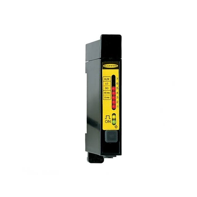
LED Indicators
Two top-mounted LED indicators:
• Green = dc power on
• Amber = Normally Open Output Conducting
Seven-Segment Moving-Dot LED Bargraph
On all D12 sensors operating in the 500 μs (standard) response mode, a red sevensegment moving-dot LED bargraph illuminates to indicate the relative strength of
the received light signal. This feature simplifies the sensitivity adjustment and fiber
optic alignment, and provides a constant reference over time for overall sensing
system performance.
In all models and in both response modes, segment #1 of the bargraph flashes to
indicate an output overload.
On all sensors operating in the 500 μs response mode, segment #7 flashes to
indicate marginal excess gain.
On standard (FP and FY) models, a flashing LED corresponds to the On state of the
D12's alarm output.
Note: The seven segment bargraph and marginal
excess gain indication (segment #7) are inoperative in
the 50 μs response mode on Y and Y1 models.
Sensivity Control
D12s have a 15-turn sensitivity control, with a slotted brass screw clutched at both
ends of travel.
Figure 1. Features
Installing Glass Fibers
1. Gently seat an o-ring onto each sensor end of the fiber.
Sensor end, glass fiber
O-ring (supplied with fiber)
Groove
2. Slide the sensor ends into the fiber ports as far as they will go.
3. Push firmly on the fiber ends to compress the o-ring, and while holding the sensor ends snugly in place, slide the fiber retaining clip into the slot.
4. Press the retaining clip in until it snaps into the groove.
Installing Plastic Fibers
1. Cut the fiber ends according to the instructions included with the fibers.
2. Slide the fiber gripper up (open).
3. If you are using 0.254 mm or 0.508 mm (0 .010 inch or 0.020 inch) diameter fibers: Insert the adaptor into the ports as far as it will go.
Fiber adapter
4. For all fiber diameters: Insert the prepared plastic fiber sensor ends gently into the ports as far as they will go.
5. Slide the fiber gripper back down to lock it.
2
www.bannerengineering.com - Tel: +1-763-544-3164
P/N 32822 Rev. G
�D12 Series DIN Rail High Power Fiber Optic Sensor
Wiring Diagrams
NPN (Sinking) Standard Wiring
3
2
1
–
10-30V dc
+
1
4
NPN (Sinking) Alarm Wiring
4
Load
2
Load
PNP (Sourcing) Standard Wiring
1
4
2
Load
Alarm
PNP (Sourcing) Alarm Wiring
3
+
10-30V dc
–
3
–
10-30V dc
+
3
+
10-30V dc
–
1
4
Load
2
Load
Load
Alarm
Specifications
Sensing Range
See the excess gain curves; Performance Curves—Glass Fiber Optic Sensors on page 5
and Performance Curves—Plastic Fiber Optic Sensors on page 5
Sensing Beam
Visible red, 680 nm
Supply Voltage
10 V dc to 30 V dc at 45 mA maximum, exclusive of load
Protected against reverse polarity and inductive load transients
Output Configurations
Solid-state dc complementary outputs; see the models table for details.
The normally closed (N.C.) output of standard FP and FV models may be used as an alarm
output, depending upon the hookup to the power supply.
Output Rating
Complementary outputs, one normally open (N.O.) and the other normally closed (N.C.).
150 mA maximum each output. No false pulse on power-up. (False pulse protection
circuit causes a 0.1 second delay on power-up.) Short-circuit protected.
Off-state leakage current
很抱歉,暂时无法提供与“D12SP6FP”相匹配的价格&库存,您可以联系我们找货
免费人工找货