A-GAGE® MINI-ARRAY® Measuring Light
Screen System
Instruction Manual
Original Instructions
43298 Rev. H
27 August 2019
© Banner Engineering Corp. All rights reserved
43298
�A-GAGE® MINI-ARRAY® Measuring Light Screen System
Contents
1 Features
..........................................................................................................................................................................3
1.1 MINI-ARRAY Models
2 Overview
...................................................................................................................................................................... 4
.........................................................................................................................................................................6
2.1 System Features
............................................................................................................................................................................. 7
2.2 Sensing Response
.......................................................................................................................................................................... 7
2.3 Supplied System Software
............................................................................................................................................................. 7
3 Specifications
................................................................................................................................................................. 9
3.1 Specifications for the Emitter/Receiver Pairs
................................................................................................................................. 9
3.2 Dimensions for the Emitters and Receivers
.....................................................................................................................................9
3.3 Specifications for the MAC Controllers
......................................................................................................................................... 10
3.4 Dimensions for the Controller
....................................................................................................................................................... 11
4 Installation Instructions
.................................................................................................................................................12
4.1 Emitter and Receiver Mounting
..................................................................................................................................................... 12
4.2 Controller Mounting
...................................................................................................................................................................... 13
4.3 Emitter and Receiver Wiring
......................................................................................................................................................... 13
4.4 Controller and Output Wiring
........................................................................................................................................................ 13
4.4.1 MAC-1 Controller Wiring
....................................................................................................................................................... 13
4.4.2 MACP-1 Controller Wiring
.....................................................................................................................................................14
4.4.3 MACN-1 Controller Wiring
.....................................................................................................................................................14
4.4.4 MACV-1 Controller Wiring
..................................................................................................................................................... 15
4.4.5 MACI-1 Controller Wiring
...................................................................................................................................................... 15
4.4.6 MAC16P-1 Controller Wiring
.................................................................................................................................................16
4.4.7 MAC16N-1 Controller Wiring
.................................................................................................................................................16
4.5 System Power Wiring
....................................................................................................................................................................17
4.6 Gate Wiring
................................................................................................................................................................................... 17
4.7 Serial Communication Wiring
....................................................................................................................................................... 17
5 Configuration Instructions
............................................................................................................................................ 18
5.1 Install the Software
....................................................................................................................................................................... 18
5.2 Define the Communication
........................................................................................................................................................... 18
5.3 Alignment
....................................................................................................................................................................................... 18
5.4 Parameter Setup Files (PSFs)
....................................................................................................................................................... 19
5.4.1 Assigning the Analysis Mode
................................................................................................................................................ 20
5.4.2 Configuring the Outputs
........................................................................................................................................................ 21
5.4.3 Configuring the Blanking Specifications
................................................................................................................................ 24
5.4.4 Configuring the Scanning Method
........................................................................................................................................ 24
5.4.5 Configuring the Control Mode
...............................................................................................................................................25
5.4.6 Configuring the Serial Communication
................................................................................................................................. 25
5.4.7 PSF Assignment and Storage
............................................................................................................................................... 26
6 Operating Instructions
.................................................................................................................................................. 28
6.1 Status Indicators for the MINI-ARRAY Sensors
........................................................................................................................... 28
6.2 Status Indicators for the MACx-1 Series Controllers
....................................................................................................................28
6.3 Diagnostics Program
.................................................................................................................................................................... 29
7 Additional Information
.................................................................................................................................................. 31
7.1 Host Mode Command
.................................................................................................................................................................. 31
7.2 Serial Data Format
........................................................................................................................................................................ 31
7.3 ASCII Format Data Transmission
..................................................................................................................................................31
7.4 Binary Format Data Transmission
.................................................................................................................................................32
8 Accessories
................................................................................................................................................................... 33
8.1 Anti-Vibration Mounting Kits
.........................................................................................................................................................33
9 Product Support and Maintenance
.............................................................................................................................. 34
9.1 Contact Us
.....................................................................................................................................................................................34
9.2 Banner Engineering Corp. Limited Warranty
................................................................................................................................ 34
�A-GAGE® MINI-ARRAY® Measuring Light Screen System
1 Features
•
•
•
•
•
•
•
•
•
•
Measuring Light Screen system for inspection and profiling applications
Modular system with compact controller and a variety of BMEL/BMRL series
MINI-ARRAY emitters and receivers
Sensors available with either 9.5 mm (3/8 in) or 19.1 mm (3/4 in) beam spacing
and with array lengths from 6 in to 4 ft (in 6 in increments), plus 5 ft and 6 ft
models
Controller is programmable for any one or two of ten measurement modes
(depending on model) and any one of four scanning modes, using a computer
running Windows® XP, Vista, or 7, and the Banner-supplied software
Software is also supplied for display of error analysis (via controller selfdiagnostics) and for sensor alignment
System status, including alignment, is displayed via LED indicators on the
controller and on the receivers
Controller may be programmed for blanking to ignore activity in one or two fields
along the length of the array
Programmable hysteresis at the high and/or low limit of each measurement area
provides smoothing of output response; also programmable for number of
consecutive scans before an output update
Separate gate input (e.g., from a presence sensor) allows control of scan initiation
Supports serial communication with a computer or PLC via RS-232C interface;
enables a computer or PLC to process scan data and/or initiate scans; serial data
may be either ASCII or binary
WARNING:
• Do not use this device for personnel protection
• Using this device for personnel protection could result in serious injury or death.
• This device does not include the self-checking redundant circuitry necessary to allow its use in
personnel safety applications. A device failure or malfunction can cause either an energized (on)
or de-energized (off) output condition.
www.bannerengineering.com - Tel: + 1 888 373 6767
3
�A-GAGE® MINI-ARRAY® Measuring Light Screen System
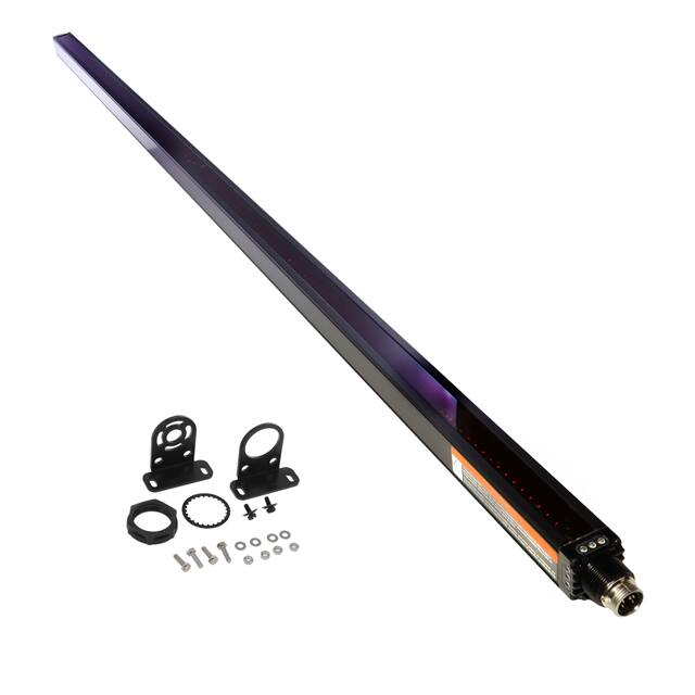
1.1 MINI-ARRAY Models
Each A-GAGE MINI-ARRAY system must include one controller and an emitter/receiver pair of matching length and
resolution. Configure and monitor the system using the supplied software and a user-supplied PC-compatible computer.
These MAC series controllers operate on 16 to 30 V dc and have one sensor pair input
and one gate input.
MAC Series Controllers
Models
Output 1
Output 2
MAC-1
Discrete Reed
Relay
Discrete NPN
MACN-1
Discrete NPN
MACP-1
Discrete PNP
MACV-1
Two Analog (0 to
10V dc Sourcing)
MACI-1
Two Analog (4 to
20 mA Sinking)
Serial
Output
Scan Analysis
Modes
PSF
Parameter
Part Number
8
43989
10
59114
RS-232
and
RS-485
Discrete PNP
Discrete NPN
RS-232
MAC16N-1
16 Discrete NPN Outputs
MAC16P-1
16 Discrete PNP Outputs
The dimensions for the MAC series controllers listed are: 110 × 100 × 75 mm (4.3 in ×
3.9 in × 3 in).
4
www.bannerengineering.com - Tel: + 1 888 373 6767
�A-GAGE® MINI-ARRAY® Measuring Light Screen System
Emitter/Receiver Pairs -- 19.1 mm (3/4 inch) Beam Spacing (16 beams/foot)
Emitter
Receiver
Array Length
Total Beams
BMEL616A
BMRL616A
133 mm (5.25 inch)
8
BMEL1216A
BMRL1216A
286 mm (11.25 inch)
16
BMEL1816A
BMRL1816A
438 mm (17.25 inch)
24
BMEL2416A
BMRL2416A
591 mm (23.25 inch)
32
BMEL3016A
BMRL3016A
743 mm (29.25 inch)
40
BMEL3616A
BMRL3616A
895 mm (35.25 inch)
48
BMEL4216A
BMRL4216A
1048 mm (41.25 inch)
56
BMEL4816A
BMRL4816A
1200 mm (47.25 inch)
64
BMEL6016A
BMRL6016A
1505 mm (59.25 inch)
80
BMEL7216A
BMRL7216A
1810 mm (71.25 inch)
96
Emitter/Receiver Pairs -- 9.5 mm (3/8 inch) Beam Spacing (32 beams/foot)
Emitter
Receiver
Array Length
Total Beams
BMEL632A
BMRL632A
143 mm (5.62 inch)
16
BMEL1232A
BMRL1232A
295 mm (11.62 inch)
32
BMEL1832A
BMRL1832A
448 mm (17.62 inch)
48
BMEL2432A
BMRL2432A
600 mm (23.62 inch)
64
BMEL3032A
BMRL3032A
752 mm (29.62 inch)
80
BMEL3632A
BMRL3632A
905 mm (35.62 inch)
96
BMEL4232A
BMRL4232A
1057 mm (41.62 inch)
112
BMEL4832A
BMRL4832A
1210 mm (47.62 inch)
128
BMEL6032A
BMRL6032A
1514 mm (59.62 inch)
160
BMEL7232A
BMRL7232A
1819 mm (71.62 inch)
192
Controller-to-Sensor Cables (two required per system)
Model
Length
QDC-515C
4.6 m (15 ft)
QDC-525C
7.6 m (25 ft)
QDC-550C
15.2 m (50 ft)
MAQDC-575C
22.7 m (75 ft)
MAQDC-5100C
30.3 m (100 ft)
MAQDC-5125C
37.9 m (125 ft)
MAQDC-5150C
45.5 m (150 ft)
www.bannerengineering.com - Tel: + 1 888 373 6767
QD Connector
5-pin Mini-style straight
5
�A-GAGE® MINI-ARRAY® Measuring Light Screen System
2 Overview
The Banner A-GAGE® MINI-ARRAY measuring light screen is ideal for applications such as on-the-fly product sizing and
profiling, edge-guiding and center-guiding, loop tensioning control, hole detection, parts counting, die ejection verification,
and similar uses.
A typical MINI-ARRAY System consists of the following components:
• Controller module
• Emitter
• Receiver
• Two interconnecting cables
Sensors are available in array lengths from 6 inches to 4 feet (in 6 inch increments), plus 5 foot and 6 foot array models.
Sensors are available with either 9.5 mm (3/8 inch) or 19.1 mm (3/4 inch) beam spacing, which translates to either 32 or 16
beams per foot of array length. Sensors with 3/8-inch beam spacing have a sensing range of up to 6 m (20 ft). Sensors with
3/4-inch beam spacing have a sensing range of up to 17 m (55 ft); 5 ft and 6 ft arrays have shorter ranges.
Some typical MINI-ARRAY applications are:
6
Paint Booth Profiling
Box Profiling
Inspection Applications
Edge Guiding
www.bannerengineering.com - Tel: + 1 888 373 6767
�A-GAGE® MINI-ARRAY® Measuring Light Screen System
2.1 System Features
Built-in features simplify the operation of the A-GAGE MINI-ARRAY system. Programmable beam blanking accommodates
machine components or other fixtures that must remain in or move through the light screen. Blanking is set by using the
included configuration software. See ######## for more information.
Built-in diagnostic programming and easy-to-see indicators on the sensors and the control module make alignment and
troubleshooting easy. The emitter has a red LED that signals proper operation. The receiver has three bright LEDs: green
signals that the sensors are properly aligned; yellow signals marginal alignment; and red signals misalignment or a blocked
condition.
The control module has seven status indicators: five red LEDs signal when outputs are conducting, Alarm output
conducting, and gate signal received; a green LED signals that the sensors are properly aligned. DIAG 1, 2, and 3 LEDs
indicate system status. A key to the diagnostics codes is printed on the side of the control module for simplified
troubleshooting.
The MINI-ARRAY System provides a wide selection of sensing and output options, including: measurement (“scan
analysis”) modes and scanning methods that can determine the target object’s location, overall size, total height or total
width. Scanning may be continuous or controlled by a host process controller or a gate sensor. Some models (MAC1,
MACP, MACN) support RS-485, where up to 15 systems may be networked.
Emitter
Receiver
DIN-Rail-Mountable Control Module
Red Discrete
Output #1 LED
Red Alarm
(Discrete Output #2) LED
MINI-ARRAY
CONTROLLER
MAC-1
RS-232
15
OUT 1
DIAG 1
ALARM
DIAG 2
GATE
DIAG 3
ALIGN
14
13
12
11
10
9
8
T/R
30V + + 500mA
150mA RS485 10-30V DC Max
GATE
Max.
OUT 1
ALARM
7
6
5
4
2
1
T/R DRN COM +12V
WH BK
F1
BU BR
L2 L1
16-30V DC
1.2A Max.
5 Wires
RS-232
Red Gate LED
EMTR
Green Align LED
3
15
14
13
12
11
10
9
2 - TX
3 - RX
5 - COM
RCVR
8
7
6
5
4
POWER
3 2 1
Red
Operational
LED
Green Alignment LED
Red Blocked LED
Yellow Marginal
Alignment LED
RS-232 Port
Figure 1. A-GAGE MINI-ARRAY System Features
2.2 Sensing Response
Sensing response is a function of the number of beams interrogated (steps) per scan of the array. The time per step is 55 μs
(0.000055 seconds). As a result, dense arrays (for example with 3/8 inch beam spacing) yield the highest sensing resolution.
Arrays with wider (3/4 inch) beam spacing offer faster sensing response.
2.3 Supplied System Software
The supplied software program, used to configure each system control module, may be run on any PC running Windows®
XP, Vista, or 7. The menu-driven program walks the user through the many scanning and output options. After the desired
options are selected, the user can save the combination of selections in a Parameter Setup File (PSF), and store it in the
control module’s non-volatile memory. Any number of PSFs may be stored in the computer and recalled as needed.
www.bannerengineering.com - Tel: + 1 888 373 6767
7
�A-GAGE® MINI-ARRAY® Measuring Light Screen System
The software also provides alignment and diagnostics routines. An Alignment screen displays the individual status of each
beam in the light screen, as well as the total number of beams in the system, and totals of beams blocked, made, and
blanked. Built-in system diagnostics can be used to assess emitter and receiver hardware errors.
8
www.bannerengineering.com - Tel: + 1 888 373 6767
�A-GAGE® MINI-ARRAY® Measuring Light Screen System
3 Specifications
3.1 Specifications for the Emitter/Receiver Pairs
Range (9.5 mm Beam Spacing)
0.6 m to 6.1 m (2 ft to 20 ft) for sensors < 4 ft
0.6 m to 4.6 m (2 ft to 15 ft) for sensors > 4 ft
Maximum range is specified at the point where 3× excess gain remains.
Range (19.1 mm Beam Spacing)
0.9 m to 17 m (3 ft to 55 ft) for sensors < 4 ft
0.9 m to 14 m (3 ft to 45 ft)for sensors > 4 ft
Maximum range is specified at the point where 3× excess gain remains.
Minimum Object Sensitivity (9.5 mm Beam Spacing)
19.1 mm (0.75 in)
Interlaced Mode: 12.7 mm (0.5 in)
Assumes sensing is in middle one-third of scanning range.
Minimum Object Sensitivity (19.1 mm Beam Spacing)
38.1 mm (1.5 in)
Interlaced Mode: 25.4 mm (1 in)
Assumes sensing is in middle one-third of scanning range.
Supply Voltage and Current (Emitter)
0.10 amps at 12 V dc
Maximum current is for a 6 ft sensor.
Supply Voltage and Current (Receiver)
9.5 mm beams: 0.75 amps at 12 V dc maximum
19.1 mm beams: 0.50 amps at 12 V dc maximum
Maximum current is for a 6 ft sensor.
Status Indicators (Emitter)
Red LED lights for proper operation
Construction
Aluminum housing with black anodized finish; acrylic lens cover
Sensor Scan Time
55 microseconds per beam, plus 1 millisecond processing time per
scan
Assumes straight scan, continuous scan, and TBB mode
Environmental Rating
IEC IP65
Operating Conditions
–20 °C to +70 °C (–4 °F to +158 °F)
95% maximum relative humidity (non-condensing)
Status Indicators (Receiver)
Green: sensors aligned (> 3× excess gain)
Amber: marginal alignment (1×-3× excess gain)
Red: sensors misaligned or beam(s) blocked
Connections
Emitter and receiver connect to controller using two 5-conductor quickdisconnect cables (one each for emitter and receiver), ordered
separately.
Cables measure 8.1 mm (0.32 in ) dia., and are shielded and PVCjacketed; conductors are 20-gauge.
Use only Banner cables, which incorporate a "“twisted pair” for noise
immunity on RS-485 data communication lines.
Emitter and receiver cables may not exceed 250 ft each.
3.2 Dimensions for the Emitters and Receivers
With Mounting Bracket Flanges Out
With Mounting Bracket Flanges In
38.1 mm square
[1.5”]
L2
L3
L1
X
2.5 mm
[0.10”]
18.3 mm
[0.72”]
10.2 mm
[0.4”]
Housing Length
Emitter/Receiver Models
Distance Between Bracket Holes
L1
L2
L3
BMEL6..A / BMRL6..A
201 mm (7.9 in)
233.9 mm (9.21 in)
177 mm (6.97 in)
BMEL12..A / BMRL12..A
356 mm (14 in)
389.7 mm (15.35 in)
332.8 mm (13.1 in)
www.bannerengineering.com - Tel: + 1 888 373 6767
9
�A-GAGE® MINI-ARRAY® Measuring Light Screen System
Housing Length
Distance Between Bracket Holes
Emitter/Receiver Models
L1
L2
L3
BMEL18..A / BMRL18..A
505 mm (19.9 in)
538.7 mm (21.22 in)
481.8 mm (18.97 in)
BMEL24..A / BMRL24..A
659 mm (26 in)
693.2 mm (27.31 in)
636.3 mm (25.05 in)
BMEL30..A / BMRL30.A
810 mm (31.9 in)
843.5 mm (33.23 in)
786.6 mm (30.97 in)
BMEL36..A / BMRL36.A
963 mm (37.9 in)
997.4 mm (39.29 in)
940.5 mm (37 in)
BMEL42..A / BMRL42.A
1115 mm (43.9 in)
1148 mm (45.2 in)
1091 mm (43 in)
BMEL48..A / BMRL48.A
1267 mm (49.9 in)
1301 mm (51.2 in)
1244 mm (49 in)
BMEL60..A / BMRL60..A
1572 mm (61.9 in)
1606 mm (63.2 in)
1549 mm (61 in)
BMEL72..A / BMRL72..A
1877 mm (73.9 in)
1910 mm (75.2 in)
1853 mm (73 in)
Beam Spacing
X (Distance for First Optical Channel)
9.5 mm (3/8 in)
38.1 mm (1.5 in)
19.1 mm (3/4 in)
42.9 mm (1.69 in)
3.3 Specifications for the MAC Controllers
Supply Voltage and Current
16 to 30 V dc at 1.25 amps maximum (see current requirements for
sensors)
Controller alone (without sensors connected) requires 0.1 amp
Inputs
MINI-ARRAY sensor input (5 connections); emitter and receiver wire in
parallel to five terminals
GATE input: Optically-isolated, requires 10 to 30 V dc (7.5K input
impedance) for gate signal
Discrete Outputs (MAC-1)
Output 1 (OUT 1): Reed relay contact rated 125 V ac/dc max., 10 VA
max. resistive load (non-inductive)
Output 2 (ALARM): Open collector NPN transistor rated 30 V dc max.,
150 mA max, short-circuit protected (may be configured as a second
data analysis output, system alarm output, or scan trigger output for a
parallel array)
OFF-STATE Leakage Current: < 10 μA at 30 V dc
ON-STATE Saturation Voltage: