WORLD-BEAM QS18U Ultrasonic Sensors
Datasheet
Miniature ultrasonic sensors with TEACH-mode programming
•
•
•
•
•
•
•
•
•
•
Fast, easy-to-use TEACH-Mode programming; no potentiometer adjustments
Ultra-compact housing
One discrete output: NPN or PNP, depending on model
Two bi-colored status LEDs
Rugged encapsulated version for harsh environments
Choose 2 meter or 9 meter unterminated cable, 4-pin M12 or 4-pin M8 QD connectors (either integral
or with 150 mm pigtail)
Wide operating range of –20 °C to +60 °C (–4 °F to +140 °F)
Temperature compensation
Configurable for normally open or normally closed operation
Fast response time (15 milliseconds)
WARNING:
• Do not use this device for personnel protection
• Using this device for personnel protection could result in serious injury or death.
• This device does not include the self-checking redundant circuitry necessary to allow its use in personnel safety
applications. A device failure or malfunction can cause either an energized (on) or de-energized (off) output condition.
Models
Models
Sensing Range
QS18UNA
QS18UPA
QS18UNAE
TEACH Option
Cable
Integral push button or remote TEACH (IP67,
NEMA 6P)
50 mm to 500 mm (2 in to 20 in)
Remote TEACH (epoxy-encapsulated, IP68,
NEMA 6P)
QS18UPAE
Supply Voltage
Output
NPN
4-wire, 2 m (6.5 ft) cable
with shield
PNP
12 V DC to 30 V DC
NPN
PNP
Only standard 2 m (6.5 ft) cable models are listed. For 9 m (30 ft) shielded cable, add suffix “W/30” to the model number (e.g., QS18UNA W/30). A
model with a QD connector requires a mating cordset. For QD models:
• To order the 4-pin integral M12 QD model, add the suffix Q8 (for example, QS18UNAQ8).
• To order the 150 mm (6 in) cable with a 4-pin M12 QD model, add the suffix Q5 (for example, QS18UNAQ5).
• To order the 4-pin integral M8 QD model, add the suffix Q7 (for example, QS18UNAQ7).
• To order the 150 mm (6 in) cable with a 4-pin M8 QD model, add the suffix Q (for example, QS18UNAQ).
Principles of Operation
Ultrasonic sensors emit one or multiple pulses of ultrasonic energy, which travel through the air at the speed of sound. A portion of this energy
reflects off the target and travels back to the sensor. The sensor measures the total time required for the energy to reach the target and return to the
sensor. The distance to the object is then calculated using the following formula: D = ct ÷ 2
D = distance from the sensor to the target
c = speed of sound in air
t = transit time for the ultrasonic pulse
To improve accuracy, an ultrasonic sensor may average the results of several pulses before outputting a new value.
Temperature Effects
The speed of sound is dependent upon the composition, pressure and temperature of the gas in which it is traveling. For most ultrasonic
applications, the composition and pressure of the gas are relatively fixed, while the temperature may fluctuate.
In air, the speed of sound varies with temperature according to the following approximation:
In metric units:
Cm/s = 20 √273 + TC
Cm/s = speed of sound in meters per second
TC = temperature in °C
In English units:
Cft/s = 49 √460 + TF
Cft/s = speed of sound in feet per second
TF = temperature in °F
Temperature Compensation
Changes in air temperature affect the speed of sound, which in turn affects the distance reading measured by the sensor. An increase in air
temperature shifts both sensing window limits closer to the sensor. Conversely, a decrease in air temperature shifts both limits farther away from the
sensor. This shift is approximately 3.5% of the limit distance for a 20° C change in temperature.
Original Document
119287 Rev. K
28 July 2021
119287
�WORLD-BEAM QS18U Ultrasonic Sensors
The QS18U series ultrasonic sensors are temperature compensated This reduces the error due to temperature by about 90%. The sensor will
maintain its window limits to within 1.8% over the -20° to +60° C (−4° to +140° F) range.
Note:
•
•
•
Exposure to direct sunlight can affect the sensor’s ability to accurately compensate for changes in temperature.
If the sensor is measuring across a temperature gradient, the compensation will be less effective.
The temperature warmup drift upon power-up is less than 7% of the sensing distance. After 5 minutes, the apparent
switchpoint will be within 0.6% of the actual position. After 25 minutes, the sensing position will be stable.
Sensor Programming
Two TEACH methods may be used to program the sensor:
• Teach individual minimum and maximum limits, or
• Use Auto-Window feature to center a sensing window around the taught position
The sensor may be programmed either via its push button, or via a remote switch. Remote
programming also may be used to disable the push button, preventing unauthorized personnel
from adjusting the programming settings. To access this feature, connect the white wire of the
sensor to 0V dc, with a remote programming switch between the sensor and the voltage.
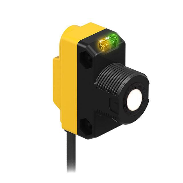
Figure 1. Sensor Features
Green/Red
Power/Signal
Strength LED
Yellow/Red
TEACH/Output
Indicator LED
Push Button
(IP67 models only)
Programming is accomplished by following the sequence of input pulses (see programming procedures). The duration of each pulse (corresponding
to a push button “click”), and the period between multiple pulses, are defined as “T: 0.04 seconds < T < 0.8 seconds."
Figure 2. TEACH Interface
Maximum
Operating
Range
Target
Far
Setpoint
Target
Target
Near
Setpoint
Target
Dead Zone
Minimum
Operating
Range
Power Output
Power
Output
Power Output
ON:
Green
ON:
Green
ON:
Yellow
ON:
Green
OFF
OFF
Power Output
ON:
Red
OFF
Status Indicators
Power ON/OFF LED
Indicates
Output/Teach LED
Indicates
OFF
Power is OFF
OFF
Target is outside window limits (normally open operation).
ON Red
Target is weak or outside sensing range.
Yellow
Target is within window limits (normally open operaton).
ON Green
Sensor is operating normally, good target.
ON Red (solid)
In Teach Mode, waiting for first limit.
ON Red (flashing)
In Teach Mode, waiting for second limit.
Teaching Minimum and Maximum Limits
General Notes on Programming
• The sensor returns to Run mode if the first TEACH condition is not registered within 120 seconds.
• After the first limit is taught, the sensor remains in Program mode until the TEACH sequence is finished.
• To exit Program mode without saving any changes, press and hold the programming push button for more than 2 seconds (before teaching
the second limit). The sensor reverts to the last saved limits.
2
www.bannerengineering.com - Tel: + 1 888 373 6767
P/N 119287 Rev. K
�WORLD-BEAM QS18U Ultrasonic Sensors
Figure 3. Teaching independent minimum and maximum limits
Normally Open Operation
Minimum
Limit
Output OFF
Maximum
Limit
Output ON
Output OFF
Normally Closed Operation
Minimum
Limit
Output ON
Maximum
Limit
Output OFF
Output ON
Procedure
Result
Push Button (0.04 sec ≤ Click ≤ 0.8 sec)
Remote Line (0.04 sec < T < 0.8 sec)
Programming Mode Press and hold push button
Teach First Limit
No action required; sensor is ready for 1st limit teach Output LED: ON Red
Power LED: ON Green (good signal) or ON Red (no
signal)
Position the target for the first limit
Position the target for the first limit
Power LED: Must be ON Green
Click the push button
Single-pulse the remote line
Teach Accepted
Output LED: Flashing Red
T
Teach Unacceptable
Output LED: ON Red
Teach Second Limit Position the target for the second limit
Click the push button
Position the target for the second limit
Power LED: Must be ON Green
Single-pulse the remote line
Teach Accepted
Output LED: Yellow or OFF
T
Teach Unacceptable
Output LED: Flashing Red
Teaching Limits Using the Auto-Window Feature
Teaching the same limit twice automatically centers a 20 mm window on the taught position.
General Notes on Programming
• The sensor returns to Run mode if the first TEACH condition is not registered within 120 seconds.
• After the first limit is taught, the sensor remains in Program mode until the TEACH sequence is finished.
• To exit Program mode without saving any changes, press and hold the programming push button for more than 2 seconds (before teaching
the second limit). The sensor reverts to the last saved program.
Figure 4. Using the Auto-Window feature for programming each output
Normally Open Operation
Taught Position
Position
- 10 mm
Output OFF
Position
+ 10 mm
Output ON
Output OFF
Normally Closed Operation
Taught Position
Position
- 10 mm
Output ON
P/N 119287 Rev. K
Position
+ 10 mm
Output OFF
Output ON
www.bannerengineering.com - Tel: + 1 888 373 6767
3
�WORLD-BEAM QS18U Ultrasonic Sensors
Procedure
Result
Push Button (0.04 sec ≤ Click ≤ 0.8 sec)
Programming
Mode
Teach First
Limit
Remote Line (0.04 sec < T < 0.8 sec)
Press and hold push button
No action required; sensor is ready for 1st limit Output LED: ON Red
teach
Power LED: ON Green (good signal) or ON Red
(no signal)
Position the target for the first limit
Position the target for the center of the window Power LED: Must be ON Green
Click the push button
Single-pulse the remote line
Teach Accepted
Output LED: Flashing Red
T
Teach Unacceptable
Output LED: ON Red
Re-Teach Limit Without moving the target, click the push
button again
Without moving the target, single-pulse the
remote line again
Teach Accepted
Output LED: Yellow or OFF
Teach Unacceptable
Output LED: Flashing Red
T
Figure 5. An application for the Auto-Window feature (retroreflective mode)
Taught Position
(background surface)
Near
Range
Position
-10 mm
Sensor
Output
ON
Position
+10 mm
Any object in this area will switch
the output, whether or not the object
returns a good signal to the sensor.
Sensor
Output
OFF
Output OFF
Output ON
Sensing Distance
Normally Open/Normally Closed Operation Select
Configure the sensor for either normally open or normally closed operation using the remote teach wire (white). A series of three pulses on the line
toggles between normally open (NO) and normally closed (NC) operation. Normally open is defined as the output energizing when the target is
present. Normally closed is defined as the output energizing when the target is absent. (See Teaching Minimum and Maximum Limits on p. 2 and
Teaching Limits Using the Auto-Window Feature on p. 3.)
Result
Procedure
Push Button (0.04 sec ≤ Click ≤ 0.8 sec)
Toggle between Not available via push button
NO/NC Operation
Remote Line (0.04 sec < T < 0.8 sec)
Triple-pulse the remote line
T
T
T
Selects either Normally Open or Normally
Closed operation depending on the
previous condition.
T
T
Push Button Lockout
Enables or disables the push button to prevent unauthorized personnel from adjusting the program settings.
Procedure
Push Button ( 0.04 sec ≤ Click ≤ 0.8 sec)
Push Button
Lockout
Not available via push button
Result
Remote Line ( 0.04 sec < T < 0.8 sec)
Four-pulse the remote line
T
T
T
4
T
T
T
Push buttons are either enabled or disabled,
depending on condition.
T
www.bannerengineering.com - Tel: + 1 888 373 6767
P/N 119287 Rev. K
�WORLD-BEAM QS18U Ultrasonic Sensors
Wiring Diagrams
Banner recommends connecting the shield wire to earth ground. Shielded cordsets are recommended for all QD models. Cabled wiring diagrams are
shown. Quick disconnect wiring diagrams are functionally identical.
Figure 6. NPN (Sinking) Output Models
Figure 7. PNP (Sourcing) Output Models
bn
bn
12 - 30V dc
bu
bk
wh
shield
12 - 30V dc
bu
bk
Load
wh
shield
Remote programming
switch (normally open)
Load
Remote programming
switch (normally open)
Specifications
Sensing Range
50 to 500 mm (2 to 20 inches)
Supply Voltage
12 V DC to 30 V DC (10% maximum ripple); 25 mA max (exclusive of load)
Ultrasonic Frequency
300 kHz, rep. rate 7.5 ms
Supply Protection Circuitry
Protected against reverse polarity and transient voltages
Repeatability
0.7 mm
Minimum Window Size
5 mm
Hysteresis
1.4 mm
Adjustments
Sensing Window Limits: TEH-mode programming of near and far window limits may
be set using the push button or remotely via TEH input
Output Configuration
SPST solid-state switch conducts when target is sensed within sensing window; one
NPN (current sinking) or one PNP (current sourcing), depending on model.
Output Protection
Protected against short-circuit conditions
Output Rating
Rating: 100 mA maximum load; see Application Note 1
Off-state leakage current: less than 10 µA (sourcing); less than 200 µA (sinking); see
Application Note 2
ON-state saturation voltage: NPN: less than 1.6 V at 100 mA; PNP: less than 3.0 V at
100 mA
Output Response
15 milliseconds
Delay at Power Up
300 milliseconds
Indicators
Range Indicator (Red/Green) and Teh/Output Indicator (Amber/Red)
Range Indicator: Green - Target is within sensing range; Red - Target is outside
sensing range; OFF - Sensing Power is OFF
Teh/Output Indicator: Amber - Target is within taught limits; OFF - Target is outside
taught window limits; Red - Sensor is in TEH mode
Construction
ABS housing, TPE Push Button, ABS Push Button housing, Polycarbonate lightpipes
Connections
2 m (6.5 ft) or 9 m (30 ft) 4-conductor PVC jketed atthed cable, or 4-pin Euro-style
integral QD (Q8), or 4-pin Pico-style integral QD (Q7), or 4-pin Euro-style 150 mm (6 in)
pigtail QD (Q5), or 4-pin Pico-style 150 mm (6 in) pigtail QD (Q)
Temperature Warmup Drift
See Temperature Compensation on p. 1
Temperature Effect
Non-encapsulated models: ± 0.05% per °C from –20 to 50 °C, ± 0.1% per °C from 50
to 60 °C
Encapsulated models: ± 0.05% per °C from 0 to 60 °C, ± 0.1% per °C from –20 to
0 °C
Application Notes
If supply voltage is > 24 V DC, derate maximum output current 5 mA/°C above 50 °C.
NPN off-state leakage current is < 200 µA for load resistances > 3 kΩ or optically
isolated loads. For load current of 100 mA, leakage is < 1% of load current.
Objects passing inside the specified near limit may produce a false response.
Environmental Rating
Leakproof design, rated NEMA 6P; IEC IP67 or IP68 depending on model; UL Type 1
Operating Conditions
−20 °C to 60 °C (−4 °F to 140 °F)
100% relative humidity (non-condensing)
Vibration and Mechanical Shock
All models meet MIL-STD-202F, Method 201A (Vibration: 10 Hz to 60 Hz maximum,
0.06 inch (1.52 mm) double amplitude, 10G maximum acceleration) requirements. Also
meets IEC 60947-5-2 (Shock: 30G 11 ms duration, half sine wave) requirements.
Certifications
Required Overcurrent Protection
P/N 119287 Rev. K
WARNING: Electrical connections must be made by
qualified personnel in accordance with local and
national electrical codes and regulations.
Overcurrent protection is required to be provided by end product application per the
supplied table.
Overcurrent protection may be provided with external fusing or via Current Limiting,
Class 2 Power Supply.
Supply wiring leads < 24 AWG shall not be spliced.
For additional product support, go to www.bannerengineering.com.
Supply Wiring (AWG)
Required Overcurrent Protection (Amps)
20
5.0
22
3.0
24
2.0
26
1.0
28
0.8
30
0.5
www.bannerengineering.com - Tel: + 1 888 373 6767
5
�WORLD-BEAM QS18U Ultrasonic Sensors
Figure 9. QS18U Maximum Target Rotation Angle
Figure 8. QS18U Effective Beam Pattern (Typical)
15°
50
Lateral Distance (mm)
40
10°
Target Rotation
30
20
10
0
-10
-20
5°
0
-5°
-10°
-30
-15°
-40
0
-50
0
100
200
300
400
Sensing Distance (mm)
100
200
500
300
400
500
Sensing Distance (mm)
2.5 mm rod
8 mm rod
50 mm x 50 mm plate
Dimensions
All measurements are listed in millimeters, unless noted otherwise.
Figure 10. Cabled models
Figure 11. M8 QD models
Figure 12. M12 QD models
41.5 mm
(1.63")
49 mm
(1.93")
33.5 mm
(1.32")
15.0 mm
(0.59")
17.1 mm
(0.67")
3 mm
(0.12")
24.1 mm
(0.95")
35.0 mm
(1.38")
M18 x 1 Thread
Max. Torque 2.3 Nm (20 in-lbs)
ø 3.3 mm (0.13")
Max. Torque 0.6 Nm (5 in-lbs)
Figure 13. Locknut (included with all models)
Figure 14. Washer (included with all models)
Ø 23.9 mm
(0.94")
24.2 mm
(0.95")
150 mm (6")
Euro-Style
Pigtail
Integral
4-pin
Pico-Style QD
150 mm (6")
Pico-Style
Pigtail
Integral
4-pin
Euro-Style QD
M3 Hardware Packet Contents
• 2 – M3 x 0.5 x 20 mm SS Screw
• 2 – M3 x 0.5 SS Hex Nut
1.6 mm
• 2 – M3 SS Washer
(0.06")
Ø 17.8 mm
(0.70")
8.0 mm
(0.32")
Accessories
Quick-Disconnect (QD) Cordsets
4-Pin Snap-On M8 Cordsets with Shield—Single Ended
Model
Length
Style
Dimensions
ø10 mm max.
(0.4")
PKG4S-2
2 m (6.56 ft)
Straight
28 mm max.
(1.1")
6
www.bannerengineering.com - Tel: + 1 888 373 6767
Pinout (Female)
4
3
2
1
1 = Brown
2 = White
3 = Blue
4 = Black
P/N 119287 Rev. K
�WORLD-BEAM QS18U Ultrasonic Sensors
4-Pin Snap-On M8 Cordsets with Shield—Single Ended
Model
Length
Style
Dimensions
Pinout (Female)
25 mm max.
(1.0")
4
1
3
PKW4ZS-2
2 m (6.56 ft)
2
20 mm
(0.8")
Right Angle
ø12 mm max.
(0.5")
4-Pin Threaded M12 Cordsets with Shield—Single Ended
Model
Length
MQDEC2-406
2 m (6.56 ft)
MQDEC2-415
5 m (16.4 ft)
Style
Dimensions
Pinout (Female)
44 Typ.
1
Straight
MQDEC2-430
9 m (29.5 ft)
MQDEC2-406RA
2 m (6.56 ft)
MQDEC2-415RA
5 m (16.4 ft)
M12 x 1
ø 14.5
2
30 Typ.
[1.18"]
Right-Angle
MQDEC2-430RA
3
4
32 Typ.
[1.26"]
2
1
1 = Brown
2 = White
3 = Blue
4 = Black
3
4
9 m (29.5 ft)
M12 x 1
ø 14.5 [0.57"]
Mounting Brackets
All measurements are listed in millimeters, unless noted otherwise.
SMB18A
• Right-angle mounting bracket
with a curved slot for versatile
orientation
• 12-ga. stainless steel
• 18 mm sensor mounting hole
• Clearance for M4 (#8) hardware
SMBQS18RA
• Right-angle mounting bracket
• 14-ga. 304 stainless steel
30
C
A
41
A
42
B
B
17
46
32
Hole center spacing: A to B = 24.2
Hole size: A = ø 4.6, B = 17.0 × 4.6, C = ø 18.5
Hole center spacing: A to B=20.3
Hole size: A =4.3 × 9.3, B=ø 4.3
SMB18SF
• 18 mm swivel bracket with M18 × 1
internal thread
• Black thermoplastic polyester
• Stainless steel swivel locking
hardware included
51
B
42
SMB18UR
• 2-piece universal swivel bracket
• 300 series stainless steel
• Stainless steel swivel locking
hardware included
• Mounting hole for 18 mm sensor
C
A
137
B
25
A
64
Hole center spacing: A = 36.0
Hole size: A = ø 5.3, B = ø 18.0
42
Hole center spacing: A = 25.4, B = 46.7
Hole size: B = 6.9 × 32.0, C = ø 18.3
P/N 119287 Rev. K
www.bannerengineering.com - Tel: + 1 888 373 6767
7
�WORLD-BEAM QS18U Ultrasonic Sensors
Banner Engineering Corp. Limited Warranty
Banner Engineering Corp. warrants its products to be free from defects in material and workmanship for one year following the date of shipment. Banner Engineering Corp. will repair or replace, free of charge,
any product of its manufacture which, at the time it is returned to the factory, is found to have been defective during the warranty period. This warranty does not cover damage or liability for misuse, abuse, or the
improper application or installation of the Banner product.
THIS LIMITED WARRANTY IS EXCLUSIVE AND IN LIEU OF ALL OTHER WARRANTIES WHETHER EXPRESS OR IMPLIED (INCLUDING, WITHOUT LIMITATION, ANY WARRANTY OF MERCHANTABILITY OR
FITNESS FOR A PARTICULAR PURPOSE), AND WHETHER ARISING UNDER COURSE OF PERFORMANCE, COURSE OF DEALING OR TRADE USAGE.
This Warranty is exclusive and limited to repair or, at the discretion of Banner Engineering Corp., replacement. IN NO EVENT SHALL BANNER ENGINEERING CORP. BE LIABLE TO BUYER OR ANY OTHER
PERSON OR ENTITY FOR ANY EXTRA COSTS, EXPENSES, LOSSES, LOSS OF PROFITS, OR ANY INCIDENTAL, CONSEQUENTIAL OR SPECIAL DAMAGES RESULTING FROM ANY PRODUCT DEFECT OR
FROM THE USE OR INABILITY TO USE THE PRODUCT, WHETHER ARISING IN CONTRACT OR WARRANTY, STATUTE, TORT, STRICT LIABILITY, NEGLIGENCE, OR OTHERWISE.
Banner Engineering Corp. reserves the right to change, modify or improve the design of the product without assuming any obligations or liabilities relating to any product previously manufactured by Banner
Engineering Corp. Any misuse, abuse, or improper application or installation of this product or use of the product for personal protection applications when the product is identified as not intended for such
purposes will void the product warranty. Any modifications to this product without prior express approval by Banner Engineering Corp will void the product warranties. All specifications published in this
document are subject to change; Banner reserves the right to modify product specifications or update documentation at any time. Specifications and product information in English supersede that which is
provided in any other language. For the most recent version of any documentation, refer to: www.bannerengineering.com.
For patent information, see www.bannerengineering.com/patents.
©
Banner Engineering Corp. All rights reserved
�