WORLD-BEAM® QS18E Series
Datasheet
•
•
•
•
•
•
•
•
•
Easy-to-use Expert-style Static and Dynamic TEACH options, plus Window, Light, and
Dark SET, via push button or remote input
Smart power-control algorithm to maximize performance in low-contrast applications
Easy push-button or remote sensor setup options:
◦ Dark-Operate/Light-Operate select
◦ Selectable 30 ms output OFF-delay
Less than 1 millisecond output response for excellent sensing repeatability
Tough ABS housing is rated IEC IP67; NEMA 6
Bright LED operating status indicators are visible from 360°
Discrete PNP or NPN output, depending on model
Multiple connection options available (see Models)
Compact housing, easy barrel-mount (some models) or side-mount installation
WARNING: Not To Be Used for Personnel Protection
Never use this device as a sensing device for personnel protection. Doing so could lead to serious injury or death. This device
does not include the self-checking redundant circuitry necessary to allow its use in personnel safety applications. A sensor
failure or malfunction can cause either an energized or de-energized sensor output condition.
Model
QS18EN6LP
QS18EP6LP
Sensing Mode
Range
660 nm Visible Red
3.5 m (12 ft) 1
P
Output
Model
NPN
QS18EN6CV15
PNP
QS18EP6CV15
QS18EN6D
800 mm (31.5 in)
QS18EN6DB
940 nm Infrared
QS18EP6DB
Range
Output
NPN
16 mm (0.65 in)
PNP
CONVERGENT
POLAR RETRO
QS18EP6D
Sensing Mode
660 nm Visible Red
500 mm (19.7 in)
NPN
QS18EN6CV45
PNP
QS18EP6CV45
NPN
QS18EN6FP
PNP
QS18EP6FP
43 mm (1.7 in)
NPN
PNP
NPN
660 nm Visible Red
Varies by mode and
fiber optics used
PNP
PLASTIC FIBER
QS18EN6W
QS18EP6W
DIFFUSE
300 mm (11.8 in)
NPN
QS18EN6DV
PNP
QS18EP6DV
NPN
660 nm Visible Red
600 mm (23.6 in)
PNP
DIFFUSE
The standard 2 m (6.5 ft) cable models are listed. To order the 9 m (30 ft) cable models, add the suffix "W/30" to the cabled model number. For example, QS18EN6FP W/30. Models with
a quick disconnect (QD) connector require a mating cable.
To order a model with a 4-pin QD 150 mm (6 in) Euro-style pigtail, add suffix “Q5” (for example, QS18EN6FPQ5).
To order a model with a 4-pin 150 mm (6 in) Pico-style pigtail, add suffix “Q” (for example, QS18EN6FPQ).
To order a model with a 4-pin Integral Euro-style QD, add suffix “Q8” (for example, QS18EN6FPQ8).
To order a model with a 4-pin Integral Pico-style QD, add suffix “Q7” (for example, QS18EN6FPQ7).
1 Specified using BRT-84 reflector (sold separately)
Original Document
136564 Rev. F
30 March 2020
136564
�WORLD-BEAM® QS18E Series
Overview of QS18E Expert Series Sensors
1
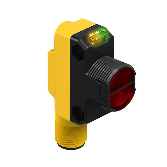
The QS18E Expert Sensors family of sensors provides high-performance sensing in a compact
package. The sensors feature a discrete output (NPN or PNP, depending on model), two bright
LEDs for easy status monitoring during configuration and operation, multiple configuration options,
remote configuration, and security lockout options.
1. Amber output LED
2. Green power indicator LED
3. Receiver port
4. Emitter port
5. Configuration button
2
3
4
Indicators (Two LEDs: One Green, One Amber)
Sensor Condition (Run Mode)
Green LED
Amber LED
Output OFF
ON
OFF
Output ON
ON
ON
Output ON, marginal signal
ON
Flashing
Output Short Circuit
Flashing
OFF
5
Figure 1. Sensor features
Wiring Diagrams
NPN (Sinking) Outputs
PNP (Sourcing) Outputs
10-30V dc
10-30V dc
Load
Load
Remote
Programming
(N.O.)
Remote
Programming
(N.O.)
Cabled wiring diagrams are shown. Quick disconnect (QD) wiring diagrams are functionally identical.
2
www.bannerengineering.com - Tel: + 1 888 373 6767
P/N 136564 Rev. F
�WORLD-BEAM® QS18E Series
Sensor Configuration
Configure the sensor using any of five TEACH or Set options (by push button or the remote wire) to
define the sensing limits. Use a Setup procedure to enable a 30 ms OFF-delay or to change the
Light-/Dark-Operate setting (see Sensor Setup on p. 3). Sensing limit configuration options
include:
• Static TEACH: one switching threshold, determined by two taught conditions
• Dynamic (on-the-fly) TEACH: one switching threshold, determined by multiple sampled
conditions
• Light Set and Dark Set: one switching threshold, offset from a single sensing condition (the
“dark” condition or the “light” condition; see Figure)
• Window Set: a sensing window, centered around a single sensing condition
The sensor’s output is disabled during all TEACH and Set procedures, and is enabled upon return to
Run mode.
Following any TEACH or Set procedure other than Static TEACH, the Output ON condition (Light- or
Dark-Operate setting) remains as it was last configured. To change that setting or the OFF-delay
setting, see Sensor Setup on p. 3.
Figure 2. Dark Sensing Condition
Remote Configuration
Use the remote function to configure the sensor remotely or to disable the push button for security. Connect the white wire of the sensor to ground
(0V dc), through a remote programming switch. Pulse the remote line according to the diagrams in the configuration procedures. The length of the
individual programming pulses is equal to the value T: 0.04 seconds ≤ T ≤ 0.8 seconds
Push Button Enable/Disable
The remote input may be used to disable the sensor push button to prevent unauthorized adjustment. Connect the white wire of the sensor as
described above to perform the procedure below to either enable or disable the feature.
Push Button Enable/Disable
Push Button ( 0.04 seconds ≤ "Click"
≤ 0.8 seconds)
Not available
Remote Line ( 0.04 seconds ≤ T ≤ 0.8 seconds)
Result
Sensor toggles between enable/disable settings and returns to RUN
mode.
From Run mode, four-pulse the remote line.
T
T
T
T
T
T
Power LED: Flashes 3x, then ON Green
Output LED: OFF,2 then ON or OFF, depending on output state
T
Returning to RUN Mode without Saving Settings
Exit Static TEACH and Set modes after the automatic 60-second time-out or by manually exiting the process. To manual exit, press and hold the
push button (or hold the remote line low) for 2 seconds. The sensor returns to Run mode without saving any new settings.
Sensor Setup
Access setup functions directly from Run mode using the following procedures.
30 ms OFF-Delay (Pulse Stretcher) Enable/Disable
Push Button (0.04 seconds ≤ “Click” ≤
0.8 seconds)
Remote Line (0.04 seconds ≤ T ≤ 0.8 seconds)
From Run mode, six-click the push button. From Run mode, six-pulse remote line.
T
T
T
T
T
T
T
T
T
T
T
Results
Sensor toggles between enable/disable settings and
returns to Run mode.
Power LED: Flashes 3x, then ON Green
Output LED: Enabled – ON, 3
Disabled – OFF, 3
Then ON or OFF, depending on output state
2 Initial output LED condition is simultaneous with Power LED 3-flash
3 Initial Output LED condition is simultaneous with Power LED 3-flash.
P/N 136564 Rev. F
www.bannerengineering.com - Tel: + 1 888 373 6767
3
�WORLD-BEAM® QS18E Series
Light-Operate/Dark-Operate Select
Push Button (0.04 seconds ≤ “Click” ≤
0.8 seconds)
Remote Line (0.04 seconds ≤ T ≤ 0.8 seconds)
From Run mode, seven-click the push
button.
From Run mode, seven-pulse remote line.
T
T
T
T
T
T
T
T
T
Results
T
T
Sensor toggles between Light-/Dark-Operate settings
and returns to Run mode.
Power LED: Flashes 3x, then ON Green
Output LED: Light Operate – ON, 3
Dark Operate – OFF, 3
T
T
Then ON or OFF, depending on output state
Static TEACH
2nd Taught
Condition
1st Taught
Condition
Sensor positions
threshold between
presented conditions
•
•
•
Output OFF
Output ON
Darkest
(no signal)
Static TEACH locates a single switching threshold (switchpoint)
at the optimal location between the two taught conditions, with
the Output ON condition on one side, and the Output OFF
condition on the other.
During Static TEACH, the first condition taught is the ON
condition. Output ON and OFF conditions may be reversed by
switching the TEACH order or by changing the Light-/DarkOperate setting in setup mode (see Sensor Setup on p. 3).
Static TEACH is recommended for applications where two
conditions can be presented individually.
Most Light
(saturated
signal)
Figure 3. Static TEACH (Light Operate shown)
1. Access the Static TEACH Mode.
Method
Action
Result
Push Button
Press and hold the push button 2 to 4 seconds.
Remote Line
No action required; the sensor is ready for the first sensing condition.
The sensor waits for the first sensing condition.
Power LED Indicator: OFF
Output LED Indicator: Slow flash (1Hz)
2. Teach the first sensing condition.
Method
Action
Result
Push Button
Present the first (ON) sensing condition, then click the
push button.
Remote Line
Present the first sensing condition, then single-pulse the
remote line.
T
Power LED Indicator: OFF
Output LED Indicator: Double-flash
3. Teach the second sensing condition.
Method
Push Button
Remote Line
Action
Result
Present the second (OFF) sensing condition, then click
the push button.
TEACH Accepted
Power LED Indicator: Flashes 3 times, then
solid green
Output LED Indicator: OFF
Present the second sensing condition, then single-pulse
the remote line.
T
The sensor returns to Run mode with the new
settings.
TEACH Not Accepted
Power LED Indicator: OFF
Output LED Indicator: Slow flash (1 Hz)
The sensor returns to the wait state, ready for
the first sensing condition.
4
www.bannerengineering.com - Tel: + 1 888 373 6767
P/N 136564 Rev. F
�WORLD-BEAM® QS18E Series
Dynamic TEACH
Darkest Presented
Condition
Lightest Presented
Condition
Sensor positions
threshold between
presented conditions
•
•
•
•
Output OFF
Output ON
Darkest
(no signal)
Dynamic TEACH sets a single switching threshold (switchpoint).
Dynamic TEACH is used to teach during actual sensing
conditions, taking multiple samples of the light and dark
conditions and automatically setting the threshold at the
optimum level.
The Output ON state (Light- or Dark-Operate setting) remains as
it was last configured. To change the Light-/Dark-Operate
setting, see Sensor Setup on p. 3.
Dynamic TEACH is recommended for applications where a
machine or process may not be stopped for teaching.
Most Light
(saturated
signal)
Figure 4. Dynamic TEACH (Light Operate shown)
1. Access the Dynamic TEACH mode.
Method
Action
Result
Push Button
Press and hold the push button for longer than 4
seconds.
Remote Line
Hold the remote line low (to ground) for longer than 2
seconds.
Power LED Indicator: OFF
Output LED Indicator: Quick flash (2 Hz)
2 seconds
2. Teach the sensing condition.
Method
Action
Result
Push Button
Continue to hold the push button and present the Output
ON and OFF conditions multiple times.
Remote Line
Continue to hold the remote line low (to ground) and
present the Output ON and OFF conditions multiple
times.
Power LED Indicator: OFF
Output LED Indicator: Quick flash (2 Hz)
3. Return to Run mode.
Method
Action
Push Button
Remote Line
Result
TEACH Accepted
Power LED Indicator: Flashes 3 times, then
solid green
Output LED Indicator: OFF4, then ON or OFF
depending on the output state
Release the push button.
The sensor returns to Run mode with the new
settings.
TEACH Not Accepted
Power LED Indicator: Flashes 3 times, then
solid green
Output LED Indicator: ON4, then ON or OFF
depending on the output state
Release the remote line/switch.
The sensor returns to Run mode without
changing settings.
Light Set
•
•
Sensor positions
threshold ≈12.5% below
the presented condition
Output OFF
Darkest
(no signal)
•
Output ON
Single
Presented
Condition
•
Light Set sets a threshold approximately 12.5% below the
presented sensing condition.
Any condition darker than the threshold causes the output to
change state.
In Light-Operate mode, the presented condition is the Output
ON condition. In Dark-Operate mode, the presented condition is
the Output OFF condition. To change the Light-/Dark-Operate
setting, see Sensor Setup on p. 3.
Light Set is recommended for applications where only one
condition is known, for example a stable light background with
varying darker targets, or in retroreflective applications.
Most Light
(saturated
signal)
Figure 5. Light Set (Light Operate shown)
4 The initial output LED indicator condition is simultaneous with the power LED indicator 3-flash
P/N 136564 Rev. F
www.bannerengineering.com - Tel: + 1 888 373 6767
5
�WORLD-BEAM® QS18E Series
1. Access the Light Set mode.
Method
Action
Result
Push Button
Press and hold the push button 2 to 4 seconds.
The sensor waits for the sensing condition.
Power LED Indicator: OFF
Output LED Indicator: Slow flash (1 Hz)
Remote Line
Single-pulse the remote line.
The sensor waits for the sensing condition.
Power LED Indicator: OFF
Output LED Indicator: Double-flash
T
2. Set the sensing condition.
Method
Push Button
Action
Result
TEACH Accepted
Power LED Indicator: Flashes 3 times, then
solid green
Output LED Indicator: OFF5, then ON or OFF,
depending on the output state
Present the sensing condition, then four-click the push
button.
Present the sensing condition, then four-pulse the remote line.
T
Remote Line
T
T
T
T
T
T
The sensor returns to Run mode with the new
settings.
TEACH Not Accepted
Power LED Indicator: OFF
Output LED Indicator: Slow flash (1 Hz)
The sensor returns to the wait state, ready for
the sensing condition.
Dark Set
•
•
Sensor positions
threshold ≈12.5% above
the presented condition
Output OFF
Darkest
(no signal)
Dark Set sets a threshold approximately 12.5% above the
presented sensing condition.
Any condition lighter than the threshold causes the output to
change state.
In Light-Operate mode, the presented condition is the Output
OFF condition. In Dark-Operate mode, the presented condition
is the Output ON condition. To change the Light-/Dark-Operate
setting, see Sensor Setup on p. 3.
Dark Set is recommended for applications where only one
condition is known, for example a stable dark background with
varying lighter targets, or when maximum excess gain is
required.
•
Output ON
Single
Presented
Condition
•
Most Light
(saturated
signal)
Figure 6. Dark Set (Light Operate shown)
1. Access the Dark Set mode.
Method
Action
Result
Push Button
Press and hold the push button 2 to 4 seconds.
The sensor waits for the sensing condition.
Power LED Indicator: OFF
Output LED Indicator: Slow flash (1 Hz)
Remote Line
Single-pulse the remote line.
The sensor waits for the sensing condition.
Power LED Indicator: OFF
Output LED Indicator: Double-flash
T
2. Set the sensing condition.
Method
Push Button
Action
Result
TEACH Accepted
Power LED Indicator: Flashes 3 times, then
solid green
Output LED Indicator: OFF6, then ON or OFF,
depending on the output state
Present the sensing condition, then five-click the push
button.
Present the sensing condition, then five-pulse the remote line.
Remote Line
T
T
T
T
T
T
T
T
T
The sensor returns to Run mode with the new
settings.
TEACH Not Accepted
Power LED Indicator: OFF
Output LED Indicator: Slow flash (1 Hz)
The sensor returns to the wait state, ready for
the sensing condition.
5 The initial output LED indicator condition is simultaneous with the power LED indicator 3-flash.
6 The initial output LED indicator condition is simultaneous with the power LED indicator 3-flash.
6
www.bannerengineering.com - Tel: + 1 888 373 6767
P/N 136564 Rev. F
�WORLD-BEAM® QS18E Series
Window Set
•
12.5%
Sensor positions
window thresholds
≈12.5% from the
presented condition
Output
ON
Output OFF
Darkest
(no signal)
•
•
Output OFF
Single
Presented
Condition
In Window Set, the single ON condition window extends
approximately 12.5% above and below the presented condition
when Light Operate is selected. Output ON and OFF conditions
may be reversed by changing the Light-/Dark-Operate setting
(see Sensor Setup on p. 3).
Lighter or darker conditions outside of the window cause the
output to change state.
Window Set is recommended for applications where the target
to be sensed may not always appear in the same place, or when
other unwanted signals may appear.
Most Light
(saturated
signal)
Figure 7. Window Set (Light Operate shown)
1. Access the Window Set mode.
Method
Action
Result
Push Button
Press and hold the push button 2 to 4 seconds.
The sensor waits for the sensing condition.
Power LED Indicator: OFF
Output LED Indicator: Slow flash (1 Hz)
Remote Line
Single-pulse the remote line.
The sensor waits for the sensing condition.
Power LED Indicator: OFF
Output LED Indicator: Double-flash
T
2. Set the sensing condition.
Method
Push Button
Remote Line
Action
Result
TEACH Accepted
Power LED Indicator: Flashes 3 times, then
solid green
Output LED Indicator: OFF7, then ON or OFF,
depending on the output state
Present the sensing condition, then double-click the
push button.
Present the sensing condition, then double-pulse the
remote line.
T
T
T
The sensor returns to Run mode with the new
settings.
TEACH Not Accepted
Power LED Indicator: OFF
Output LED Indicator: Slow flash (1 Hz)
The sensor returns to the wait state, ready for
the sensing condition.
Specifications
Supply Voltage
10 to 30 V dc (10% maximum ripple) at less than 35 mA, exclusive of load; 10 to 24 V
dc at > 55º C
Supply Protection Circuitry
Protected against reverse polarity and transient voltages
Output Configuration
Current sourcing (PNP) or current sinking (NPN), depending on model; Light- or darkoperate selectable; Selectable 30 ms output OFF-delay
Rating: 100 mA max
Off-state leakage current: less than 50 µA at 30 V dc (see Application Note 1)
ON-state saturation voltage: less than 1.5 V at 100 mA (1.7V for 30 ft cable models)
Output Protection Circuitry
Protected against false pulse on power-up and continuous overload or short-circuit of
output
Output Response
Note: Momentary delay on power-up; output does not conduct during this time
600 µs ON/OFF
Repeatability
75 µs
Construction
ABS housing, PMMA lens
Connections
PVC-jacketed 4-conductor 2 m (6.5 ft) or 9 m (30 ft) unterminated cable, or 4-pin Eurostyle or 4-pin Pico-style quick-disconnect (QD), either integral or 150 mm (6 in) pigtail,
are available. QD cordsets are ordered separately.
7 The initial output LED indicator condition is simultaneous with the power LED indicator 3-flash.
P/N 136564 Rev. F
www.bannerengineering.com - Tel: + 1 888 373 6767
7
�WORLD-BEAM® QS18E Series
Operating Conditions
Temperature: −20 °C to +70 °C (−4 °F to +158 °F)
Relative Humidity: 95% at +50 °C maximum relative humidity (non-condensing)
Application Notes
If the push button does not appear to be responsive, perform the push button enable
procedure
To maintain backwards compatibility with earlier models, 3 remote line pulses or a
push button hold followed by 3 push button clicks will perform a Dark SET.
Certifications
Required Overcurrent Protection
WARNING: Electrical connections must be made by
qualified personnel in accordance with local and
national electrical codes and regulations.
Overcurrent protection is required to be provided by end product application per the
supplied table.
Overcurrent protection may be provided with external fusing or via Current Limiting,
Class 2 Power Supply.
Supply wiring leads < 24 AWG shall not be spliced.
For additional product support, go to www.bannerengineering.com.
Supply Wiring (AWG)
Required Overcurrent Protection (Amps)
20
5.0
22
3.0
24
2.0
26
1.0
28
0.8
30
0.5
Dimensions
Model Suffix E, EV, R, FF
Model Suffix EB, RB
31.0 mm
(1.22")
17.1 mm
(0.67")
15.0 mm
(0.59")
Yellow
LED
Green
LED
3.0 mm
(0.12")
Model Suffix DB, W
21.1 mm
(0.82")
21.1 mm
(0.82")
3.0 mm
(0.12")
3.0 mm
(0.12")
Model Suffix FP
27.5 mm
(1.09")
15.0 mm
(0.59")
17.1 mm
(0.67")
7.5 mm
(0.30")
13.4 mm
(0.53")
24.1 mm
(0.95")
35.0 mm
(1.38")
5.2 mm
(0.21")
7.6 mm
(0.30")
Ø3.3 mm (0.13")
Max. torque 0.9 Nm (8 lbf. in)
A
Model Suffix F
Model Suffix CV15, CV45, D, DL, LV, LP
C
QS18...FP Fiber Installation
†
Single-turn
Sensitivity
Adjustment
†
31.0 mm
(1.22")
3.0 mm
(0.12")
CV Models:
33.2 mm (1.31")
17.1 mm
(0.67")
36.9 mm
(1.45")
M18x1 Thread
Max. torque 2.3 Nm (20 lbf. in)
A. Slide the fiber clip to open.
B. Insert fiber ends into each port,
as far as they will go.
C. Slide the fiber clip closed,
locking fibers into position.
19.8 mm
(0.78")
*Model Suffix Q
*Model Suffix Q5
*Model Suffix Q7
*Model Suffix Q8
(e.g. QS186EQ)
(e.g. QS186EQ5)
(e.g. QS186EQ7)
(e.g. QS186EQ8)
Slot for
Fiber Clip
M18 x 1 Jam Nut
Packing List
Sensor
M18 x 1 jam nut
M3 hardware packet
Installation sheet P/N 63687
24.2 mm(0.95")
8.0 mm(0.32")
B
41.5 mm
(1.63")
M3
2–
2–
2–
Hardware Packet Contents:
M3 x 0.5 x 20 mm SS screw
M3 x 0.5 SS hex nut
M3 SS washer
150 mm (6")
Pico-style
Pigtail
150 mm (6")
Euro-style
Pigtail
Integral
4-pin
Pico-Style QD
49 mm
(1.93")
Integral
4-pin
Euro-Style QD
All measurements are listed in millimeters [inches], unless noted otherwise.
Performance Curves
Performance using Dark Set, performed in no-light condition.
Polarized Retroreflective
Excess Gain
8
Beam Pattern
www.bannerengineering.com - Tel: + 1 888 373 6767
P/N 136564 Rev. F
�WORLD-BEAM® QS18E Series
Diffuse (Based on use of 90% reflectance white test card.)
Excess Gain
Beam Pattern
Excess Gain
Beam Pattern
Excess Gain
Beam Pattern
Excess Gain
Beam Pattern
Convergent
Excess Gain
Beam Pattern
Fiber Optic - Plastic
Excess Gain
Beam Pattern
Accessories
4-Pin Snap-on M8/Pico-Style Cordsets—Single Ended
Model
Length
Style
Dimensions
Pinout (Female)
4
32 Typ.
PKG4-2
2 m (6.56 ft)
2
1
3
Straight
ø 9.0
1 = Brown
2 = White
3 = Blue
4 = Black
P/N 136564 Rev. F
www.bannerengineering.com - Tel: + 1 888 373 6767
9
�WORLD-BEAM® QS18E Series
4-Pin Snap-on M8/Pico-Style Cordsets—Single Ended
Model
Length
Style
Dimensions
Pinout (Female)
29 Typ.
PKW4Z-2
2 m (6.56 ft)
Right-Angle
15 Typ.
ø 10.9
4-Pin Threaded M12/Euro-Style Cordsets—Single Ended
Model
Length
Style
MQDC-406
1.83 m (6 ft)
MQDC-415
4.57 m (15 ft)
MQDC-430
9.14 m (30 ft)
MQDC-450
15.2 m (50 ft)
MQDC-406RA
1.83 m (6 ft)
MQDC-415RA
4.57 m (15 ft)
MQDC-430RA
9.14 m (30 ft)
Dimensions
44 Typ.
Straight
M12 x 1
ø 14.5
2
1
3
4
32 Typ.
[1.26"]
30 Typ.
[1.18"]
Right-Angle
MQDC-450RA
Pinout (Female)
15.2 m (50 ft)
1 = Brown
2 = White
3 = Blue
4 = Black
M12 x 1
ø 14.5 [0.57"]
SMB312S
• Stainless steel 2-axis, sidemount bracket
SMBQS18DIN
• Right-angle bracket
assembly for mounting on 35
mm DIN rail
• 300 series stainless steel and
glass filled nylon; zinc-plated
screws
B
46
C
A
32
20
A = 4.3 × 7.5, B = diam. 3, C = 3 ×
15.3
SMBQS18Y
• Die-cast bracket for 18 mm
holes
• Includes metal hex nut and
lock washer
• Allows ± 8° for cabled
sensors
Hole size: A = ø 15.3
2x 8
3.4 mm
[0.13"]
4.5 mm
[0.18"]
2x R24.1 mm
[0.95"]
15.5 mm
[0.61"]
7.8 mm
[0.31"]
24.1 mm
[0.94"]
38.0 mm
[1.50"]
SMB18A
• Right-angle mounting bracket
with a curved slot for
versatile orientation
• 12-ga. stainless steel
• 18 mm sensor mounting hole
• Clearance for M4 (#8)
hardware
30
C
A
41
B
46
12.0 mm
[0.47"]
25.4 mm
[1"]
16.4 mm
[0.65"]
9.8 mm
[0.38"]
Hole center spacing: A to B = 24.2
Hole size: A = ø 4.6, B = 17.0 × 4.6, C = ø 18.5
19.5 mm
[0.77"]
14.5 mm
[0.57"]
10
www.bannerengineering.com - Tel: + 1 888 373 6767
P/N 136564 Rev. F
�WORLD-BEAM® QS18E Series
SMB3018SC
• 18 mm swivel side or barrelmount bracket
• Black reinforced
thermoplastic polyester
• Stainless steel swivel locking
hardware included
SMB4050YL
• Heavy-duty die-cast bracket
for industrial protection
• Replaceable window for use
with some sensor models
• M18 vertical mounting option
• Nut and lock washer included
67
B
59
29
A = ø 15.3
A
Hole center spacing: A = 50.8
Hole size: A = ø 7.0, B = ø 18.0
Additional available brackets: SMB46A, SMB18SF, SMBQS18RA, SMB18FA, SMBQS18A
For a list of reflectors or fiber optic assemblies, refer to the Accessories section of your current Banner Sensors catalog or visit
www.bannerengineering.com for complete information.
Banner Engineering Corp. Limited Warranty
Banner Engineering Corp. warrants its products to be free from defects in material and workmanship for one year following the date of shipment. Banner Engineering Corp. will repair or replace, free of charge,
any product of its manufacture which, at the time it is returned to the factory, is found to have been defective during the warranty period. This warranty does not cover damage or liability for misuse, abuse, or the
improper application or installation of the Banner product.
THIS LIMITED WARRANTY IS EXCLUSIVE AND IN LIEU OF ALL OTHER WARRANTIES WHETHER EXPRESS OR IMPLIED (INCLUDING, WITHOUT LIMITATION, ANY WARRANTY OF MERCHANTABILITY OR
FITNESS FOR A PARTICULAR PURPOSE), AND WHETHER ARISING UNDER COURSE OF PERFORMANCE, COURSE OF DEALING OR TRADE USAGE.
This Warranty is exclusive and limited to repair or, at the discretion of Banner Engineering Corp., replacement. IN NO EVENT SHALL BANNER ENGINEERING CORP. BE LIABLE TO BUYER OR ANY OTHER
PERSON OR ENTITY FOR ANY EXTRA COSTS, EXPENSES, LOSSES, LOSS OF PROFITS, OR ANY INCIDENTAL, CONSEQUENTIAL OR SPECIAL DAMAGES RESULTING FROM ANY PRODUCT DEFECT OR
FROM THE USE OR INABILITY TO USE THE PRODUCT, WHETHER ARISING IN CONTRACT OR WARRANTY, STATUTE, TORT, STRICT LIABILITY, NEGLIGENCE, OR OTHERWISE.
Banner Engineering Corp. reserves the right to change, modify or improve the design of the product without assuming any obligations or liabilities relating to any product previously manufactured by Banner
Engineering Corp. Any misuse, abuse, or improper application or installation of this product or use of the product for personal protection applications when the product is identified as not intended for such
purposes will void the product warranty. Any modifications to this product without prior express approval by Banner Engineering Corp will void the product warranties. All specifications published in this
document are subject to change; Banner reserves the right to modify product specifications or update documentation at any time. Specifications and product information in English supersede that which is
provided in any other language. For the most recent version of any documentation, refer to: www.bannerengineering.com.
For patent information, see www.bannerengineering.com/patents.
©
Banner Engineering Corp. All rights reserved
�