Q40 Sensors dc-Voltage Series
Datasheet
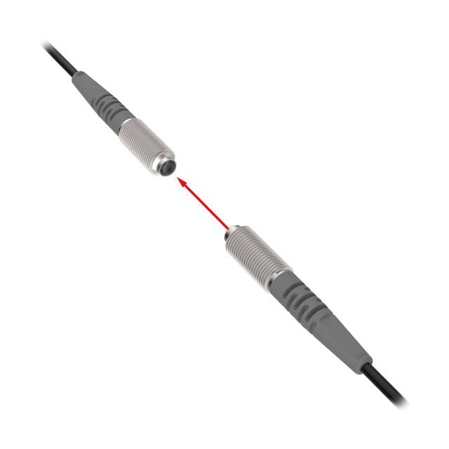
Self-contained, dc-operated sensors
WARNING: Not To Be Used for Personnel Protection
Never use this device as a sensing device for personnel
protection. Doing so could lead to serious injury or death.
This device does not include the self-checking redundant circuitry
necessary to allow its use in personnel safety applications. A
sensor failure or malfunction can cause either an energized or deenergized sensor output condition.
Models
Model1
Sensing Mode
Range
LED
Output
Infrared, 950 nm
NPN
Q406E
-
Q40SN6R
Opposed
OPPOSED
Q40SP6R
Q40SN6LP
Q40SP6LP
60 m (200 ft)
P
PNP
NPN
Polarized Retroreflective
6 m (20 ft)
Visible red, 680 nm
PNP
POLAR RETRO
Q40SN6FF200
Q40SN6FF400
Q40SP6FF400
NPN
200 mm (8 in) cutoff
Q40SP6FF200
Fixed Field
400 mm (16 in) cutoff
FIXED-FIELD
Q40SN6FF600
Q40SP6FF600
600 mm (24 in) cutoff
PNP
Infrared, 880 nm
NPN
PNP
NPN
PNP
Fixed-Field Mode Overview
Q40 Series self-contained fixed-field sensors are small, powerful, infrared diffuse mode sensors with far-limit cutoff. The
high excess gain of these sensors makes it possible for them to detect objects of low reflectivity. The fixed-field design
makes them ideal for detecting a part or surface that is directly in front of another surface, while ignoring the surface in
the background.
Installation
In the drawings and discussion in Excess Gain on page 4 and in Background Reflectivity and Placement on page 2,
the letters E, R1, and R2 identify how the sensor’s three optical elements (Emitter “E,” Near Detector “R1,” and Far
Detector “R2”) line up across the face of the sensor. In Figure 1 on page 2, Figure 2 on page 2, and Figure 3 on
page 2, these elements align vertically; in Figure 4 on page 2, they align horizontally. Note how the pattern on the
sensor’s lens helps to define the sensing axis of the sensor (Figure 6 on page 4). The sensing axis becomes important
in situations like those illustrated in Figure 3 on page 2 and Figure 4 on page 2.
1 Standard 2 m (6.5 ft) cable models are listed.
•
To order 9 m (30 ft) cable: add suffix "W/30" (for example, Q406E W/30).
•
To order 4-pin Euro-style QD models: add suffix "Q" (for example, Q406EQ). A model with a QD connector requires a mating cable.
Original Document
116167 Rev. B
14 November 2016
116167
�Q40 Sensors dc-Voltage Series
Background Reflectivity and Placement
Avoid mirror-like backgrounds that produce specular reflections. A false sensor response occurs if a background surface
reflects the sensor’s light more to the near detector (R1) than to the far detector (R2). The result is a false ON condition
(Figure 1 on page 2). To correct this problem, use a diffusely reflective (matte) background, or angle either the sensor
or the background (in any plane) so the background does not reflect light back to the sensor (see Figure 2 on page 2).
Position the background as far beyond the cutoff distance as possible.
An object beyond the cutoff distance, either stationary (and when positioned as shown in Figure 3 on page 2), or
moving past the face of the sensor in a direction perpendicular to the sensing axis, may cause unwanted triggering of the
sensor if more light is reflected to the near detector than to the far detector. The problem is easily remedied by rotating
the sensor 90° (Figure 4 on page 2) to align the sensing axis horizontally. The object then reflects the R1 and R2 fields
equally, resulting in no false triggering. A better solution, if possible, may be to reposition the object or the sensor.
Unwanted triggering of the sensor from an object beyond the cutoff can also be caused by attempting to sense a small
object that is moving perpendicular to the sensor face, or by an object moving through the off-center position shown in
Figure 3 on page 2. Making the object larger, centering the sensor relative to the object, or rotating the sensor to place
the sensing axis perpendicular to the longer dimension of the object (Figure 4 on page 2) will solve the problem.
Cutoff
Distance
Cutoff
Distance
Reflective
Background
R1 = Near Detector
R2 = Far Detector
E = Emitter
Cutoff
Reflective
Background
Fixed Sensing Field
Q40 sensor
Strong
Direct
Reflection
to R1
R1
R2
Core of
Emitted
Beam
E
Q40 sensor
R1
R2
E
Core of
Emitted
Beam
Strong Direct
Reflection
Away
From Sensor
Fixed Sensing Field
Figure 1. Reflective background - problem
R1 = Near Detector
R2 = Far Detector
E = Emitter
Figure 2. Reflective background - solution
Cutoff
Distance
Cutoff
Distance
Q40 sensor
Q40 sensor
R1
R2
E, R2, R1
E
Fixed
Sensing
Field
R1 = Near Detector
R2 = Far Detector
E = Emitter
E = Emitter
R2 = Far Detector
R1 = Near Detector
Reflective
Background
or
Moving Object
Fixed
Sensing
Field
Reflective
Background
or
Moving Object
Figure 4. Object beyond cutoff - solution
Figure 3. Object beyond cutoff - problem
Wiring Diagrams
Cabled Emitters
3
1
2
NPN (Sinking) Outputs
PNP (Sourcing) Outputs
Standard Hookup
Standard Hookup
3
–
10-30V dc
+
–
10-30V dc
+
1
4
2
Load
Load
www.bannerengineering.com - Tel: +1-763-544-3164
1
+
10-30V dc
–
3
4
2
Load
Load
P/N 116167 Rev. B
�Q40 Sensors dc-Voltage Series
Alarm Hookup
NOTE: QD
hookups are
functionally
identical.
1
2
3
–
10-30V dc
+
3
4
Alarm Hookup
+
10-30V dc
–
1
4
Load
2
Alarm
Load
Alarm
Specifications
Output Protection Circuitry
Protected against false pulse on power-up and continuous overload or
short circuit of outputs
Supply Voltage and Current
10 to 30 V dc (10% max. ripple)
Supply current (exclusive of load current):
Emitters: 25 mA
Receivers: 20 mA
Polarized Retroreflective: 30 mA
Fixed-Field: 35 mA
Output Response Time
Opposed mode: 3 ms ON, 1.5 ms OFF
Retro and Fixed-Field: 3 ms ON and OFF
NOTE: 100 ms delay on power-up; outputs
do not conduct during this time.
Supply Protection Circuitry
Protected against reverse polarity and transient voltages
Output Configuration
SPDT solid-state dc switch; Choose NPN (current sinking) or PNP
(current sourcing) models
Light Operate: N.O. output conducts when sensor sees its own (or the
emitter's) modulated light
Dark Operate: N.C. output conducts when the sensor sees dark; the
N.C. (normally closed) output may be wired as a normally open
marginal signal alarm output, depending upon hookup to power supply
(U.S. patent 5087838)
Output Rating
150 mA maximum (each) in standard hookup.
When wired for alarm output, the total load may not exceed 150 mA.
OFF-state leakage current: < 1 microamp at 30 V dc
ON-state saturation voltage: < 1V at 10 mA dc; < 1.5 V at 150 mA
dc
Required Overcurrent Protection
WARNING: Electrical connections must be
made by qualified personnel in accordance
with local and national electrical codes and
regulations.
Overcurrent protection is required to be provided by end product
application per the supplied table.
Overcurrent protection may be provided with external fusing or via
Current Limiting, Class 2 Power Supply.
Supply wiring leads < 24 AWG shall not be spliced.
For additional product support, go to www.bannerengineering.com.
Supply Wiring (AWG)
Required Overcurrent Protection (Amps)
20
5.0
22
3.0
24
2.0
26
1.0
28
0.8
30
0.5
P/N 116167 Rev. B
Repeatability
Opposed mode: 375 μs
Retro and Fixed-Field: 750 μs
Repeatability and response are independent of signal strength
Indicators
Two LEDs (Green and Amber)
Green ON steady: power to sensor is ON
Green flashing: output is overloaded
Amber ON steady: N.O. output is conducting
Amber flashing: excess gain marginal (1 to 1.5x) in light condition
Construction
PBT polyester housing; acrylic lens
Environmental Rating
Leakproof design rated NEMA 6P, IEC IP67. QD Models rated IEC IP69K
per DIN 40050-9.
Connections
2 m (6.5 ft) or 9 m (30 ft) attached cable, or 4-pin Euro-style quickdisconnect fitting
Operating Conditions
Temperature: −40 °C to +70 °C (−40 °F to +158 °F)
90% at +50 °C maximum relative humidity (non-condensing)
Vibration and Mechanical Shock
All models meet Mil. Std. 202F requirements. Method 201A (Vibration;
frequency 10 Hz to 60 Hz, max., double amplitude 0.06 inch
acceleration 10G). Method 213B conditions H&I. Shock: 75G with unit
operating; 100G for non-operation
Certifications
www.bannerengineering.com - Tel: +1-763-544-3164
3
�Q40 Sensors dc-Voltage Series
Dimensions
Cabled Models
40.1 mm
(1.58")
50.0 mm
(1.97")
QD Models
46.0 mm
(1.81")
Green LED
Power Indicator
Lens Centerline
50.0 mm
(1.97")
20.1 mm
(0.79")
19.8 mm
(0.78")
Yellow LED
Output Indicator
(Jam Nut Supplied)
19.8 mm
(0.78")
82.5 mm
(3.25")
M30 x 1.5 Thread
2 m (6.5') Cable
M30 x 1.5 Thread
(Jam Nut Supplied)
All measurements are listed in millimeters [inches], unless noted otherwise.
Excess Gain
The excess gain curves for these products are available on the
Banner website. They show excess gain versus sensing distance
for sensors with 200 mm, 400 mm, and 600 mm (8 in, 16 in, and
24 in) cutoffs. Maximum excess gain for all models occurs at a
lens-to-object distance of about 40 mm (1.57 in). Sensing at or
near this distance makes maximum use of each sensor’s available
sensing power.
Receiver
Elements
Near R1
Detector
Cutoff
Distance
Object B
or
Background
Object
A
Lenses
Far
R2
Detector
Backgrounds and background objects must always be placed
beyond the cutoff distance.
The excess gain curves were generated using a white test card of
90% reflectance. Objects with reflectivity of less than 90% reflect
less light back to the sensor, and thus require proportionately
more excess gain in order to be sensed with the same reliability
as more reflective objects. When sensing an object of very low
reflectivity, it may be especially important to sense it at or near
the distance of maximum excess gain.
Emitter
Sensing
Range
Object is sensed if amount of light at R1
is greater than the amount of light at R2
Figure 5. Fixed-field Concept
The effects of object reflectivity on cutoff distance, though small,
may be important for some applications. Sensing of objects of
less than 90% reflectivity causes the cutoff distances to be
“pulled” slightly closer to the sensor. For example, an excess gain
of 1 for an object that reflects 1/10 as much light as the 90%
white card is represented by the heavy horizontal graph line at
excess gain = 10. An object of this reflectivity results in far limit
cutoffs of approximately 190 mm, 250 mm, and 390 mm (7.48
in, 9.84 in, and 15.4 in) for the 200 mm, 400 mm, and 600 mm
(8 in, 16 in, and 24 in) cutoff models, respectively.
For highest sensitivity, the sensor-to-object distance should be
such that the object will be sensed at or near the point of
maximum excess gain. The background must be placed beyond
the cutoff distance. Following these two guidelines makes it
possible to detect objects of low reflectivity, even against close-in
reflective backgrounds.
4
E
R1
R2
Sensing
Axis
E
As a general rule, the most reliable sensing of an
object approaching from the side occurs when the
line of approach is parallel to the sensing axis.
Figure 6. Fixed-field sensing axis
www.bannerengineering.com - Tel: +1-763-544-3164
P/N 116167 Rev. B
�Q40 Sensors dc-Voltage Series
Quick-Disconnect (QD) Cables
4-Pin Threaded M12/Euro-Style Cordsets
Model
Length
MQDC-406
1.83 m (6 ft)
MQDC-415
4.57 m (15 ft)
MQDC-430
9.14 m (30 ft)
MQDC-450
15.2 m (50 ft)
MQDC-406RA
1.83 m (6 ft)
MQDC-415RA
4.57 m (15 ft)
MQDC-430RA
9.14 m (30 ft)
Style
Dimensions
44 Typ.
Straight
M12 x 1
ø 14.5
15.2 m (50 ft)
2
1
3
4
32 Typ.
[1.26"]
30 Typ.
[1.18"]
Right-Angle
MQDC-450RA
Pinout (Female)
1
2
3
4
=
=
=
=
Brown
White
Blue
Black
M12 x 1
ø 14.5 [0.57"]
Banner Engineering Corp. Limited Warranty
Banner Engineering Corp. warrants its products to be free from defects in material and workmanship for one year following the date of shipment. Banner Engineering Corp.
will repair or replace, free of charge, any product of its manufacture which, at the time it is returned to the factory, is found to have been defective during the warranty
period. This warranty does not cover damage or liability for misuse, abuse, or the improper application or installation of the Banner product.
THIS LIMITED WARRANTY IS EXCLUSIVE AND IN LIEU OF ALL OTHER WARRANTIES WHETHER EXPRESS OR IMPLIED (INCLUDING, WITHOUT LIMITATION,
ANY WARRANTY OF MERCHANTABILITY OR FITNESS FOR A PARTICULAR PURPOSE), AND WHETHER ARISING UNDER COURSE OF PERFORMANCE, COURSE
OF DEALING OR TRADE USAGE.
This Warranty is exclusive and limited to repair or, at the discretion of Banner Engineering Corp., replacement. IN NO EVENT SHALL BANNER ENGINEERING CORP. BE
LIABLE TO BUYER OR ANY OTHER PERSON OR ENTITY FOR ANY EXTRA COSTS, EXPENSES, LOSSES, LOSS OF PROFITS, OR ANY INCIDENTAL,
CONSEQUENTIAL OR SPECIAL DAMAGES RESULTING FROM ANY PRODUCT DEFECT OR FROM THE USE OR INABILITY TO USE THE PRODUCT, WHETHER
ARISING IN CONTRACT OR WARRANTY, STATUTE, TORT, STRICT LIABILITY, NEGLIGENCE, OR OTHERWISE.
Banner Engineering Corp. reserves the right to change, modify or improve the design of the product without assuming any obligations or liabilities relating to any product
previously manufactured by Banner Engineering Corp. Any misuse, abuse, or improper application or installation of this product or use of the product for personal protection
applications when the product is identified as not intended for such purposes will void the product warranty. Any modifications to this product without prior express approval
by Banner Engineering Corp will void the product warranties. All specifications published in this document are subject to change; Banner reserves the right to modify product
specifications or update documentation at any time. Specifications and product information in English supersede that which is provided in any other language. For the most
recent version of any documentation, refer to: www.bannerengineering.com.
©
Banner Engineering Corp. All rights reserved
�