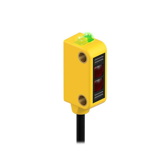
WORLD-BEAM® Q12 Series Sensor
Datasheet
Miniature self-contained photoelectric sensors in universal housing
•
•
•
•
•
•
•
•
•
•
Standard Model
Bright, visible red (640 nm) light source
Standard models available with 4-wire 2 m (6.5 ft) or 9 m (30 ft) cable or 3 or 4wire 150 mm (6 in) pigtail with Pico-style M8 threaded connector
Solid-state, bipolar outputs: one current sourcing (PNP) and one current sinking
(NPN) standard on 4-wire models
Single output solid-state PNP or NPN standard on Q3 models
Light Operate (LO) or Dark Operate (DO), depending on model
Models available with PFA chemical-resistant jacket (1200 psi washdown rated)
for use in harsh environments
Compact 8 mm (0.31 in) housing mounts almost anywhere
Crosstalk avoidance circuitry for applications with multiple sensors
LED status indicators for Power ON, Output Overload, Signal Received, and
Marginal Signal
Advanced ASIC technology makes sensor resistant to optical and electrical noise
source
Chemical-Resistant
Model
WARNING:
• Do not use this device for personnel protection
• Using this device for personnel protection could result in serious injury or death.
• This device does not include the self-checking redundant circuitry necessary to allow its use in
personnel safety applications. A device failure or malfunction can cause either an energized (on) or deenergized (off) output condition.
Chemical-Resistant Models
Model1
Sensing Mode
640 nm Visible Red
Range
Q126ECR
Output
N/A
Q12AB6RCR
Bipolar LO
1.5 m (4.9 ft)
OPPOSED
Q12RB6RCR
Bipolar DO
Effective Beam: 5.7 mm (0.22 in)
Performance based on use of 90% reflectance white test card.
Q12AB6FF15CR
Q12RB6FF15CR
Q12AB6FF30CR
FIXED-FIELD
VISIBLE RED
640 nm Visible Red
Q12RB6FF30CR
Q12AB6FF50CR
Q12RB6FF50CR
Bipolar LO
13 mm (0.5 in) cutoff;
8 mm (0.3 in) focus
Bipolar DO
28 mm (1.1 in) cutoff;
14 mm (0.6 in) focus
Bipolar DO
48 mm (1.9 in) cutoff;
14 mm (0.6 in) focus
Bipolar DO
Bipolar LO
Bipolar LO
1 Only standard 2 m (6.5 ft) cables are available for chemical-resistant models.
Original Document
119223 Rev. M
7 April 2020
119223
�WORLD-BEAM® Q12 Series Sensor
Standard Models
Model2
Sensing Mode
Q126E (emitter)
640 nm Visible Red
Q126EQ3 (emitter)
Range
2m
(6.5 ft)
Connection
Output
2 m (6.5 ft) cable
N/A
150 mm (6 in) cable with a 3-pin M8/
Pico-style QD
N/A
Q12AB6R
2 m (6.5 ft) cable
Q12RB6R
Q12AP6RQ3
OPPOSED
Effective Beam: 5.7 mm (0.22 in)
2m
(6.5 ft)
Q12RP6RQ3
Q12AN6RQ3
1 PNP LO
150 mm (6 in) cable with a 3-pin M8/
Pico-style QD
Q12RN6RQ3
Q12AB6LP
2 m (6.5 ft) cable
Q12AP6LPQ3
POLAR RETRO
640 nm Visible Red
Q12RP6LPQ3
150 mm (6 in) cable with a 3-pin M8/
Pico-style QD
Q12AN6LPQ3
Bipolar LO
Bipolar DO
1 PNP DO
1 NPN LO
1 NPN DO
Q12AB6LV
2 m (6.5 ft) cable
Q12RB6LV
Q12AP6LVQ3
640 nm Visible Red
1 NPN LO
1 PNP LO
1 m (40 in) 3
Q12RN6LPQ3
RETRO
1 PNP DO
1 NPN DO
Q12RB6LP
P
Bipolar LO
Bipolar DO
1.5 m
(59 in) 3
Q12RP6LVQ3
Q12AN6LVQ3
Bipolar LO
Bipolar DO
1 PNP LO
150 mm (6 in) cable with a 3-pin M8/
Pico-style QD
Q12RN6LVQ3
1 PNP DO
1 NPN LO
1 NPN DO
Performance based on use of 90% reflectance white test card.
Q12AB6FF15
Q12RB6FF15
Q12AP6FF15Q3
Q12RP6FF15Q3
Q12AN6FF15Q3
2 m (6.5 ft) cable
15 mm (0.6 in)
cutoff;
10 mm (0.4 in)
focus
1 PNP LO
150 mm (6 in) cable with a 3-pin M8/
Pico-style QD
Q12RN6FF15Q3
Q12AB6FF30
Q12AP6FF30Q3
640 nm Visible Red
Q12RP6FF30Q3
2 m (6.5 ft) cable
30 mm (1.2 in)
cutoff;
16 mm (0.63 in) focus
Q12AN6FF30Q3
150 mm (6 in) cable with a 3-pin M8/
Pico-style QD
2 m (6.5 ft) cable
Q12RB6FF50
Q12AN6FF50Q3
50 mm (2 in)
cutoff; 16 mm (0.63 in)
focus
1 PNP DO
1 NPN LO
Bipolar LO
Bipolar DO
1 PNP LO
150 mm (6 in) cable with a 3-pin M8/
Pico-style QD
Q12RN6FF50Q3
2
Bipolar LO
Bipolar DO
1 NPN DO
Q12AB6FF50
Q12RP6FF50Q3
1 NPN LO
1 PNP LO
Q12RN6FF30Q3
Q12AP6FF50Q3
1 PNP DO
1 NPN DO
Q12RB6FF30
FIXED-FIELD
VISIBLE RED
Bipolar LO
Bipolar DO
1 PNP DO
1 NPN LO
1 NPN DO
To order the 9 m (30 ft) cable model, add the suffix W/30 to the model number. For example, Q126E W/30.
To order the 150 mm (6 in) cable with a 4-pin M8/Pico-style (M8 threaded) QD model, add the suffix Q to the model number. For example,
Q126EQ.
•
To order the 150 mm (6 in) cable with a 4-pin M12/Euro-style QD model, add the suffix Q5 to the model number. For example Q126EQ5.
3 Retroreflective range is specified using one model BRT-60X40C retroreflector. Actual sensing range may be more or less than specified, depending upon
efficiency and reflective area of the retroreflector(s) used.
2
•
•
www.bannerengineering.com - Tel: + 1 888 373 6767
P/N 119223 Rev. M
�WORLD-BEAM® Q12 Series Sensor
Indicator Features
1 - Amber and green LEDs
• Green on: power to sensor is on
• Amber on: received signal
• Amber flashing: marginal signal
1
Chemical-Resistant models: LEDs are visible through translucent PFA jacket. Rated to 1200 psi
washdown.
Wiring
Emitters have no connection to black and white.
CAUTION: Observe proper ESD precautions (grounding) when connecting QD models.
Bipolar Models, Light Operate
Emitters
bn (1)
brown
wh (2)
10–30 V DC
blue
+
10–30 V dc
–
bu (3)
+
bk (4)
–
–
10–30 V dc
+
bn (1)
bk (4)
Load
PNP Models, Dark Operate
+
10–30 V dc
–
bn (1)
Load
bk (4)
NPN Models, Dark Operate
bu (3)
+
10–30 V dc
–
bu (3)
Load
–
10–30 V dc
+
bn (1)
bk (4)
Load
Load
Load
3-pin M8/Pico-style Male QD
1 = Brown
2 = White
3 = Blue
4 = Black
bu (3)
Load
bu (3)
Key
NPN Models, Light Operate
+
10–30 V dc
–
bu (3)
bk (4)
bn (1)
bk (4)
bn (1)
Load
Bipolar Models, Dark Operate
wh (2)
PNP Models, Light Operate
4
3
1
4-pin M8/Pico-style Male QD
2
4
1
3
4-pin M12/Euro-style Male QD
2
3
1
4
Specifications
Supply Voltage and Current
10 to 30 V dc (10% maximum ripple) at 20 mA maximum current
Sensing Beam
640 nm visible red
Supply Protection Circuitry
Protected against reverse polarity and transient voltages
P/N 119223 Rev. M
Output Configuration
Bipolar (1 NPN and 1 PNP) solid-state output or Single output (PNP or
NPN), LO or DO, depending on model
Repeatability
125 microseconds
Switching Frequency
Opposed Mode: 385 Hz
LP/LV Mode: 715 Hz
FF Mode: 590 Hz
www.bannerengineering.com - Tel: + 1 888 373 6767
3
�WORLD-BEAM® Q12 Series Sensor
Output Protection Circuitry
Protected against false pulse on power-up, short-circuit protected
Output Response Time
Opposed Mode: 1.3 ms ON; 900 µs OFF
LP/LV Mode: 700 µs ON/OFF
FF Mode: 850 µs ON/OFF
NOTE: 120 ms delay on power-up; outputs do not conduct during this time.
Indicators
One Yellow and one Green LED (see Figure 1)
Construction
Polarized Retro Models: Thermoplastic elastomer housing with glass lens
All Other Standard Models: Thermoplastic elastomer housing with
polycarbonate lens
Chemical-Resistant Models: Housing encased in PFA jacket; cable encased
in 3/16 in O.D. PFA tubing
Connections
Standard Models: 2 m (6.5 ft) or 9 m (30 ft) attached PVC cable, or 150 mm
(6 in) pigtail with M8 or M12 threaded connection, depending on the model
ordered
Chemical-Resistant Models: 2 m (6.5 ft) cable encased in 3/16 in O.D. PFA
tubing
Environmental Rating
Standard Models: IEC IP67
Chemical-Resistant Models: IEC IP67 (NEMA6) and PW12 1200 psi
washdown per NEMA ICS5, Annex F-2002
Output Ratings
OFF-state leakage current:
NPN: 10 µA
PNP: 10 µA
ON-state saturation voltage:
NPN: 2 V at 50 mA
PNP: 2 V at 50 mA
Vibration and Mechanical Shock
All models meet MIL-STD-202F, Method 201A (Vibration: 10 Hz to 60 Hz
maximum, 0.06 inch (1.52 mm) double amplitude, 10G maximum
acceleration) requirements. Also meets IEC 60947-5-2 (Shock: 30G 11 ms
duration, half sine wave) requirements.
Required Overcurrent Protection
WARNING: Electrical connections must be
made by qualified personnel in accordance with
local and national electrical codes and
regulations.
Overcurrent protection is required to be provided by end product
application per the supplied table.
Overcurrent protection may be provided with external fusing or via Current
Limiting, Class 2 Power Supply.
Supply wiring leads < 24 AWG shall not be spliced.
For additional product support, go to www.bannerengineering.com.
Conditions
Operating Temperature: –20 °C to +55 °C (–4 °F to +131°F)
Storage Temperature: –30 °C to +75 °C (–22 °F to +167 °F)
95% at +50 °C maximum relative humidity (non-condensing)
Supply Wiring (AWG)
Required Overcurrent Protection (Amps)
20
5.0
22
3.0
24
2.0
26
1.0
28
0.8
30
0.5
Certifications
(Chemical-resistant models are
not UR/UL approved.)
Dimensions
12.4 mm
(0.49")
M3 mounting
screws included
8.0 mm
(0.31")
15.0 mm
(0.59")
5.1 mm
(0.20")
23.1 mm
(0.91") 22 mm
(0.86")
3.5 mm
(0.14")
3.4 mm
(0.13")
Polarized Retro
Models
4.7 mm
(0.19")
Emitter (opposed mode models)
Emitter (all other models)
Ø 3 mm (0.12")
max. torque
0.9 Nm (8 in-lbf)
Figure 1. Standard Models
4
www.bannerengineering.com - Tel: + 1 888 373 6767
P/N 119223 Rev. M
�WORLD-BEAM® Q12 Series Sensor
22.6 mm
(0.89")
8.1 mm (0.32")
12.5 mm (0.49")
Mounting hardware
not included
5.9 mm (0.23")
3.2 mm (0.13")
Ø 3.4 mm (0.13")
max. torque*
0.9 Nm (8 in-lbf)
* When mounting by running a screw through
both flanges without support between the flanges,
the max. torque applied should be 0.1 Nm (1 in-lbf).
6.2 mm
(0.25")
Emitter (opposed mode models)
28.8 mm (1.13")
15.0 mm (0.59")
10.7 mm (0.42")
4.7 mm
(0.18")
8.6 mm (0.34")
5.5 mm (0.22")
Emitter (all other models)
4.8 mm (0.19") O.D.
PFA Tube
2 m (6.5')
Ø12.5 mm (0.49")
Figure 2. Chemical-Resistant Models
Performance Curves - Opposed Mode
Excess Gain
Beam Pattern
1000
Q12..
EXCESS GAIN
Opposed Mode
Q12..
30 mm
1.2"
Opposed Mode
20 mm
100
0.8"
10 mm
0.4"
0
Standard
0
Chemical-Resistant
10 mm
10
0.4"
20 mm
0.8"
30 mm
Standard
1.2"
Chemical-Resistant
1
0.01 m
0.033'
0
0.1 m
0.33'
1m
3.3'
0.5 m
20"
10 m
33'
1m
40"
1.5 m
60"
2m
80"
2.5 m
100"
DISTANCE
DISTANCE
Performance Curves - Retroreflective Mode
Performance is based on the use of a model BRT-60X40C retroreflector.
Polarized Retroreflective
Excess Gain
Retroreflective
Beam Pattern
Excess Gain
EXCESS GAIN
100
Q12..
Q12..
9 mm
Polarized Retro
6 mm
0.2"
3 mm
0.1"
0
0
3 mm
10
0.1"
6 mm
0.2"
9 mm
0.3"
0
0.1 m
0.33'
1m
3.3'
DISTANCE
P/N 119223 Rev. M
10 m
33'
0.3"
0.3 m
12"
0.6 m
24"
0.9 m
35"
DISTANCE
1.2 m
47"
1.5 m
59"
Retroreflective
EXCESS GAIN
Q12..
Polarized Retro
1
0.01 m
0.03'
Beam Pattern
1000
1000
Q12..
30 mm
100
Retroreflective
0.8"
10 mm
0.4"
0
0
10
10 mm
0.4"
20 mm
0.8"
30 mm
1
0.01 m
0.03'
1.2"
0
0.1 m
0.33'
1m
3.3'
10 m
33'
1.2"
20 mm
0.3 m
12"
0.6 m
24"
0.9 m
35"
1.2 m
47"
1.5 m
59"
DISTANCE
DISTANCE
www.bannerengineering.com - Tel: + 1 888 373 6767
5
�WORLD-BEAM® Q12 Series Sensor
Performance Curves - Fixed-Field
Focus and spot sizes are typical. Performance based on use of 90% reflectance white test card.*
Fixed Field -- 15 mm
Fixed Field -- 30 mm
Fixed Field -- 50 mm
1000
1000
1000
Standard
10
100
Standard
10
100
Standard
10
Chemical-Resistant
Chemical-Resistant
Chemical-Resistant
100 mm
4.0"
EXCESS GAIN
EXCESS GAIN
EXCESS GAIN
100
10 mm
0.4"
Fixed-Field Mode
Fixed-Field
Fixed-Field
1
1 mm
0.04"
Q12..FF50
Q12..FF30
Q12..FF15
1
1 mm
0.04"
1000 mm
40.0"
10 mm
0.4"
100 mm
4.0"
1
1 mm
0.04"
1000 mm
40.0"
100 mm
4.0"
1000 mm
40.0"
DISTANCE
DISTANCE
DISTANCE
Standard Models:
Standard Models:
10 mm
0.4"
Standard Models:
•
Ø 0.4 mm spot size at 10 mm focus
•
Ø 0.5 mm spot size at 16 mm focus
•
Ø 0.5 mm spot size at 16 mm focus
•
Ø 1.5 mm spot size at 15 mm cutoff
•
Ø 3.0 mm spot size at 30 mm cutoff
•
Ø 6.5 mm spot size at 50 mm cutoff
Chemical-Resistant Models:
•
Ø 0.4 mm spot size at 8 mm focus
•
Ø 1.5 mm spot size at 13 mm cutoff
Chemical-Resistant Models:
•
Ø 0.5 mm spot size at 14 mm focus
•
Ø 3.0 mm spot size at 28 mm cutoff
* Using 18% gray test card: cutoff distance will be
95% of value shown.
Using 6% black test card: cutoff distance will be
90% of value shown.
* Using 18% gray test card: cutoff distance will be
80% of value shown.
Using 6% black test card: cutoff distance will be
60% of value shown.
* Using 18% gray test card: cutoff distance will be
90% of value shown. Using 6% black test card:
cutoff distance will be 80% of value shown.
Chemical-Resistant Models:
•
Ø 0.5 mm spot size at 14 mm focus
•
Ø 6.5 mm spot size at 48 mm cutoff
* Using 18% gray test card: cutoff distance will be
70% of value shown. Using 6% black test card:
cutoff distance will be 50% of value shown.
Accessories
Cordsets
3-Pin Threaded M8/Pico-Style Cordsets
Model
Length
PKG3M-2
2.035 m (6.68 ft)
PKG3M-5
5.035 m (16.51 ft)
PKG3M-7
7.035 m (23.08 ft)
PKG3M-9
9.035 m (29.64 ft)
PKG3M-10
10.035 m (32.92 ft)
PKW3M-2
2 m (6.56 ft)
PKW3M-5
5 m (16.40 ft)
Style
Dimensions
35 Typ.
Straight
ø 9.5
M8 x 1
4
1
3
28 Typ.
20 Typ.
Right-Angle
PKW3M-9
Pinout (Female)
1 = Brown
3 = Blue
4 = Black
9 m (29.53 ft)
M8 x 1
ø 9.5
6
www.bannerengineering.com - Tel: + 1 888 373 6767
P/N 119223 Rev. M
�WORLD-BEAM® Q12 Series Sensor
4-Pin Threaded M8/Pico-Style Cordsets—Single Ended
Model
Length
PKG4M-2
2 m (6.56 ft)
PKG4M-5
5 m (16.4 ft)
Style
Dimensions
Pinout (Female)
35 Typ.
Straight
PKG4M-9
9 m (29.5 ft)
PKW4M-2
2 m (6.56 ft)
PKW4M-5
5 m (16.4 ft)
ø 9.5
2
1
3
28 Typ.
1 = Brown
2 = White
3 = Blue
4 = Black
20 Typ.
Right Angle
PKW4M-9
4
M8 x 1
9 m (29.5 ft)
M8 x 1
ø 9.5
4-Pin Threaded M12/Euro-Style Cordsets—Single Ended
Model
Length
MQDC-406
1.83 m (6 ft)
MQDC-415
4.57 m (15 ft)
MQDC-430
9.14 m (30 ft)
MQDC-450
15.2 m (50 ft)
MQDC-406RA
1.83 m (6 ft)
MQDC-415RA
4.57 m (15 ft)
MQDC-430RA
9.14 m (30 ft)
Style
Dimensions
44 Typ.
Straight
M12 x 1
ø 14.5
3
4
1 = Brown
2 = White
3 = Blue
4 = Black
30 Typ.
[1.18"]
15.2 m (50 ft)
2
1
32 Typ.
[1.26"]
Right-Angle
MQDC-450RA
Pinout (Female)
M12 x 1
ø 14.5 [0.57"]
Brackets
SMBQ12T
•
Right-angle bracket
20-ga. 300 series stainless
•
steel
SMBQ12A
•
Adjustable right-angle
bracket
20-ga. 300 series stainless
•
steel
4X
Ø3.3
2X
Ø3.2
34
11
Ø3.3
34
34
11
Hole center spacing: A to B = 7.6
Hole center spacing: A to B = 7.6
Hole size: A = 3.5 x 8.1, B=ø 3.2
Hole size: A = 3.5 x 8.1, B=ø 3.2
Ø3.2
34
Sensor Status Indicators
S15L Series In-Line Sensor Status Indicator
Model
Input
Type
S15LGYPQ
PNP
LED Color
Dimensions
NPN
P/N 119223 Rev. M
Input Active =
Yellow
Male
57.8
[2.27]
Power ON =
Green
S15LGYNQ
Female
27.9
[1.1]
15.0
[0.59]
1
4
www.bannerengineering.com - Tel: + 1 888 373 6767
2
3
2
3
Wiring
1 = Brown, 10 to 30 V DC
2 = White
4 3 = Blue, dc common
4 = Black, Sensor Input
1
7
�WORLD-BEAM® Q12 Series Sensor
Apertures
Opposed-mode sensors (standard models only) may be fitted with apertures to narrow or shape the sensor’s effective beam to
more closely match the size or profile of the objects being sensed. A common example is the use of “line” (or “slot”) type apertures
to sense thread.
Note: The use of apertures will reduce the sensing range (see table below).
Model
Description
Pieces
Reduced Sensor Range
(Two Apertures Used)
Circular
APQ12-.5
0.5 mm (0.02 in) diameter
10
60 mm (2.4 in)
APQ12-1
1 mm (0.04 in) diameter
10
190 mm (7.5 in)
APQ12-1.5
1.5 mm (0.06 in) diameter
10
400 mm (15.7 in)
APQ12-2
2 mm (0.08 in) diameter
10
725 mm (28.5 in)
APQ12-.5H
0.5 mm (0.02 in)
10
350 mm (13.8 in)
APQ12-1H
1 mm (0.04 in)
10
725 mm (28.5 in)
APQ12-.5V
0.5 mm (0.02 in)
10
450 mm (17.7 in)
APQ12-1V
1 mm (0.04 in)
10
900 mm (35.4 in)
2000 mm (78.7 in)
Horizontal Slot
Vertical Slot
Protective Jacket
APQ12-4S
4 mm (0.16 in) square
10
APKQ12
Kit containing two of each aperture
above
18
—
Banner Engineering Corp. Limited Warranty
Banner Engineering Corp. warrants its products to be free from defects in material and workmanship for one year following the date of shipment. Banner Engineering Corp. will repair or
replace, free of charge, any product of its manufacture which, at the time it is returned to the factory, is found to have been defective during the warranty period. This warranty does not
cover damage or liability for misuse, abuse, or the improper application or installation of the Banner product.
THIS LIMITED WARRANTY IS EXCLUSIVE AND IN LIEU OF ALL OTHER WARRANTIES WHETHER EXPRESS OR IMPLIED (INCLUDING, WITHOUT LIMITATION, ANY WARRANTY OF
MERCHANTABILITY OR FITNESS FOR A PARTICULAR PURPOSE), AND WHETHER ARISING UNDER COURSE OF PERFORMANCE, COURSE OF DEALING OR TRADE USAGE.
This Warranty is exclusive and limited to repair or, at the discretion of Banner Engineering Corp., replacement. IN NO EVENT SHALL BANNER ENGINEERING CORP. BE LIABLE TO
BUYER OR ANY OTHER PERSON OR ENTITY FOR ANY EXTRA COSTS, EXPENSES, LOSSES, LOSS OF PROFITS, OR ANY INCIDENTAL, CONSEQUENTIAL OR SPECIAL DAMAGES
RESULTING FROM ANY PRODUCT DEFECT OR FROM THE USE OR INABILITY TO USE THE PRODUCT, WHETHER ARISING IN CONTRACT OR WARRANTY, STATUTE, TORT,
STRICT LIABILITY, NEGLIGENCE, OR OTHERWISE.
Banner Engineering Corp. reserves the right to change, modify or improve the design of the product without assuming any obligations or liabilities relating to any product previously
manufactured by Banner Engineering Corp. Any misuse, abuse, or improper application or installation of this product or use of the product for personal protection applications when the
product is identified as not intended for such purposes will void the product warranty. Any modifications to this product without prior express approval by Banner Engineering Corp will
void the product warranties. All specifications published in this document are subject to change; Banner reserves the right to modify product specifications or update documentation at
any time. Specifications and product information in English supersede that which is provided in any other language. For the most recent version of any documentation, refer to:
www.bannerengineering.com.
For patent information, see www.bannerengineering.com/patents.
FCC Part 15 and CAN ICES-3 (B)/NMB-3(B)
This device complies with part 15 of the FCC Rules and CAN ICES-3 (B)/NMB-3(B). Operation is subject to the following two conditions:
1.
2.
This device may not cause harmful interference, and
This device must accept any interference received, including interference that may cause undesired operation.
This equipment has been tested and found to comply with the limits for a Class B digital device, pursuant to part 15 of the FCC Rules and CAN ICES-3 (B)/NMB-3(B). These limits are
designed to provide reasonable protection against harmful interference in a residential installation. This equipment generates, uses and can radiate radio frequency energy and, if not
installed and used in accordance with the instructions, may cause harmful interference to radio communications. However, there is no guarantee that interference will not occur in a
particular installation. If this equipment does cause harmful interference to radio or television reception, which can be determined by turning the equipment off and on, the user is
encouraged to try to correct the interference by one or more of the following measures:
•
Reorient or relocate the receiving antenna.
•
Increase the separation between the equipment and receiver.
•
Connect the equipment into an outlet on a circuit different from that to which the receiver is connected.
•
Consult the manufacturer.
© Banner Engineering Corp. All rights reserved
�