WORLD-BEAM® Q20 Sensor with Background
Suppression
Datasheet
Compact sensors featuring adjustable range background suppression mode
•
•
•
•
•
•
•
•
Photoelectric sensors in a compact, rugged, sealed, over-molded plastic housing
Standard 3 mm threaded mounting holes on 25.4 mm (1 in) spacing
Simple single-turn potentiometer adjustment of cutoff distance from 30 to 200 mm
Enhanced immunity to fluorescent lights
Crosstalk immunity algorithm allows two sensors to be used in close proximity
High-intensity, bright red LED spot makes sensor alignment fast and easy
Bright indicator LEDs show operating status from 360˚
Small bright red spot for reliable detection of colorfully printed packages and small
parts or features
WARNING:
• Do not use this device for personnel protection
• Using this device for personnel protection could result in serious injury or death.
• This device does not include the self-checking redundant circuitry necessary to allow its use in
personnel safety applications. A device failure or malfunction can cause either an energized (on) or deenergized (off) output condition.
Models
Model1
Output Type
Q20NAF200
Complementary NPN
Q20PAF200
Complementary PNP
Q20KAF200Q7
Sensing Range
Supply Voltage
Adjustable Cutoff: 30 mm to 200 mm
10 V dc to 30 V dc
IO-Link
Overview
The WORLD-BEAM® Q20 Sensor with Background Suppression detects targets within the cutoff distance while ignoring objects in
the background. Background suppression mode is recommended when target position is repeatable, but target color and
background conditions vary.
3
1
2
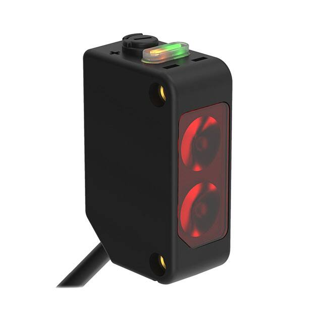
Key
1 Green LED: Power Indicator
2 Amber LED: Light Sensed Indicator (Flashes for Marginal Conditions)
3 Cutoff Point Adjustment Potentiometer
1 2 m (6.5 ft) PVC cabled models are listed for the complementary output models. 2 m (6.5 ft) and 9 m (30 ft) PVC cabled options are not available on IO-Link
models.
•
To order the 9 m (30 ft) PVC cable model, add the suffix "W/30" to the cabled model number. For example, Q20NAF200 W/30.
•
To order the 4-pin M8/Pico-style integral quick disconnect model, add the suffix "Q7" to the model number. For example, Q20NAF200Q7.
•
To order the 150 mm (6 in) PVC cable model with a 4-pin M12/Euro-style quick disconnect, add the suffix "Q5" to the model number. For
example, Q20NAF200Q5.
•
To order the 150 mm (6 in) PVC cable model with a 4-pin M8/Pico-style quick disconnect, add the suffix "Q" to the model number. For example,
Q20NAF200Q.
•
Models with a quick disconnect require a mating cordset.
Original Document
208516 Rev. B
31 July 2019
208516
�WORLD-BEAM® Q20 Sensor with Background Suppression
Installation Instructions
Sensor Orientation
Optimize detection reliability and minimum object
separation performance with correct sensor-to-target
orientation. To ensure reliable detection, orient the
sensor as shown in relation to the target to be detected.
Figure 1. Optimal Orientation of Target to Sensor
Wiring Diagrams
Cabled wiring diagrams are shown. Quick disconnect wiring diagrams are functionally identical.
NPN Output
1
4
2
1
+
10-30V dc
–
3
4
Load
2
Load
4-pin M8/Pico-style Male QD
2
1
–
10-30V dc
+
IO-Link with PNP Output
Load
Load
1
IO-Link
3
PNP Output
4
+
CH1
Load
3
2
Key
10–30 V dc
1 = Brown
2 = White
3 = Blue
4 = Black
–
CH2
Load
4-pin M12/Euro-style Male QD
4
1
2
3
4
3
Set up the Sensor
Background Suppression Mode: Objects beyond the set cutoff distance will not be detected. Background suppression mode can
be used in most situations with varying object colors and positions or with varying background conditions.
To ensure reliable background suppression, a minimum separation distance between the object and the background is necessary.
Object
Background
X: Distance to the Object
Y: Minimum Separation Between the Object and the
Background
Set the cutoff distance approximately midway between the
farthest object and the closest background.
Y
X
Cutoff
Distance
Figure 2. Minimum Separation Distance
1. Mount the sensor with the darkest object at the longest application distance.
The distance to the object must be less than shown in Figure 4 (p. 5) for your object color.
2
www.bannerengineering.com - Tel: + 1 888 373 6767
P/N 208516 Rev. B
�WORLD-BEAM® Q20 Sensor with Background Suppression
2.
3.
4.
5.
6.
Turn the adjustment potentiometer counter-clockwise until the amber indicator turns off.
Turn the adjustment potentiometer clockwise until the amber indicator turns on.
Replace the darkest object with the brightest background at the closest application distance.
Turn the adjustment potentiometer clockwise until the amber indicator turns on.
Turn the adjustment potentiometer counter-clockwise approximately half of the adjustment rotation from the previous step.
This places the cutoff distance approximately half-way between the object and the background switch points. If sufficient
separation exists between the object and background, the sensor is ready for operation.
IO-Link Interface
IO-Link is a point-to-point communication link between a master device and sensor. Use IO-Link to parameterize sensors and
transmit process data automatically.
For the latest IO-Link protocol and specifications, see www.io-link.com.
Each IO-Link device has an IODD (IO Device Description) file that contains information about the manufacturer, article number,
functionality etc. This information can be easily read and processed by the user. Each device can be unambiguously identified via
the IODD as well as via an internal device ID. Download the Q20's IO-Link IODD package (p/n 209012) from Banner Engineering's
website at www.bannerengineering.com.
Banner has also developed Add On Instruction (AOI) files to simplify ease-of-use between the Q20, multiple third-party vendors'
IO-Link masters, and the Logix Designer software package for Rockwell Automation PLCs. Three types of AOI files for Rockwell
Allen-Bradley PLCs are listed below. These files and more information can be found at www.bannerengineering.com.
Process Data AOIs—These files can be used alone, without the need for any other IO-Link AOIs. The job of a Process Data AOI is
to intelligently parse out the Process Data word(s) in separate pieces of information. All that is required to make use of this AOI is
an EtherNet/IP connection to the IO-Link Master and knowledge of where the Process Data registers are located for each port.
Parameter Data AOIs—These files require the use of an associated IO-Link Master AOI. The job of a Parameter Data AOI, when
working in conjunction with the IO-Link Master AOI, is to provide quasi-realtime read/write access to all IO-Link parameter data in
the sensor. Each Parameter Data AOI is specific to a given sensor or device.
IO-Link Master AOIs—These files require the use of one or more associated Parameter Data AOIs. The job of an IO-Link Master
AOI is to translate the desired IO-Link read/write requests, made by the Parameter Data AOI, into the format a specific IO-Link
Master requires. Each IO-Link Master AOI is customized for a given brand of IO-Link Master.
Add and configure the relevant Banner IO-Link Master AOI in your ladder logic program first; then add and configure Banner IOLink Device AOIs as desired, linking them to the Master AOI as shown in the relevant AOI documentation.
Specifications
Supply Voltage
10 V dc to 30 V dc (10% maximum ripple within specified limits)
Maximum Power Consumption (exclusive of load)
Less than 300 mW
Output Response
1.7 milliseconds ON; 1.1 milliseconds OFF
Note: 200 millisecond delay on power-up; outputs do not conduct during this
time
Sensing Beam
Visible red LED, 640 nm
Adjustments
Single-turn adjustment potentiometer sets the cutoff distance between minimum
and maximum positions
Supply Protection Circuitry
Protected against reverse polarity and transient voltages
Repeatability
130 µs (standard mode)
Output Configuration
Solid-state complementary: open collector NPN or PNP, depending on
model
Rating: 50 mA per output
Output Voltage High: Greater than Vsupply - 2.5 V
Output Voltage Low: Less than 2.5 V
For loads less than 1 Meg Ohm
Protected against false pulse on power-up and continuous overload or
short circuit of outputs
Indicators
2 LED indicators on sensor top:
Green solid: Power on
Amber: Light sensed
Amber flashing: Marginal sensing condition
P/N 208516 Rev. B
Construction
ABS front housing and gain adjuster, PMMA lenses; Copolyamide rear housing
www.bannerengineering.com - Tel: + 1 888 373 6767
3
�WORLD-BEAM® Q20 Sensor with Background Suppression
Connections
2 m (6.5 ft) unterminated 4-wire PVC cable; 9 m (30 ft) unterminated 4wire PVC cable; 150 mm (6 in) PVC cable with a 4-pin M8/Pico-style
quick disconnect; 150 mm (6 in) PVC cable with a 4-pin M12/Euro-style
quick disconnect or Integral 4-pin M8/Pico-style quick disconnect,
depending on model
Models with a quick disconnect require a mating cordset
Required Overcurrent Protection
IO-Link Interface
Supports Smart Sensor Profile: Yes
Baud Rate: 38400 bps
Process Data Widths: 16 bits
IODD Files: Provides all programming options plus additional
functionality; please see the IO-Link Data Reference Guide for more
details
WARNING: Electrical connections must be made by
qualified personnel in accordance with local and
national electrical codes and regulations.
Overcurrent protection is required to be provided by end product application per
the supplied table.
Overcurrent protection may be provided with external fusing or via Current
Limiting, Class 2 Power Supply.
Supply wiring leads < 24 AWG shall not be spliced.
For additional product support, go to www.bannerengineering.com.
Supply Wiring (AWG)
Required Overcurrent Protection (Amps)
Environmental Rating
IEC IP67; NEMA 6
20
5.0
22
3.0
Operating Conditions
–20 °C to +60 °C (–4 °F to +140 °F)
95% relative humidity at 50 °C (non-condensing)
24
2.0
26
1.0
28
0.8
30
0.5
Vibration and Mechanical Shock
All models meet MIL-STD-202F, Method 201A (Vibration: 10 Hz to 60
Hz maximum, 0.06 inch (1.52 mm) double amplitude, 10G maximum
acceleration) requirements. Also meets IEC 60947-5-2 (Shock: 30G 11
ms duration, half sine wave) requirements.
Certifications
Dimensions
Cabled and Pigtail QD Models
20.0 mm
(0.79")
3.3 mm
(0.13")
12.0 mm (0.47")
1.8 mm
(0.07")
3.3 mm
(0.13")
Integral QD
Models
10.5 mm
(0.42")
25.4 mm
(1.00")
9.9 mm
(0.39")
32.0 mm
(1.26")
42.0 mm
(1.65")
2X M3 X0.5
Max. Torque
0.56 Nm (5 in. lbs.)
2 - M3 screws (12 mm)
washers included
Performance Curves
The minimum sensing range for 6% reflectivity is 14 mm.
4
www.bannerengineering.com - Tel: + 1 888 373 6767
P/N 208516 Rev. B
�WORLD-BEAM® Q20 Sensor with Background Suppression
Q20EAF Minimum Separation Between Object and Background
40
Minimum Separation Object to Background
Dimension “Y” (mm)
10
Emitter Beam Diameter (mm)
9
8
7
6
5
4
3
2
1
0
0
20
40
60
80
100
120
140
160
180
200
Object/Background
30
gray/white
20
black/white
10
white/white
0
25
50
75
100
125
150
175
200
Distance to Object, Dimension “X” (mm)
Range (mm)
Figure 3. Emitter Beam Diameter graph
Figure 4. Minimum Separation Between Object and Background
Excess Gain Curves
1000
EXCESS GAIN
EXCESS GAIN
1000
100
10
100
10
1
1
1
10
100
1000
1
10
100
1000
DISTANCE (mm)
DISTANCE (mm)
Figure 5. 30 mm Excess Gain
Figure 6. 200mm Excess Gain
Accessories
Quick-Disconnect (QD) Cordsets
4-Pin Threaded M12/Euro-Style Cordsets—Single Ended
Model
Length
MQDC-406
1.83 m (6 ft)
MQDC-415
4.57 m (15 ft)
MQDC-430
9.14 m (30 ft)
MQDC-450
15.2 m (50 ft)
MQDC-406RA
1.83 m (6 ft)
MQDC-415RA
4.57 m (15 ft)
MQDC-430RA
9.14 m (30 ft)
Style
Dimensions
44 Typ.
Straight
M12 x 1
ø 14.5
P/N 208516 Rev. B
15.2 m (50 ft)
1
4
32 Typ.
[1.26"]
30 Typ.
[1.18"]
Right-Angle
MQDC-450RA
Pinout (Female)
2
3
1 = Brown
2 = White
3 = Blue
4 = Black
M12 x 1
ø 14.5 [0.57"]
www.bannerengineering.com - Tel: + 1 888 373 6767
5
�WORLD-BEAM® Q20 Sensor with Background Suppression
4-Pin Snap-on M8/Pico-Style Cordsets—Single Ended
Model
Length
Style
Dimensions
Pinout (Female)
32 Typ.
PKG4-2
2 m (6.56 ft)
Straight
ø 9.0
2 m (6.56 ft)
Right-Angle
2
1
3
29 Typ.
PKW4Z-2
4
1 = Brown
2 = White
3 = Blue
4 = Black
15 Typ.
ø 10.9
4-Pin Threaded M8/Pico-Style Cordsets—Single Ended
Model
Length
PKG4M-2
2 m (6.56 ft)
PKG4M-5
5 m (16.4 ft)
PKG4M-9
9 m (29.5 ft)
PKW4M-2
2 m (6.56 ft)
PKW4M-5
5 m (16.4 ft)
Style
Dimensions
35 Typ.
Straight
ø 9.5
M8 x 1
4
2
1
3
28 Typ.
1 = Brown
2 = White
3 = Blue
4 = Black
20 Typ.
Right Angle
PKW4M-9
Pinout (Female)
9 m (29.5 ft)
M8 x 1
ø 9.5
Mounting Brackets
SMBQ20L
• Sensor vertical base mount
• ±5° tip, ±7° swivel
• Stainless steel
16
4X
Ø3.2
40
16
4X
Ø3.2
4X
Ø3.4
6
Ø3.2
4X
Ø3.4
23
55
15
36
2X
Ø3.2
4X
Ø3.4
14
SMBQ20H
• Sensor horizontal flange mount
• ±10° swivel
• Stainless steel
SMBQ20LV
• Sensor vertical back mount
• ±10° tip
• Stainless steel
31
SMBQ20U
• Sensor vertical base mount with
protection
• ±22.5° swivel
• Stainless steel
www.bannerengineering.com - Tel: + 1 888 373 6767
23
4X
Ø3.2
39
12.5
34
4X
Ø3.2
P/N 208516 Rev. B
�WORLD-BEAM® Q20 Sensor with Background Suppression
Banner Engineering Corp. Limited Warranty
Banner Engineering Corp. warrants its products to be free from defects in material and workmanship for one year following the date of shipment. Banner Engineering Corp. will repair or
replace, free of charge, any product of its manufacture which, at the time it is returned to the factory, is found to have been defective during the warranty period. This warranty does not
cover damage or liability for misuse, abuse, or the improper application or installation of the Banner product.
THIS LIMITED WARRANTY IS EXCLUSIVE AND IN LIEU OF ALL OTHER WARRANTIES WHETHER EXPRESS OR IMPLIED (INCLUDING, WITHOUT LIMITATION, ANY WARRANTY OF
MERCHANTABILITY OR FITNESS FOR A PARTICULAR PURPOSE), AND WHETHER ARISING UNDER COURSE OF PERFORMANCE, COURSE OF DEALING OR TRADE USAGE.
This Warranty is exclusive and limited to repair or, at the discretion of Banner Engineering Corp., replacement. IN NO EVENT SHALL BANNER ENGINEERING CORP. BE LIABLE TO
BUYER OR ANY OTHER PERSON OR ENTITY FOR ANY EXTRA COSTS, EXPENSES, LOSSES, LOSS OF PROFITS, OR ANY INCIDENTAL, CONSEQUENTIAL OR SPECIAL DAMAGES
RESULTING FROM ANY PRODUCT DEFECT OR FROM THE USE OR INABILITY TO USE THE PRODUCT, WHETHER ARISING IN CONTRACT OR WARRANTY, STATUTE, TORT,
STRICT LIABILITY, NEGLIGENCE, OR OTHERWISE.
Banner Engineering Corp. reserves the right to change, modify or improve the design of the product without assuming any obligations or liabilities relating to any product previously
manufactured by Banner Engineering Corp. Any misuse, abuse, or improper application or installation of this product or use of the product for personal protection applications when the
product is identified as not intended for such purposes will void the product warranty. Any modifications to this product without prior express approval by Banner Engineering Corp will
void the product warranties. All specifications published in this document are subject to change; Banner reserves the right to modify product specifications or update documentation at
any time. Specifications and product information in English supersede that which is provided in any other language. For the most recent version of any documentation, refer to:
www.bannerengineering.com.
For patent information, see www.bannerengineering.com/patents.
FCC Part 15 and CAN ICES-3 (B)/NMB-3(B)
This device complies with part 15 of the FCC Rules and CAN ICES-3 (B)/NMB-3(B). Operation is subject to the following two conditions:
1.
2.
This device may not cause harmful interference, and
This device must accept any interference received, including interference that may cause undesired operation.
This equipment has been tested and found to comply with the limits for a Class B digital device, pursuant to part 15 of the FCC Rules and CAN ICES-3 (B)/NMB-3(B). These limits are
designed to provide reasonable protection against harmful interference in a residential installation. This equipment generates, uses and can radiate radio frequency energy and, if not
installed and used in accordance with the instructions, may cause harmful interference to radio communications. However, there is no guarantee that interference will not occur in a
particular installation. If this equipment does cause harmful interference to radio or television reception, which can be determined by turning the equipment off and on, the user is
encouraged to try to correct the interference by one or more of the following measures:
•
Reorient or relocate the receiving antenna.
•
Increase the separation between the equipment and receiver.
•
Connect the equipment into an outlet on a circuit different from that to which the receiver is connected.
•
Consult the manufacturer.
© Banner Engineering Corp. All rights reserved
�