R-GAGE® QT50R-AFH Sensor
Datasheet
Radar-Based Sensors for Detection of Moving and Stationary Targets
•
•
•
•
•
•
•
FMCW radar detects moving and stationary objects
Higher sensitivity and longer range
Adjustable sensing field—ignores objects beyond setpoint
Easy setup and configuration of range, sensitivity, and output with simple DIP
switches
Sensing functions are unaffected by wind, falling rain or snow, fog, humidity, air
temperatures, or light
Sensor operates in Industrial, Scientific, and Medical (ISM) telecommunication band
Rugged IP67 housing withstands harsh environments
WARNING:
• Do not use this device for personnel protection
• Using this device for personnel protection could result in serious injury or death.
• This device does not include the self-checking redundant circuitry necessary to allow its use in
personnel safety applications. A device failure or malfunction can cause either an energized (on) or deenergized (off) output condition.
Models
Maximum
Range
Models 1
Connection
Supply Voltage
QT50R-US-AFH
Telecom Approval 2
Output
Telecom approved for US, Canada and Brazil
QT50R-EU-AFH
24 m (78 ft)
QT50R-KR-AFH
QT50R-TW-AFH
5-wire 2 m (6.5
ft) Integral cable
12 to 30 V DC
Telecom approved for Europe, UK, Australia, New
Zealand, China, and Japan
12 to 24 V DC
Telecom approved for South Korea
Telecom approved for Taiwan
12 to 30 V DC
QT50R-SG-AFH
Bipolar NPN/PNP
DIP-switch-selectable
normally open (NO) or
normally closed (NC)
Telecom approved for Singapore
Overview
The R-GAGE sensor emits a well-defined beam of high-frequency radio waves from an internal antenna. Some of this emitted
energy reflects back to the receiving antenna. Signal processing electronics in the sensor determine the distance from the sensor to
the object based on the time delay of the return signal. The sensor can be configured (via DIP switches) to sense objects up to a
specific distance, ignoring objects beyond this distance (also called background suppression).
Figure 1. R-GAGE setpoint
Setpoint
X
Y
D
1 Cabled models only are listed. To order the integral 5-pin M12 quick-disconnect fitting, add suffix "Q" to the model number (for example, QT50R-xx-AFHQ).
Quick-disconnect models require a mating cordset; see Quick Disconnect (QD) Cordsets on p. 6.
2 For additional countries, contact Banner Engineering.
Original Document
162359 Rev. J
11 June 2021
162359
�R-GAGE® QT50R-AFH Sensor
Setpoints
EU, KR Models
TW, US Models
X
Minimum setpoint distance
2 m (6.6 ft)
3.5 m (11.5 ft)
Y
Maximum setpoint distance
24 m (78.7 ft)
24 m (78.7 ft)
D
Dead Zone 3
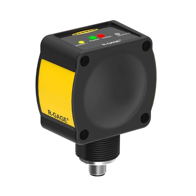
1. Power LED: Green (power ON)
2. Signal Strength LED: Red (flashes in proportion to the signal strength)
3. Output LEDs: Yellow (output energized); Red (configuration)
Figure 2. R-GAGE features
Access the DIP switches behind the threaded cap on the sensor back (not
shown)
R-GAGE setpoint distances, minimum and maximum (sensor will detect
objects up to setpoint and ignore objects beyond the setpoint)
Sensor Configuration
The sensing zone distance, sensitivity, and output configuration can be selected via the DIP switches on the back of the sensor. Use
the included spanner to open the screw-off cover on the back of the sensor and access the DIP switches.
Important: Tighten the DIP switch cover a full quarter turn after contact to maintain the watertight seal.
DIP Switch Functions
Switch
Function
1, 2, 3
Sensing distance (detects objects from sensor face to this point)
4, 5
Sensitivity (higher sensitivity sees weaker objects and has a larger beam pattern)
6
Normally open/normally closed output functionality
7, 8
Response Speed
DIP switch 1 is on the left and DIP switch 8 is on the right.
Distance Settings
* Default settings
Switch 1
Switch 2
Switch 3
0
0
0
0
0
0
1
0
Distance
EU, KR Models
TW, US Models
2 m (6.6 ft)
3.5 m (11.5 ft)
1
3 m (9.8 ft)
4 m (13.1 ft)
0
4 m (13.1 ft)
5 m (16.4 ft)
1
1
6 m (19.7 ft)
6 m (19.7 ft)
1*
0*
0*
8 m (26.2 ft)
8 m (26.2 ft)
1
0
1
12 m (39.4 ft)
12 m (39.4 ft)
1
1
0
16 m (52.5 ft)
16 m (52.5 ft)
1
1
1
24 m (78.7 ft)
24 m (78.7 ft)
Note: Highest sensitivity is achieved only if sensing distance is 8 m (26.2 ft) or less.
3 Typical dead zone: 0.4 m (1.3 ft) for moving and 1.0 m (3.3 ft) for stationary targets, but varies with target reflectivity
2
www.bannerengineering.com - Tel: + 1 888 373 6767
P/N 162359 Rev. J
�R-GAGE® QT50R-AFH Sensor
Note: Near-field sensitivity boost is enabled when set to 4 m (13.1 ft) or less.
Sensitivity Selection
Switch 4
Switch 5
Sensitivity
0*
0*
4 (Highest)
0
1
3 (High)
1
0
2 (Medium)
1
1
1 (Low)
* Default settings
Note: Use the sensitivity selection to ignore unwanted weak reflections within the field of view, and not to narrow
the beam width. Narrow-beam R-GAGE sensor models are available.
Output Configuration
Switch 6
Normally Open/Normally Closed
0*
Normally open
1
Normally closed
* Default settings
Response Speed
Switch 7
Switch 8
On Total (ms)
Off Total (ms)
Total (ms)
0
0
30
70
100
0*
1*
50
300
350
1
0
30
1000
1030
1
1
120
6000
6120
* Default settings
Windows
The R-GAGE sensor can be placed behind a glass or a plastic window, but the configuration must be tested and the distance from
the sensor to the window must be determined and controlled prior to installation. There is typically a 20% signal reduction when the
sensor is placed behind a window.
Polycarbonate at 4 mm thickness performs well in most situations, but the performance depends on filler materials. Thinner (1 to 3
mm) windows have high reflection. The amount of reflection depends on the material, thickness, and distance from the sensor to the
window.
Locate the sensor in a position of minimum reflection from the window, which will repeat every 6.1 mm of distance between the
sensor and the window. The positions of maximum reflection from the window repeat between the minimums, and decrease in effect
until the window is approximately 150 mm (5.9 in) away. Consult the factory for pre-tested window materials which can be used at
any distance without issue.
Additionally, the face of the window should be protected from flowing water and ice by use of a flow diverter or hood directly above
the window. Falling rain or snow in the air in front of the window, light water mist, or small beads on the face of the window are
typically not an issue. However, a thick, continuous surface of water or ice directly on the face of the window can be detected as a
dielectric boundary.
P/N 162359 Rev. J
www.bannerengineering.com - Tel: + 1 888 373 6767
3
�R-GAGE® QT50R-AFH Sensor
Wiring
There is no connection to the gray (gy) wire.
bn
+
12–30 V dc
–
bu
wh
bk
Note: Banner recommends that the shield wire (quickdisconnect cordsets only) be connected to earth ground or dc
common. Shielded cordsets are recommended for all quickdisconnect models.
Load 1
Load 2
gy
shield (QD cordset)
Specifications
Range
The sensor is able to detect a proper object (see Detectable Objects) from 1
m to 24 m (3.3 ft to 78.7 ft), depending on target
Detectable Objects
Objects containing metal, water, or similar high-dielectric materials
Operating Principle
Frequency modulated continuous-wave (FMCW) radar
Operating Frequency
US, TW Models: 24.075–24.175 GHz, ISM Band
EU, KR, SG Models: 24.050-24.250 GHz, ISM Band
Supply Voltage
12 V DC to 30 V DC, less than 100 mA, exclusive of load
For KR models: 12 V DC to 24 V DC, less than 100 mA exclusive of load
Supply Protection Circuitry
Protected against reverse polarity and transient overvoltages
Delay at Power-up
Less than 2 seconds
Operating Temperature
–40 °C to +65 °C (–40 °F to +149 °F)
Environmental Rating
IP67
Connections
Integral 5-wire 2 m (6.5 ft) cable or M12 Euro-style QD fitting. QD models
require a mating cordset
Certifications
Output Configuration
Bipolar NPN/PNP output, 150mA; DIP switch 6 selects N.O. (default) or N.C.
operation
Response Time
DIP switches 7 & 8 select ON/OFF response time
Adjustments
DIP-switch-configurable sensing distance, sensitivity, response time, and
output configuration
Construction
Housing: ABS/polycarbonate
Lightpipes: Acrylic
Access Cap: Polyester
Maximum Output Power
ERP: 3.3 mW, 5 dBm
EIRP: 100 mW, 20 dBm
Output Protection
Protected against short circuit conditions
Indicators
Power LED: Green (power ON)
Signal Strength LED: Red, flashes in proportion to signal strength. Steady
on at 4x excess gain. Only indicates signal amplitude, not target distance.
Output LEDs: Yellow (output energized) / Red (configuration)
See Figure 2 on p. 2
ETSI/EN 300 440
FCC part 15
RSS-210
ANATEL Category II
CMIIT Category G
ARIB STD T-73
KC mark - MSIP/RRA
NCC
IDA Singapore
for others, contact Banner Engineering
Country of Origin: USA
FCC ID: UE3QT50RUS—This device complies with Part 15 of the FCC Rules. Operation is subject to the following two conditions:
(1) this device may not cause harmful interference, and (2) this device must accept any interference received, including interference
that may cause undesired operation.
IC: 7044A-QT50RCA—This device complies with Industry Canada license-exempt RSS standard(s). Operation is subject to the
following two conditions: (1) this device may not cause interference, and (2) this device must accept any interference, including
interference that may cause undesired operation of the device.
Cet appareil est conforme aux CNR exempts de licence d'Industrie Canada. Son fonctionnement est soumis aux deux conditions
suivantes:(1) Ce dispositif ne peut causer des interférences; et(2) Ce dispositif doit accepter toute interférence, y compris les
interférences qui peuvent entraîner un mauvais fonctionnement de l'appareil.
4
www.bannerengineering.com - Tel: + 1 888 373 6767
P/N 162359 Rev. J
�R-GAGE® QT50R-AFH Sensor
Este equipamento não tem direito à proteção contra interferência prejudicial e
não pode causar interferência em sistemas devidamente autorizados.
SRD24-IO3B24100.2TR0.1 South Korea Class A Certification
A 급 기기 ( 업무용 방송통신기자재 )
이 기기는 업무용 (A 급 ) 으로 전자파적합기기로
서 판매자 또는 사용자는 이 점을 주의하시기
바라며 , 가정외의 지역에서 사용하는 것을 목
적으로 합니다 .
Beam Pattern
Typical Beam Pattern (with BRTR-CC20E Radar Target, Radar Cross
Section = 50 m2)
Typical Beam Pattern (with 4 different targets) at highest sensitivity level
Left-Right Beam Pattern
Left-Right Beam Pattern
20 m
20 m
Sensitivity 1
Sensitivity 4
10 m
3
Target 4
Target 1
4
10 m
4
3
2
2
1
0m
0m
10 m
10 m
20 m
1
20 m
0
10 m
20 m
30 m
40 m
0
Distance
1–4: Indicates sensitivity level
10 m
20 m
30 m
40 m
Distance
1: Weak Object (Radar cross section = 0.25 m2)
2: Car (Radar cross section = 3 m2)
3: Large Truck (Radar cross section = 50 m2)
4: Passenger Train (Radar cross section = 300 m2)
Note: The effective beam pattern depends on the sensitivity level and target properties.
P/N 162359 Rev. J
www.bannerengineering.com - Tel: + 1 888 373 6767
5
�R-GAGE® QT50R-AFH Sensor
Dimensions
74.1 mm
(2.92")
46.1 mm
(1.82")
37.0 mm
(1.46")
38.1 mm
(1.50")
4X Ø4.4 mm
(Ø 0.17")
33.0 mm
(1.30")
50.8 mm
(2.00")
66.0 mm
(2.60")
19.7 mm
(0.78")
R45.0 mm
(R1.77")
34.2 mm
(1.35")
37.0 mm
(1.46")
M30 X 1.5
ISO-6g
50.8 mm
(2.00")
Accessories
Quick Disconnect (QD) Cordsets
5-Pin Threaded M12 Cordsets with Shield—Single Ended
Model
Length
MQDEC2-506
2 m (6.56 ft)
MQDEC2-515
5 m (16.4 ft)
MQDEC2-530
9 m (29.5 ft)
MQDEC2-550
15 m (49.2 ft)
MQDEC2-506RA
2 m (6.56 ft)
MQDEC2-515RA
5 m (16.4 ft)
MQDEC2-530RA
9 m (29.5 ft)
Style
Dimensions
44 Typ.
Straight
M12 x 1
ø 14.5
15 m (49.2 ft)
1
4
32 Typ.
[1.26"]
30 Typ.
[1.18"]
Right-Angle
MQDEC2-550RA
Pinout (Female)
2
3
5
1 = Brown
2 = White
3 = Blue
4 = Black
5 = Gray
M12 x 1
ø 14.5 [0.57"]
Note: Pin 5 is not used.
6
www.bannerengineering.com - Tel: + 1 888 373 6767
P/N 162359 Rev. J
�R-GAGE® QT50R-AFH Sensor
Mounting Brackets
All measurements are listed in millimeters, unless noted otherwise.
SMB30SC
Swivel bracket with 30 mm
•
mounting hole for sensor
•
Black reinforced thermoplastic
polyester
•
Stainless steel mounting and
swivel locking hardware included
67
B
58
29
Hole center spacing: A=ø 50.8
Hole size: A=ø 7.0, B=ø 30.0
SMB30MM
12-ga. stainless steel bracket
•
with curved mounting slots for
versatile orientation
•
Clearance for M6 (¼ in)
hardware
•
Mounting hole for 30 mm sensor
57
70
C
57
B
A
A
Hole center spacing: A = 51, A to B = 25.4
Hole size: A = 42.6 x 7, B = ø 6.4, C = ø 30.1
Weather Deflectors and Shields
QT50RCK Weather Deflector
•
•
Required if the R-GAGE is
exposed to rain or snow
Prevents buildup of water or
ice from interfering with
sensor performance
QT50RWS Weather Shield
•
•
Coated to help repel water and
maximize signal strength
Hardware included for easy
installation and replacement
Banner Engineering Corp. Limited Warranty
Banner Engineering Corp. warrants its products to be free from defects in material and workmanship for one year following the date of shipment. Banner Engineering Corp. will repair or
replace, free of charge, any product of its manufacture which, at the time it is returned to the factory, is found to have been defective during the warranty period. This warranty does not
cover damage or liability for misuse, abuse, or the improper application or installation of the Banner product.
THIS LIMITED WARRANTY IS EXCLUSIVE AND IN LIEU OF ALL OTHER WARRANTIES WHETHER EXPRESS OR IMPLIED (INCLUDING, WITHOUT LIMITATION, ANY
WARRANTY OF MERCHANTABILITY OR FITNESS FOR A PARTICULAR PURPOSE), AND WHETHER ARISING UNDER COURSE OF PERFORMANCE, COURSE OF DEALING OR
TRADE USAGE.
This Warranty is exclusive and limited to repair or, at the discretion of Banner Engineering Corp., replacement. IN NO EVENT SHALL BANNER ENGINEERING CORP. BE LIABLE TO
BUYER OR ANY OTHER PERSON OR ENTITY FOR ANY EXTRA COSTS, EXPENSES, LOSSES, LOSS OF PROFITS, OR ANY INCIDENTAL, CONSEQUENTIAL OR SPECIAL
DAMAGES RESULTING FROM ANY PRODUCT DEFECT OR FROM THE USE OR INABILITY TO USE THE PRODUCT, WHETHER ARISING IN CONTRACT OR WARRANTY,
STATUTE, TORT, STRICT LIABILITY, NEGLIGENCE, OR OTHERWISE.
Banner Engineering Corp. reserves the right to change, modify or improve the design of the product without assuming any obligations or liabilities relating to any product previously
manufactured by Banner Engineering Corp. Any misuse, abuse, or improper application or installation of this product or use of the product for personal protection applications when the
product is identified as not intended for such purposes will void the product warranty. Any modifications to this product without prior express approval by Banner Engineering Corp will void
the product warranties. All specifications published in this document are subject to change; Banner reserves the right to modify product specifications or update documentation at any time.
Specifications and product information in English supersede that which is provided in any other language. For the most recent version of any documentation, refer to:
www.bannerengineering.com.
For patent information, see www.bannerengineering.com/patents.
© Banner Engineering Corp. All rights reserved
�