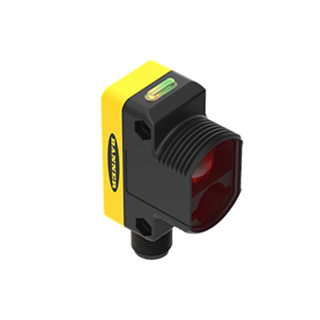
WORLD-BEAM® QS30ELVC Series
Expert™ Clear Object Non-Polarized Retroreflective Sensor
Features
• Reliable detection of clear, translucent, or opaque targets — including mirror-like
surfaces
• Automatic compensation algorithm compensates for dust or contamination on the
sensor or reflector and for ambient temperature changes
• 3 selectable thresholds based on type of target being detected
• Easy configuration via push buttons or remote wire
• Easy-to-read operating status indicators
• Rugged housing for harsh environments; rated IP67 (NEMA 6), 1200 psi washdown
per NEMA PW12
• Compact housing, mounting versatility — 30 mm threaded barrel or side-mount
CLEAR PLASTIC
RETRO
Models
Model
QS30ELVC
QS30ELVCQ
Sensing Range and Use*
100 mm to 2 m (3.9" to 78")
Light SET for clear object detection
Cable**
Supply Voltage
Output
2 m (6.5') 5-wire cable
10 to 30V dc
Bipolar (NPN and PNP)
Integral 5-pin Euro-Style QD
* Operation at shorter and longer distances possible. Contact factory for applications assistance.
** �For 9 m (30') cable, add suffix “W/30” to the model number (e.g., QS30ELVC W/30).
For 150 mm (6") pigtail with a 5-pin Euro-style connector, add suffix “Q5” to the model number (e.g., QS30ELVCQ5).
For 150 mm (6") PUR cable with 5-pin threaded Euro-Style QD, add suffix “QPMA” to the model number (e.g. QS30ELVCQPMA).
A model with a QD connector requires a mating cordset (see page 9).
WARNING . . . Not To Be Used for Personnel Protection
Never use these products as sensing devices for personnel protection. Doing so could lead to serious injury or death.
These sensors do NOT include the self-checking redundant circuitry necessary to allow their use in personnel safety applications. A
sensor failure or malfunction can cause either an energized or de-energized sensor output condition. Consult your current Banner
Safety Products catalog for safety products which meet OSHA, ANSI and IEC standards for personnel protection.
Printed in USA
01/09
P/N 139760 rev. A
�WORLD-BEAM® QS30ELVC Series
Overview
Amber Output LED
Green Power ON LED
Configuration
Push Buttons
The QS30ELVC is an easy-to-use, high-performance retroreflective sensor optimized for
detection of clear, translucent, or opaque objects. The optical design of the sensor ensures
reliable detection of PET bottles, glass containers, and optically engineered surfaces such
as mirrors, LCD glass with polarizing films, or semi-conductor wafers. The sensor will not be
tricked by specular reflections from the object under normal operating conditions.
Switching
Threshold
Bargraph Display (Red)
The compact housing has a large, easy-to-see bargraph display for easy configuration
and status monitoring during operation. The sensor housing can be side-mounted, using
integral mounting holes, or front-mounted, via the 30 mm threaded barrel. A wide assortment
of mounting brackets are also available for applications requiring adjustability or robust
mechanical protection.
The QS30ELVC is configured for operation using the Light SET procedure described on page
4. The sensor is simply aligned to the included retroreflective target and the Light SET is
initiated either via the push button or the remote wire input. A reliable detection is assured
when the appropriate threshold for clear, translucent or dark object is selected.
Configuration Display
(Amber)
Figure 1. Features
Continued reliable operation is maintained as the thresholds adapt to changing signal levels
over time using Banner Engineering’s auto compensation tracking algorithm. The sensor
tracks the amount of light returned at every opportunity and makes fine adjustments to the
switching threshold as required due to dust or contamination in the environment building up
on the lens window or reflector. If the retroreflector is cleaned, returning the light to its original
level, the sensor quickly adapts and continues operating with no need to perform another
Light SET procedure.
The sensor can recover from a cold power-up by re-using the stored threshold values from the
last Light SET procedure. You only need to perform the Light SET procedure if the sensor is
moved or the sensor to reflector separation distance is changed.
The sensor ships from the factory as a DARK OPERATE (DO), non-polarized retroreflective
sensor with auto compensation enabled for easy set-up and reliable operation. The automatic
compensation tracking algorithm can be disabled if required through the user SETUP buttons
or the remote teach wire.
Indicators
The sensor’s compact housing has a large, easy-to-see bargraph display plus bright
LEDs for easy configuration and status monitoring during operation. Sensor power and
output state are indicated by the green and amber LEDs located at the top of the sensor.
Sensor configuration is indicated by the 5-segment amber display. Signal strength relative
to the switchpoint is indicated by the 3-segment red Signal bargraph (see Figure 2).
Clear
Medium
Dark
Received light level is greater
than switching threshold
Received light level is greater
than switching threshold
Received light level is greater
than switching threshold
8-16% of light SET level is being blocked
16-32% of light SET level is being blocked
32-64% of light SET level is being blocked
> 16% of light SET level is being blocked
> 32% of light SET level is being blocked
> 64% of light SET level is being blocked
Figure 2. Signal strength relative to the switchpoint
2 P/N 139760 rev. A
Banner Engineering Corp. • Minneapolis, MN U.S.A
www.bannerengineering.com • Tel: 763.544.3164
�WORLD-BEAM® QS30ELVC Series
Applications
Clear Bottle or Object Detection
1. Mount the retroreflector.
2. �Align the sensor to the retroreflector.
3. Perform Light SET (page 4) with no object present.
4. �Using Switchpoint Adjustment (page 6), select the darkest switchpoint which reliably detects
the object. Medium level (16% below the signal from the retroreflector) will work for most
applications. Dark level will provide more robust detection under difficult environmental
conditions (e.g. dust, vibration, etc).
Clear Bottle or Object Counting
1. Mount the retroreflector.
2. �Align the sensor to the retroreflector.
3. Disable the auto compensation function. Allow for 10 minute sensor warm-up period.
4. Position the bottles or objects so the beam is passing through the gap between the bottles.
5. Perform Light SET (page 4) on the gap condition.
6. �Using Switchpoint Adjustment (page 6), select the darkest switchpoint which reliably detects
the object. Medium level (16% below the signal from the retroreflector) will work for most
applications. Dark level may provide more robust detection under difficult environmental
conditions (e.g. dust, vibration, etc).
Reflective Object Detection
1. Mount the retroreflector.
2. �Align the sensor to the retroreflector.
3. Perform Light SET (page 4) with no object present.
4. �Using Switchpoint Adjustment (page 6), select clear or medium switchpoint percentage (8%
or 16% below the signal from the retroreflector). This will reduce the chance of specular
reflection affecting the sensor.
�
Banner Engineering Corp. • Minneapolis, MN U.S.A
www.bannerengineering.com • Tel: 763.544.3164
P/N 139760 rev. A 3
�WORLD-BEAM® QS30ELVC Series
Location of switchpoint
Single-Point Light SET
(+)
• �Useful for clear object detection and other applications with small variations in contrast.
(-) Offset based on
selected configuration
Output ON
• �Sets a switchpoint at 8 (clear), 16 (medium) or 32 (dark) percent below the signal from the
retroreflector.
Darkest
(no signal)
• �Switchpoint position is selectable using the “+” and “-” buttons. Select 8, 16, or 32
percent (Switchpoint Selection).
Output OFF
Most Light
(saturated
signal)
Sensor
Switchpoint
Learned
Signal from
Retro Target
• �Sensor must be aimed at the reflector during the SET process. All conditions darker than
the switchpoint condition result in ON output (Dark Operate). Output ON and OFF conditions
can be reversed by changing Light/Dark Operate in SETUP mode (factory setting: Dark
Operate).
Figure 3. �Low-contrast SET (Dark Operate
shown)
or
Set Switchpoint
Push Buttons
• Align sensor to reflector
• Press and hold “+”
> 2 seconds
Remote
• Align sensor to reflector
• Single-pulse remote line
T
Green Power LED: OFF
Amber Output LED: ON
Bargraph: �Top two signal LEDs
T
T
alternate
flashing
T
T
T
T
T
T
Sensor Feedback
Indicators
0.04 seconds ≤ T ≤ 0.8 seconds
T
T
Switchpoint
Accepted
T Power
T LED: ON
Green
Amber Output LED: ON (LO) or OFF (DO)
Bargraph: Appropriate LED ON
• �Sensor
mode
T returns
T to RUN
T
T with
new settings
T
T
T
Switchpoint Unacceptable
Green Power LED: ON
Amber Output LED: Flashing (Alarm State*)
Bargraph: All OFF
* See page 6
4 P/N 139760 rev. A
Banner Engineering Corp. • Minneapolis, MN U.S.A
www.bannerengineering.com • Tel: 763.544.3164
�WORLD-BEAM® QS30ELVC Series
SETUP Mode
SETUP mode is used to change sensor configuration:
• Light or Dark operate
• Enable or disable automatic compensation algorithm
If SETUP mode programming is interrupted and remains inactive for 60 seconds, the
sensor returns to RUN mode with the most recent settings (i.e., exits and saves current
selection).
SETUP mode operates in the “background”, while the outputs are active; changes are
updated instantly.
The sensor can be configured using the remote line (see page 7).
Push Button
Result
0.04 seconds ≤ “Click” ≤ 0.8 seconds
Access
SETUP Mode
• �Press and hold both push buttons > 2 seconds
or
flash current setup
• �Click either push button until LEDs show desired settings
Select Setting Combination
Green Power LED: OFF
Amber Output LED: Remains active
Bargraph: �Status indicators (LO and AUTO)
or
Sensor rotates through four setting combinations, in the
following order:
Setting Combination
Auto LED
LO LED
Auto Compensation ON/DO*
ON
OFF
Auto Compensation ON/LO
ON
ON
Auto Compensation OFF/LO
OFF
ON
Auto Compensation OFF/DO
OFF
OFF
* Factory default setting
Return to
RUN Mode
• �Press and hold both push buttons > 2 seconds
�
Banner Engineering Corp. • Minneapolis, MN U.S.A
www.bannerengineering.com • Tel: 763.544.3164
or
Green Power LED: ON
Amber Output LED: Remains active
Bargraph: Indicates current setup
• �Sensor returns to RUN mode
with new settings
P/N 139760 rev. A 5
�WORLD-BEAM® QS30ELVC Series
Switchpoint Selection
The switchpoint can be selected during RUN mode and is accomplished via the push
buttons or the remote wire (see Remote Line TEACH, page 7).
Switchpoint selection via push buttons:
• �Press “+” and “-” to select desired switchpoint
• �Three possible choices; 8, 16 or 32 percent below the signal from the retroreflector.
Selection does not wrap around.
The sensor continues operating normally with the newly selected threshold value. It is not
necessary to repeat the light SET.
T
T
Push Button Disable
T
T
T
T
T
T may
T Tbe used to disable
In addition to its configuration function,
Remote Configuration
the push buttons for security. Disabling the push buttons prevents undesired tampering
with the configuration settings. The Green Power LED blinks 4 times if a push button is
pressed while they are locked out. The sensor continues operating normally and ignores
the button press. Connect the gray wire of the sensor as described on page 2, and fourpulse to either enable or disable the push buttons:
T
T
T
T
T
T
T
0.04 < T < 0.8 s
Alarm State
T
T
T
T
The QS30ELVC Alarm State indicates that the sensor requires attention. In all situations,T the alarm
byTrealigning the sensor to
T canTbe cleared
T
the retroreflector, cleaning the sensor or retroreflector of contamination, and performing a Light SET to establish a valid light signal.
Alarm State is indicated by:
• Amber Output LED flashing T
T
• All 3 Red Signal LEDs OFF
• �Output forced to blocked state (i.e. if sensor is in dark operate (DO), the output is conducting)
The sensor may enter Alarm State for three reasons:
1. �The sensor may be in Alarm State when first powered up. This is normal operation and does not indicate a problem with the sensor.
The Alarm State will be cleared when a valid Light SET is performed.
2. �The sensor will enter Alarm State if the Light SET procedure fails. This indicates the sensor did not receive enough light from the
retroreflector for reliable detection. Realign the sensor to the retroreflector, making sure all optical surfaces are free of contamination.
�If the automatic compensation algorithm is enabled, the sensor may recover at this point and begin operating normally. It is not
necessary to repeat the Light SET procedure. If automatic compensation has been disabled, the sensor will remain in the Alarm State
until the alignment has been corrected and a Light SET is successfully completed.
3. �The sensor can enter Alarm State if the auto compensation algorithm is enabled and the sensor has automatically adjusted the
threshold as much as possible. The sensor and retroreflector should be cleaned, or the sensor should be realigned to the retroreflector.
The sensor will automatically adapt to the new light level, or a Light SET can be performed to reestablish the light level.
In any case, the sensor can be returned to normal operation by ensuring a clean optical path, aligning the sensor to the retroreflector, and
performing a Light SET procedure on the sensor.
6 P/N 139760 rev. A
Banner Engineering Corp. • Minneapolis, MN U.S.A
www.bannerengineering.com • Tel: 763.544.3164
�WORLD-BEAM® QS30ELVC Series
Remote Line TEACH
General Notes
• Connect the gray wire of the sensor to ground (0V dc), with a remote programming switch connected between them
T
• Run Mode is the sensor’s normal operating condition
T
T
T
T
T
• The duration of each Pulse is defined as “T”: 0.04 < T < 0.8 s
T
T
T
• A Hold will exit TEACH MODE and return to Run Mode with previously saved changes. The duration of a Hold is: T > 2 s
• A Timeout will occur if a condition is not registered within 60 seconds, causing the sensor Tto return to Run Mode (during sensor configuration only)
• Sensor configuration user feedback shown on Green LED. See flowT chart below.
T
T
Run Mode
Power LED ON,
All other LEDs in normal
operating condition
Exit
T
1x
T
T
Light SET
T
T
T
T
Power LED OFF,
Red Signal LED Flashing
2x
Basic Configuration Menu
Power LED OFF
LO and current threshold LEDs Flashing
1x
LO
LO LED ON
DO (default )
LO LED OFF
8%
Clear Bottle
2x
3x
4x
16% (default )
Medium Bottle
32%
Dark Bottle
5x
2 s Hold
60 second Timeout
3x
Advanced Sensor
Configuration Menu
Power LED OFF
Auto LED Flashing
1x
Push button
enabled (default )
Flash Power 1x,
Repeat twice
Push button
disabled
Flash Power 2x,
Repeat twice
Auto. comp.
enabled (default )
Auto LED ON
Auto. comp.
disabled
Auto LED OFF
2x
3x
4x
2 s Hold
60 second Timeout
4x
Push button enable /disable
(legacy method )
Flash Power:
1x for enabled , Repeat twice
2x for disabled, Repeat twice
8x
Restore factory defaults
�
Banner Engineering Corp. • Minneapolis, MN U.S.A
www.bannerengineering.com • Tel: 763.544.3164
All LEDs off for 1 s
P/N 139760 rev. A 7
�WORLD-BEAM® QS30ELVC Series
Specifications
Sensing Beam
660 nm visible red LED
Sensing Range and Use
100 mm to 2 m (3.9" to 78"); Light SET for clear object detection
Supply Voltage
10 to 30V dc (10% max. ripple) @ 25 mA max current, exclusive of load
Supply Protection Circuitry
Protected against reverse polarity, over voltage, and transient voltages
Delay at Power-Up
250 ms; outputs do not conduct during this time
Output Configuration
Bipolar: 1 current sourcing (PNP) and 1 current sinking (NPN)
Output Ratings
150 mA maximum load; see Application Note 1
OFF-state leakage current: < 50 µA at 30V dc
ON-state saturation voltage:
NPN: < 200 mV @ 10 mA; < 1V @ 150 mA
PNP: < 1.25V @ 10 mA; < 2V @ 150 mA
Output Protection
Protected against output short-circuit, continuous overload, transient over-voltages, and false pulse on power up
Output Response Time
500 microseconds
Repeatability
150 microseconds
Adjustments
2 push buttons and remote wire
• Easy push-button configuration and deterministic remote wire configuration
• Select from 3 standard thresholds based on object being detected
• Light Operate/Dark Operate configuration options selectable via push buttons or remote wire
• Push-button lockout (from remote wire only)
Indicators
Green LED: Power ON and feedback on configuration and remote wire pulses
Amber LED: Output conducting or error condition (flashing)
3-Segment Red Signal Bargraph: Signal strength (excess gain), relative to switchpoint
5-Segment Amber Display: Sensor Configuration
Construction
ABS plastic housing; acrylic lens cover
Environmental Rating
Leakproof design rated IEC IP67 (NEMA 6); PW12 1200 PSI washdown
Connections
5-conductor 2 m (6.5’) PVC cable, 9 m (30’) PVC cable, 150 mm (6") pigtail with a 5-pin Euro-style connector,
150 mm (6") PUR cable with 5-pin threaded Euro-Style QD or 5-pin integral Euro-style quick-disconnect fitting
Operating Conditions
Temperature: -10° to +55°C (+14° to 122°F),
Max. relative humidity: 95% @ 50°C (non-condensing)
Vibration and Mechanical
Shock
All models meet Mil. Std. 202F requirements. Method 201A (Vibration: 10 to 60 Hz max. double amplitude 0.06",
maximum acceleration 10G). Also meets IEC 947-5-2 requirements: 30G, 11 ms duration, half sine wave.
Application Notes
1. If supply voltage is > 24V dc, derate maximum output current 1 mA/°C above 25°C
Certifications
CE Pending
Hookups
Cabled Models
bn
bu
wh
bk
gy
Load
Load
QD Models
+
10 - 30V dc
–
150 mA max. load
Remote Teach
bn
bu
wh
bk
gy
Load
Load
+
10 - 30V dc
–
150 mA max. load
Remote Teach
Note: Pink wire not used
8 P/N 139760 rev. A
Banner Engineering Corp. • Minneapolis, MN U.S.A
www.bannerengineering.com • Tel: 763.544.3164
�WORLD-BEAM® QS30ELVC Series
Dimensions
Cabled Models
QD Models
35.0 mm
(1.38")
22.0 mm
(0.87")
32.5 mm
(1.28")
12.5 mm
(0.49")
3.5 mm
(0.14")
1.3 mm
(0.05")
Receiver
17.6 mm
(0.69")
44.0 mm
(1.73")
33.0 mm
(1.30")
5.0 mm
(0.20")
2 x ø3.3 mm (0.125")
max. torque
0.7 Nm (6 in lbs)
M30 x 1.5 Thread
max. torque
6 Nm (53 in lbs)
with included 30 mm
mounting nut
Emitter
28.8 mm
(1.13")
13.0 mm
(0.51")
Hardware Included:
(10) M3 x 0.5 x 28 stainless
steel machine screws, nuts and
washers
Accessories
Quick-Disconnect Cables
Style
Model
Length
5-pin
Euro-style
straight
MQDC1-506
MQDC1-515
MQDC1-530
2 m (6.5')
5 m (15')
9 m (30')
Dimensions
Pinout
ø 15 mm
(0.6")
44 mm max.
(1.7")
M12 x 1
Blue Wire
Black Wire
38 mm max.
(1.5")
5-pin
Euro-style
right-angle
MQDC1-506RA
MQDC1-515RA
MQDC1-530RA
2 m (6.5')
5 m (15')
9 m (30')
White Wire
Brown Wire
Gray Wire
38 mm max.
(1.5")
M12 x 1
ø 15 mm
(0.6")
�
Banner Engineering Corp. • Minneapolis, MN U.S.A
www.bannerengineering.com • Tel: 763.544.3164
P/N 139760 rev. A 9
�WORLD-BEAM® QS30ELVC Series
Mounting Brackets
NOTE: Other sensor models shown on some views below.
SMBQS30L
• �Right-angle bracket for cabled sensors
• �14-gauge stainless steel
• ± 12° tilt adjustment
• �Clearance for M4 (#8) hardware
SMBQS30LT
• �Tall right-angle bracket for QD sensors with straight
cordset connectors
• �14-gauge stainless steel
• ± 8° tilt adjustment
20°
20°
R35.0 mm
R35.0 mm
ø4.3 mm
44.0 mm
ø4.3 mm
44.0 mm
4.5 mm
4.5 mm
24.0 mm
11.0 mm
24.0 mm
11.0 mm
22.0 mm
R1.7 mm
22.0 mm
R33.0 mm
91.4 mm
33.0 mm
64.4 mm
R33.0 mm
24°
1.9 mm
SMBQS30Y
86.4 mm
16 mm
59.4 mm
1.9 mm
• �Heavy-duty die-cast bracket with M18 vertical
mounting option
• �± 8° tilt adjustment for cabled sensors
• �Nuts and lockwasher included
SMB30SC
50.8 mm
M30 x 1.5
internal
• �Swivel bracket
with 30 mm mounting hole for sensor
thread
• � �Black reinforced thermoplastic polyester
• �Stainless steel mounting and swivel locking hardware
included
58.7 mm
2 X R 33.0 mm
30.0 mm
17.0 mm
4 X Ø 3.3 mm
7.0 mm
66.5 mm
33 mm
56 mm
50.8 mm
M30 x 1.5
internal
thread
12.7 mm
M18 X 1
18.0 mm
26.5 mm
16.35 mm
58.7 mm
30.0 mm
13.3 mm
24.0 mm
35.0 mm
66.5 mm
29.0 mm
12.7 mm
Other Compatible Mounting Brackets (see Banner Photoelectric catalog or website for more information):
• SMB30MM
• SMB30A
• SMB30FA
29.0 mm
10 P/N 139760 rev. A
Banner Engineering Corp. • Minneapolis, MN U.S.A
www.bannerengineering.com • Tel: 763.544.3164
�WORLD-BEAM® QS30ELVC Series
Retroreflective Targets
Banner offers a wide selection of high-quality retroreflective targets. See the Accessories section of your
current Banner Photoelectric Sensors catalog for complete information. NOTE: QS30ELVC sensors require
corner cube type, large facet retroreflective targets only. Microprism and flexible tape reflectors are not recommended.
• �Corner-cube reflector
• 1.0 reflectivity factor*
• �Max. temp. +50° C (+122° F)
• Supplied with sensor
BRT2X2LVC
8.9 mm
51 mm
56 mm
10 mm
51 mm
30 mm
BRT40X19A
4.2 mm x 14.2 mm Slot (2)
Clear
Acrylic
Lens
• �Corner-cube reflector
• 1.2 reflectivity factor*
• �Max. temp. +50° C (+122° F)
• Supplied with sensor
19.3 mm
7.3 mm
• �Corner-cube reflector
• 3.0 reflectivity factor*
• Max. temp. +50° C (+122° F)
• Optional
BRT92X92C
100 mm
9 mm
92 mm
100 mm
61 mm
3.5 mm
50.0 mm
92 mm
60.2 mm
ø4.0 mm
Clear
Acrylic
Lens
White
Base
3.5 mm
*Reflectivity factor when compared with the standard BRT-3 reflector
�
Banner Engineering Corp. • Minneapolis, MN U.S.A
www.bannerengineering.com • Tel: 763.544.3164
P/N 139760 rev. A 11
�WORLD-BEAM® QS30ELVC Series
WARRANTY: Banner Engineering Corp. warrants its products to be free from defects for one year. Banner Engineering
Corp. will repair or replace, free of charge, any product of its manufacture found to be defective at the time it is returned
to the factory during the warranty period. This warranty does not cover damage or liability for the improper application of
Banner products. This warranty is in lieu of any other warranty either expressed or implied.
P/N 139760 rev. A
Banner Engineering Corp., 9714 Tenth Ave. No., Minneapolis, MN USA 55441 • Phone: 763.544.3164 • www.bannerengineering.com • Email: sensors@bannerengineering.com
�