WORLD-BEAM® QS18 Universal Voltage
Sensors
Datasheet
•
•
•
•
•
•
Easily fits or retrofits almost any mounting configuration
Exceptional optical performance in a compact right-angle housing
20 V ac/dc to 140 V ac/dc or 20 V ac/dc to 270 V ac/dc operation with P-MOSFET or NMOSFET output, depending on model (see Specifications)
Bright LED operating status indicators, visible from 360°
Rugged, sealed housing, protected circuitry, 1200 PSI washdown
Versatile mounting: front- and base-mount (M18), side-mount, and retrofit brackets
WARNING: Not To Be Used for Personnel Protection
Never use this device as a sensing device for personnel
protection. Doing so could lead to serious injury or death. This
device does not include the self-checking redundant circuitry necessary to
allow its use in personnel safety applications. A sensor failure or
malfunction can cause either an energized or de-energized sensor output
condition.
Model
Sensing Mode / LED
Output Type 1
Sensing Range
QS18WE
QS18ANWR
QS18RNWR
QS18APWR
N/A (Emitter)
L.O.
940 nm Infrared
20 m (66 ft)
Effective Beam: 10 mm (0.4
in)
OPPOSED
D.O.
L.O.
QS18RPWR
D.O.
QS18ANWLP
L.O.
QS18RNWLP
D.O.
QS18APWLP
660 nm Visible Red
P
3.5 m (12 ft)
POLAR RETRO
QS18RPWLP
L.O.
D.O.
QS18ANWLV
L.O.
QS18RNWLV
D.O.
QS18APWLV
660 nm Visible Red
6.5 m (21 ft)
RETRO
L.O.
QS18RPWLV
D.O.
QS18ANWDL
L.O.
QS18RNWDL
QS18APWDL
624 nm Visible Red
450 mm (18 in)
DIFFUSE
D.O.
L.O.
QS18RPWDL
D.O.
QS18ANWDXL
L.O.
QS18RNWDXL
D.O.
QS18APWDXL
850 nm Infrared
1 m (39 in)
DIFFUSE
QS18RPWDXL
L.O.
D.O.
N-MOSFET (Sinking)
P-MOSFET (Sourcing)
N-MOSFET (Sinking)
P-MOSFET (Sourcing)
N-MOSFET (Sinking)
P-MOSFET (Sourcing)
N-MOSFET (Sinking)
P-MOSFET (Sourcing)
N-MOSFET (Sinking)
P-MOSFET (Sourcing)
The standard 2 m (6.5 ft) cable models are listed. To order the 9 m (30 ft) cable models, add the suffix "W/30" to the
cabled model number. (for example, QS18WE W/30) QD models: To order models with a 150 mm (6 in) pigtail cable with
4-pin AC Micro-style QD, add suffix “Q2” to the model number (for example, QS18WEQ2). A model with a QD connector
requires an accessory mating cordset. 600 V cable models: Standard models are supplied with 300 V cable. For 600 V
cable, add suffix “C1” to the model number (for example, QS18WEC1).
1 MOSFET: Metal oxide semiconductor field-effect transistor.
Original Document
136003 Rev. F
6 January 2017
136003
�WORLD-BEAM® QS18 Universal Voltage Sensors
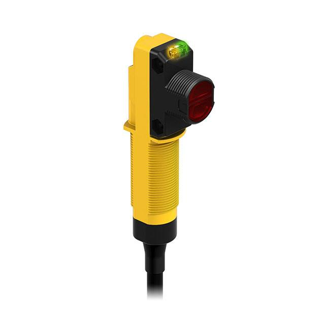
Indicators
1. Green: Power Indicator
2. Amber: Output Indicator
3. Sensitivity (Gain) Potentiometer
Wiring Diagrams
Cabled Models
Quick Disconnect (QD) Models
1 = Brown
3 = Blue
4 = Black (no connection for emitters)
1
2
3
4
=
=
=
=
Red/Black
Red/White
Red (no connection for emitters)
Green (no connection for emitters)
Emitter
Emitter
1
1
L1 (DC+)
L2 (DC–)
4
P-MOSFET
P-MOSFET
L1 (DC+)
3
2
Load
3
L2 (DC–)
4
N-MOSFET
2
L1 (DC+)
Load
L2 (DC–)
No Connection
N-MOSFET
1
1
3
No Connection
1
1
4
L2 (DC–)
3
3
4
L1 (DC+)
2
L1 (DC+)
3
2
Load
4
L2 (DC–)
www.bannerengineering.com - Tel: +1-763-544-3164
L1 (DC+)
Load
L2 (DC–)
No Connection
P/N 136003 Rev. F
�WORLD-BEAM® QS18 Universal Voltage Sensors
Specifications
Supply Voltage
P-MOSFET Models: 20 to 140 V ac/dc at less than 10 mA, exclusive of
load
N-MOSFET Models: 20 to 270 V ac/dc at less than 10 mA, exclusive of
load
Supply Protection Circuitry
Protected against reverse polarity and transient voltages
Output Configuration
Single Discrete Output, 100 mA load rating; N-MOSFET or P-MOSFET,
depending on model number; Light Operate or Dark Operate,
depending on model number
Output Rating
Rating: 100 mA with short circuit protection
Off-state leakage current: less than 400 µA
ON-state saturation voltage: P-MOSFET: 2.75 V; N-MOSFET: 2.5 V
Output Protection Circuitry
Protected against output short-circuit and false pulse on power up.
Latching short-circuit protection; reset by cycling power.
Delay at power up; outputs do not conduct during this time: 100 ms
max. dc, 300 ms max. ac
Required Overcurrent Protection
Output Response
Opposed mode: 16.6 ms (1 cycle at 60 Hz)
All other modes: 8.3 ms (1/2 cycle at 60 Hz)
Repeatability
1.5 ms
Indicators
2 LED indicators on sensor top:
Green solid: Power on
Green flashing: Sensor output short circuit
Amber solid: Light sensed
Amber flashing: Marginal excess gain (1 to 1.5x excess gain)
Adjustments
Diffuse, Retroreflective and Polarized Retroreflective models only: 1turn potentiometer Sensitivity (Gain) adjustment
Construction
ABS housing, PMMA lens, Acetal Gain Adjuster
Connections
2 m (6.5 ft) 3-conductor, 22 AWG PVC cable (300 V ac), or 150 mm (6
in) pigtail PVC cable with 4-pin threaded Micro-style connector; “C1”
suffix models: 2 m (6.5 ft) 3-conductor, 22 AWG PVC cable (600 V ac).
Environmental Rating
IEC IP67; NEMA 6; UL Type 1
1200 PSI washdown; NEMA ICS5, Annex F-2002 (PW12)
WARNING: Electrical connections must be
made by qualified personnel in accordance
with local and national electrical codes and
regulations.
Overcurrent protection is required to be provided by end product
application per the supplied table.
Overcurrent protection may be provided with external fusing or via
Current Limiting, Class 2 Power Supply.
Supply wiring leads < 24 AWG shall not be spliced.
For additional product support, go to www.bannerengineering.com.
Supply Wiring (AWG)
Required Overcurrent Protection (Amps)
20
5.0
22
3.0
24
2.0
26
1.0
28
0.8
30
0.5
Operating Conditions
Relative Humidity: 95% at 55 °C (non-condensing)
Temperature: Less than 140 V ac/dc: −25 °C to 70 °C (−13 °F to
158 °F) (N-MOSFET and P-MOSFET models)
140 V ac/dc or greater: −25 °C to 55 °C (−13 °F to 131 °F) (NMOSFET models only)
Certifications
IND. CONT. EQ.
Dimensions
10.2 mm
0.40"
7.5 mm
0.30"
5.2 mm
0.20"
17.3 mm
0.68"
80.5 mm
3.17"
3.8 mm
0.15"
24.1 mm
0.95"
5 mm
0.2"
36 mm
1.42"
M18 X 1-6g
Max. torque 2.3 Nm (20 in-lbs)
79.9 mm
3.15"
2X Ø3.3 mm
0.13"
Max. torque 0.6 Nm (5 in-lbs)
M18 X 1-6g
Max. torque 2.3 Nm (20 in-lbs)
14.5 mm
0.57"
All measurements are listed in millimeters [inches], unless noted otherwise.
P/N 136003 Rev. F
www.bannerengineering.com - Tel: +1-763-544-3164
3
�WORLD-BEAM® QS18 Universal Voltage Sensors
Packing List
Sensor
M18 × 1 jam nut
M3 hardware packet
Datasheet
24.2 mm
(0.95")
M3 Hardware Packet Contents
2 – M3 × 0.5 × 20 mm SS Screw
2 – M3 × 0.5 SS Hex Nut
2 – M3 SS Washer
8.0 mm
(0.32")
Performance Curves
Opposed Mode
Excess Gain
Beam Pattern
1000
QS186E and
QS18...R
EXCESS GAIN
Opposed Mode
QS186E and QS18...R
750 mm
100
30 in
Opposed Mode
500 mm
20 in
250 mm
10 in
0
10
0
250 mm
10 in
500 mm
20 in
750 mm
30 in
1
0.1 m
(0.3')
1m
(3.3')
0
100 m
(330')
10 m
(33')
4m
12 ft
8m
26 ft
12 m
40 ft
16 m
52 ft
20 m
66 ft
DISTANCE
DISTANCE
Polarized Retroreflective
Excess Gain
Beam Pattern
1000
QS18...LP
EXCESS GAIN
Retroreflective Mode
QS18...LP
30 mm
100
20 mm
with BRT-84 Reflector
0.4 in
with BRT-84 Reflector
0
0
0.1 m
0.33 ft
1m
3.3 ft
10 m
33 ft
10 mm
0.4 in
20 mm
0.8 in
30 mm
1.2 in
0
DISTANCE
4
0.8 in
Retroreflective Mode
10 mm
10
1
0.01 m
0.03 ft
1.2 in
.75 m
2.5 ft
1.5 m
5 ft
2.25 m
7.5 ft
3.0 m
10 ft
3.75 m
12.5 ft
DISTANCE
www.bannerengineering.com - Tel: +1-763-544-3164
P/N 136003 Rev. F
�WORLD-BEAM® QS18 Universal Voltage Sensors
Retroreflective
Excess Gain
Beam Pattern
1000
QS18...LV
EXCESS GAIN
Retroreflective Mode
QS18...LV
150 mm
100
6 in
Retroreflective Mode
100 mm
4 in
50 mm
2 in
with BRT-84 Reflector
0
10
with BRT-84 Reflector
1
0.01 m
0.03 ft
0.1 m
0.33 ft
2 in
100 mm
4 in
150 mm
6 in
0
10 m
33 ft
1m
3.3 ft
0
50 mm
1.5 m
5 ft
3.0 m
10 ft
4.5 m
15 ft
6.0 m
20 ft
7.5 m
25 ft
DISTANCE
DISTANCE
Diffuse (performance based on 90% performance white test card)
Excess Gain
Beam Pattern
1000
EXCESS GAIN
QS18A..WDL
QS18A..WDL
6 mm
100
4 mm
0.15"
2 mm
0.07"
0
10
1
1 mm
0.04"
10 mm
0.4"
100 mm
4"
0.23"
0
2 mm
0.07"
4 mm
0.15"
6 mm
0.23"
1000 mm
40"
0
DISTANCE
100 mm 200 mm 300 mm 400 mm 500 mm
(4")
(8")
(12")
(16")
(20")
DISTANCE
1000
QS18A..WDXL
QS18A..WDXL
EXCESS GAIN
15 mm
100
10 mm
0.2"
0
1
1 mm
0.04"
P/N 136003 Rev. F
0.4"
5 mm
10
10 mm
0.4"
100 mm
4"
DISTANCE
1000 mm
40"
0.6"
0
5 mm
0.2"
10 mm
0.4"
15 mm
0.6"
0
200 mm 400 mm 600 mm 800 mm 1000 mm
(8")
(16")
(24")
(32")
(40")
www.bannerengineering.com - Tel: +1-763-544-3164
DISTANCE
5
�WORLD-BEAM® QS18 Universal Voltage Sensors
Accessories
Cordsets
4-Pin Micro-Style Cordsets
Model
Length
MQAC-406
1.83 m (6 ft)
MQAC-415
4.57 m (15 ft)
Style
Dimensions
3
42 Typ.
2
Straight
MQAC-430
Pinout (Female)
1/2-20 UNF-28
ø 14.5
9.14 m (30 ft)
4
1
1 = Red/Black
2 = Red/White
3 = Red
4 = Green
Mounting Brackets
SMB18A
•
Right-angle mounting
bracket with a curved
slot for versatile
orientation
•
12-ga. stainless steel
•
18 mm sensor
mounting hole
•
Clearance for M4 (#8)
hardware
SMBQS18WRS
30
C
A
•
Retrofit bracket for
Universal voltage
models; sensor base
threads into bracket,
bracket bolts to flat
surface
•
PBT construction
•
Clearance for M3 or
#6-32 hardware
41
B
46
Hole center spacing: A to B = 24.2
Hole size: A = ø 4.6, B = 17.0 × 4.6, C = ø 18.5
Other sensor model shown with bracket above. Refer to your current Banner catalog for more mounting bracket options, including:
SMB312S, SMB18SF, SMB3018SC, SMB18FA.
Retroreflective Targets
Banner offers a wide selection of high-quality retroreflective targets. See
www.bannerengineering.com for complete information.
NOTE: Polarized sensors require corner cube type
retroreflective targets. Non-polarized sensors may use
any retroreflective target.
6
www.bannerengineering.com - Tel: +1-763-544-3164
P/N 136003 Rev. F
�WORLD-BEAM® QS18 Universal Voltage Sensors
Apertures
Model
Description
Pieces
Circular
APQS18-020
0.5 mm dia.
6
APQS18-040
1.0 mm dia.
6
APQS18-100
2.5 mm dia.
6
APQS18-020H
0.5 × 6.4 mm
6
APQS18-040H
1.0 × 6.4 mm
6
APQS18-100H
2.5 × 6.4 mm
6
APQS18-020V
0.5 × 12.7 mm
6
APQS18-040V
1.0 × 12.7 mm
6
APQS18-100V
2.5 × 12.7 mm
6
Horizontal Slot
Vertical Slot
Kit
APQS18-DVHX2
2 of each aperture
18
Banner Engineering Corp. Limited Warranty
Banner Engineering Corp. warrants its products to be free from defects in material and workmanship for one year following the date of shipment. Banner Engineering Corp.
will repair or replace, free of charge, any product of its manufacture which, at the time it is returned to the factory, is found to have been defective during the warranty
period. This warranty does not cover damage or liability for misuse, abuse, or the improper application or installation of the Banner product.
THIS LIMITED WARRANTY IS EXCLUSIVE AND IN LIEU OF ALL OTHER WARRANTIES WHETHER EXPRESS OR IMPLIED (INCLUDING, WITHOUT LIMITATION,
ANY WARRANTY OF MERCHANTABILITY OR FITNESS FOR A PARTICULAR PURPOSE), AND WHETHER ARISING UNDER COURSE OF PERFORMANCE, COURSE
OF DEALING OR TRADE USAGE.
This Warranty is exclusive and limited to repair or, at the discretion of Banner Engineering Corp., replacement. IN NO EVENT SHALL BANNER ENGINEERING CORP. BE
LIABLE TO BUYER OR ANY OTHER PERSON OR ENTITY FOR ANY EXTRA COSTS, EXPENSES, LOSSES, LOSS OF PROFITS, OR ANY INCIDENTAL,
CONSEQUENTIAL OR SPECIAL DAMAGES RESULTING FROM ANY PRODUCT DEFECT OR FROM THE USE OR INABILITY TO USE THE PRODUCT, WHETHER
ARISING IN CONTRACT OR WARRANTY, STATUTE, TORT, STRICT LIABILITY, NEGLIGENCE, OR OTHERWISE.
Banner Engineering Corp. reserves the right to change, modify or improve the design of the product without assuming any obligations or liabilities relating to any product
previously manufactured by Banner Engineering Corp. Any misuse, abuse, or improper application or installation of this product or use of the product for personal protection
applications when the product is identified as not intended for such purposes will void the product warranty. Any modifications to this product without prior express approval
by Banner Engineering Corp will void the product warranties. All specifications published in this document are subject to change; Banner reserves the right to modify product
specifications or update documentation at any time. Specifications and product information in English supersede that which is provided in any other language. For the most
recent version of any documentation, refer to: www.bannerengineering.com.
©
Banner Engineering Corp. All rights reserved
�