Photoelectrics
Through-beam, Transistor Output
Type PD70CNT12..
•
•
•
•
•
•
•
•
•
•
•
Product Description
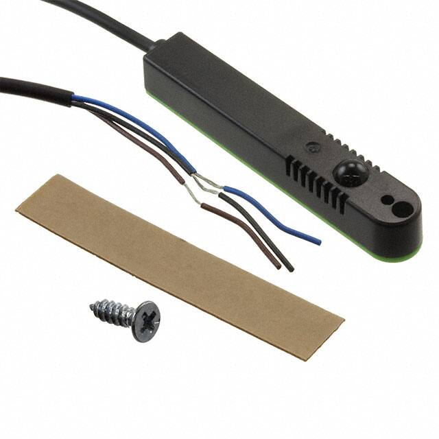
The PD70 sensor family of
Photoelectric
sensors is
specially designed for Doors
and Entrance control to
meet the requirements in the
door market. The slim housing design fits inside the alu-
Doors and Entrance control
Range 12 m
Modulated, infrared light
Supply voltage: 10 to 30 VDC
Output: 100 mA, NPN or PNP type
Make or break switching
LED for output indication or power supply
Protection: reverse polarity, short circuit, transients
Cable versions or M8 connector
Emitter mute
CE and UL325 approved
Ordering Key
minium frame of e.g. sliding
doors.
The emitter has a test input
to turn it off for evaluation of
the sensor function.
Available in 10-30 VDC
version.
PD70CNT12NOM5MH
Type
Housing style
Housing size
Housing material
Sensor code
Detection principle
Sensing distance
Output type
Output configuration
Connection type
Mute input
Type Selection
Test
Range
Sn
Connector
Ordering no.
Receiver
NPN, NO
Ordering no.
Receiver
NPN, NC
Ordering no.
Receiver
PNP, NO
Mute Low
Mute Low
Mute High
Mute High
12 m
12 m
12 m
12 m
NO
YES
NO
YES
PD70CNT12NO
PD70CNT12NOM5
PD70CNT12NC
PD70CNT12PO
PD70CNT12NCM5 PD70CNT12POM5
Ordering no.
Receiver
PNP, NC
Ordering no.
Emitter
PD70CNT12PC
PD70CNT12PCM5
PD70CNT12ML
PD70CNT12M5ML
PD70CNT12MH
PD70CNT12M5MH
Note: Please order emitter and receiver separately
Specifications Emitter
Rated operational volt. (UB)
Ripple (Urrp)
Supply current
Protection
Test input
Test High
Emitter off
Emitter on
Test Low
Emitter off
Emitter on
10 to 30 VDC
≤ 10%
≤ 20 mA
Reverse polarity, transients
Light source
Light type
Optical angle
Indication function
Power supply ON
LED, 850 nm
Infrared, modulated
< ± 5°
LED, green
5 to 30 VDC
< 2.5 VDC or not connected
< 2.5 VDC
5 to 30 VDC or not
connected
Specifications are subject to change without notice (07.06.2010)
1
�PD70
Specifications Receiver
Rated operating dist. (Sn)
Blind zone
Temperature drift
Hysteresis (H)
Rated operational volt. (UB)
Ripple (Urrp)
Output current
Continuous (Ie)
Short-time (I)
12 m
None
≤ 0.2%/°C
10 - 15%
10 to 30 VDC (ripple included)
≤ 10%
≤ 100 mA
≤ 100 mA,
(max. load capacity 100 nF)
No load supply current (Io)
≤ 16 mA
Minimum operational current (Im) 0.5 mA
Ambient light
100.000 LUX
Optical angle
OFF-state current (Ir )
Voltage drop (Ud )
Protection
± 5°
≤100 µA
≤ 1.8 VDC @ 100 mA
Short-circuit, reverse polarity, transients
Operating frequency (f)
100 Hz
Response time OFF-ON (tON) < 5 ms
ON-OFF (tOFF) < 5 ms
Power ON delay (tv )
≤ 200 ms
Output function
NPN or PNP
Make or break (NO or NC)
Indication function
Output ON
LED, yellow
General Specifications
Environment
Overvoltage category
Pollution degree
Degree of protection
Temperature
Operating
Storage
Vibration
Shock
Rated insulation voltage
Housing material
Housing
Backpart receiver
Backpart emitter
Connection
Cable
II (IEC 60664/60664A,
60947-1)
3 (IEC 60664/60664A,
60947-1)
IP 67 (IEC 60529, 60947-1)
-25° to +55°C (-13° to +131°F)
-40° to +70°C (-40° to +158°F)
10 to 150 Hz, 0.5 mm/7.5 g
(IEC 60068-2-6)
2 x 1 m & 100 x 0.5 m
(IEC 60068-2-32)
50 VDC
Plug
Weight (each sensor)
With cable
With plug
CE-marking
UL-Approval
PC black
PC Green
PC Red
PVC, TX: grey / RX: black,
5 m, 3 x 0.14 mm2, Ø 2.9 mm
M8 - 3 pole
90 g
20 g
EN12445, EN12453,
EN12978
cus UL325, CSA-C22.2 No.247
Operation Diagram
tv = Power ON delay
Power supply
Target emitter present
Object present
Break (NC) Output ON
Make (NO) Output ON
Test active High (MH)
Test active Low (ML)
Installation Hints
To avoid interference from inductive voltage/
current peaks, separate the prox. switch power cables from any other power cables, e.g.
motor, contactor or solenoid cables
Relief of cable strain
Protection of the sensing face
Switch mounted on mobile carrier
A proximity switch should not serve as
mechanical stop
Any repetitive flexing of the
cable should be avoided
Incorrect
Correct
The cable should not be pulled
2
Specifications are subject to change without notice (07.06.2010)
�PD70
Dimensions
Detection Diagram
Cable version
0,8
Plug version
11,6
Displacement (m)
0,6
11,6
11,53
11,53
10
0,4
0,2
0
-0,2
-0,4
10
-0,6
6,9
Ø4
3,3
-0,8
1
0
Ø2,5
2
3
4
5
6
7
Diastance (m)
8
9
10
11
12
70
Excess Gain
200
Excess Gain
100
10
1
1
10
20
Distance (m)
Wiring Diagram
Emitter, mute, Low
1BN
4BK
3BU
PD 70 CNT 12 ML
Delivery Contents
• PD70
• Packaging: plastic bag
Receiver
1BN
1BN
4BK
4BK
3BU
PD 70 CNT 12 NO
3BU
PD 70 CNT 12 NC
Emitter, mute, High
1BN
4BK
3BU
PD 70 CNT 12 MH
1BN
1BN
4BK
4BK
3BU
PD 70 CNT 12 PO
3BU
PD 70 CNT 12 PC
Specifications are subject to change without notice (07.06.2010)
3
�


 工商网监
湘ICP备2023018690号
工商网监
湘ICP备2023018690号
