Q45BB6 Series Sensors
Datasheet
10 V dc to 30 V dc Photoelectric Sensors With Sinking and Sourcing Solid-State Outputs
•
•
•
•
•
•
•
•
•
•
Advanced one-piece photoelectric sensors with outstanding optical performance and
extremely rugged design
Operate from: 10 V dc to 30 V dc
Bipolar NPN (sinking)/PNP (sourcing) outputs on all models
Multiple sensing modes available: opposed, diffuse, retroreflective, and convergent,
plus glass and plastic fiber optic models
Selectable light/dark operate
Versatile plug-in modules available for output timing logic and/or signal strength
display
Highly visible Power, Signal (AID™ System 1), and Output indicator LEDs
Choice of prewired 2 m (6.5 ft) or 9 m (30 ft) unterminated cable, plus Mini-style or
Euro-style quick-disconnect fittings
Versatile mounting options
Designed to withstand 1200 psi washdown; exceeds its NEMA 6P and IEC IP67 rating
WARNING: Not To Be Used for Personnel Protection
Never use this device as a sensing device for personnel protection. Doing so could lead to
serious injury or death. This device does not include the self-checking redundant circuitry necessary
to allow its use in personnel safety applications. A sensor failure or malfunction can cause either an
energized or de-energized sensor output condition.
Models
To order the 9 m (30 ft) cable models, add the suffix "W/30" to the cabled model number. Models with a quick disconnect
(QD) connector require a mating cable.
Opposed-Mode Emitter (E) and Receiver (R) Models
Because of their extremely high excess gain, these opposed-mode sensors are an excellent option
for sensing in contaminated or dirty areas, and are also the best choice for long-range sensing.
OPPOSED
Infrared, 880 nm
Models
Range
Cable
Q456E Emitter
2-wire 2 m (6.5 ft) cable
Q45BB6R Receiver
4-wire 2 m (6.5 ft) cable
Q456EQ Emitter
Q45BB6RQ Receiver
Q456EQ5 Emitter
Q45BB6RQ5 Receiver
60 m (200 ft)
4-Pin Mini-style QD
Supply Voltage
Output Type
10 V dc to 30 V dc
Bipolar NPN/PNP
4-pin Euro-style QD
1 U.S. Patent no. 4356393
Original Document
36578 Rev. E
11 November 2016
36578
�Q45BB6 Series Sensors
Retroreflective-Mode Models
The visible red sensing beam of these sensors makes them very easy to align. Model
Q45BB6LP polarizes the emitted light and filters out unwanted reflections, making
sensing possible in applications otherwise considered unsuited to retroreflective
sensing. Specified using the model BRT-3 3-inch reflector (go to
www.bannerengineering.com additional information).
P
RETRO
POLAR RETRO
Visible red, 680 nm
(non-polarized)
Visible red, 680 nm
(polarized)
Non-Polarized
Models
Range
Cable
Q45BB6LV
Q45BB6LVQ
Supply Voltage
Output Type
10 V dc to 30 V dc
Bipolar NPN/PNP
Supply Voltage
Output Type
10 V dc to 30 V dc
Bipolar NPN/PNP
4-wire 2 m (6.5 ft) cable
0.08 to 9 m (3 in to 30 ft)
Q45BB6LVQ5
4-Pin Mini-style QD
4-Pin Euro-style QD
Polarized
Models
Range
Cable
Q45BB6LP
Q45BB6LPQ
4-wire 2 m (6.5 ft) cable
0.15 to 6 m (6 in to 20 ft)
Q45BB6LPQ5
4-Pin Mini-style QD
4-Pin Euro-style QD
Diffuse-Mode Models
These diffuse-mode models detect objects by sensing the reflection of their own emitted light. Ideal for
use when the reflectivity and profile of the object to be sensed are sufficient to return a large percentage
of emitted light back to the sensor. Model Q45BB6DX is the first choice for diffuse-mode applications
when there are no background objects to falsely return light.
DIFFUSE
Infrared, 880 nm
Short Range
Models
Range
Cable
Q45BB6D
Q45BB6DQ
Supply Voltage
Output Type
10 V dc to 30 V dc
Bipolar NPN/PNP
Supply Voltage
Output Type
10 V dc to 30 V dc
Bipolar NPN/PNP
Supply Voltage
Output Type
10 V dc to 30 V dc
Bipolar NPN/PNP
4-wire 2 m (6.5 ft) cable
45 cm (18 in)
Q45BB6DQ5
4-Pin Mini-style QD
4-Pin Euro-style QD
Long Range
Models
Range
Q45BB6DL
Q45BB6DLQ
Cable
4-wire 2 m (6.5 ft) cable
1.8 m (6 ft)
Q45BB6DLQ5
4-Pin Mini-style QD
4-Pin Euro-style QD
High Power
Models
Range
Q45BB6DX
Q45BB6DXQ
Q45BB6DXQ5
2
Cable
4-wire 2 m (6.5 ft) cable
3 m (10 ft)
4-Pin Mini-style QD
4-Pin Euro-style QD
www.bannerengineering.com - Tel: +1-763-544-3164
P/N 36578 Rev. E
�Q45BB6 Series Sensors
Convergent-Mode Models
These sensors are ideal for reflective sensing of very small parts or profiles, and can accurately sense the
position of parts approaching from the side. Ignores all but highly reflective objects that are outside the
sensing range.
CONVERGENT
Visible red, 680 nm
Models
Q45BB6CV
Q45BB6CVQ
Q45BB6CVQ5
Q45BB6CV4
Q45BB6CV4Q
Q45BB6CV4Q5
Focus
Cable
38 mm (1.5 in)
4-wire 2 m (6.5 ft) cable
Spot Size at Focus:
1.3 mm (0.05 in)
4-Pin Mini-style QD
4-Pin Euro-style QD
100 mm (4 in)
4-wire 2 m (6.5 ft) cable
Spot Size at Focus:
1.5 mm (0.06 in)
4-Pin Mini-style QD
Supply Voltage
Output Type
10 V dc to 30 V dc
Bipolar NPN/PNP
10 V dc to 30 V dc
Bipolar NPN/PNP
4-Pin Euro-style QD
Glass Fiber Optic Models
These models are an excellent choice for glass fiber optic applications where faster sensor response is not
important. Their high excess gain means that opposed individual fibers can operate reliably in many very
hostile environments. Also, special miniature bifurcated fiber optic assemblies with bundle sizes as small as
0.5 mm (.020 in) diameter may be used successfully for diffuse-mode sensing when using sensor model
Q45BB6F(Q). For more information on compatible glass fiber optics, go to www.bannerengineering.com.
Range: Range varies by sensing mode and fiber optics used.
GLASS FIBER
Infrared, 880 nm and
Visible red, 650 nm
Infrared, 880 nm
Models
Q45BB6F
Cable
Supply Voltage
Output Type
10 V dc to 30 V dc
Bipolar NPN/PNP
4-wire 2 m (6.5 ft) cable
Q45BB6FQ
4-Pin Mini-style QD
Q45BB6FQ5
4-Pin Euro-style QD
Visible Red, 650 nm
Models
Q45BB6FV
Cable
Supply Voltage
Output Type
10 V dc to 30 V dc
Bipolar NPN/PNP
4-wire 2 m (6.5 ft) cable
Q45BB6FVQ
4-Pin Mini-style QD
Q45BB6FVQ5
4-Pin Euro-style QD
Plastic Fiber Optic Models
Lower in cost than glass fiber optics, plastic fiber optics are ideal for use in situations where environmental
conditions allow (for example, low levels of acids, alkalis, and solvents). Most are easily cut to length in the
field, and are available in a variety of sensing end styles. For more information on compatible plastic fiber
optics, go to www.bannerengineering.com.
Visible red, 660 nm
Range: Range varies by sensing mode and fiber optics used.
Models
Q45BB6FP
Cable
Supply Voltage
Output Type
10 V dc to 30 V dc
Bipolar NPN/PNP
4-wire 2 m (6.5 ft) cable
Q45BB6FPQ
4-Pin Mini-style QD
Q45BB6FPQ5
4-Pin Euro-style QD
P/N 36578 Rev. E
PLASTIC FIBER
www.bannerengineering.com - Tel: +1-763-544-3164
3
�Q45BB6 Series Sensors
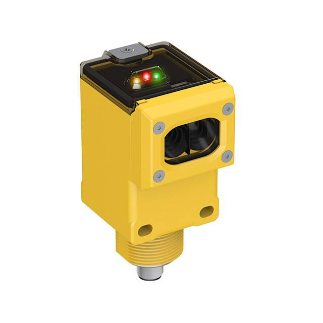
Overview
Status indicator LEDs for power, signal, and output are clearly visible beneath a raised dome in the sensor’s transparent oring-sealed polycarbonate cover. Also located beneath the sensor’s o-ring-sealed cover are controls for light/dark operate
selection and the sensitivity adjustment.
•
•
The power indicator (green) lights when power is applied to the sensor.
The signal indicator (red) lights when the sensor sees its modulated light source and pulses at a rate proportional
to the strength of the received light signal; this is the AID™ Alignment Indicating Device2.
The output indicator (amber) lights when the sensor’s output is conducting. This indicator is especially useful when
a timing logic module is used and signal and output conditions are not concurrent.
•
1. Sensitivity adjustment
2. LEDs
• Green LED: Power on indicator
• Red LED: Signal indicator
• Amber LED: Output status indicator
3. Optional LED signal strength display
4. Optional timing adjustment
5. Optional timing adjustment
6. Light/dark operate switch
6
1
5
2
3
4
Wiring Diagrams
Q45BB6 Sensors with Attached Cable
1
+
10-30V dc
–
3
2
4
Load
Q456E Emitters with Attached Cable
3
1
Load
–
Key:
1=Brown
2=White
3=Blue
4=Black
10-30V dc
+
NOTE: Wiring for quick disconnect (QD) models (model suffix Q and Q5) are functionally identical.
2 US patent no. 4356393
4
www.bannerengineering.com - Tel: +1-763-544-3164
P/N 36578 Rev. E
�Q45BB6 Series Sensors
Specifications
Supply Voltage and Current
10 V dc to 30V dc (10% maximum ripple), at less than 50 mA
(exclusive of load)
Supply Protection Circuitry
Protected against reverse polarity and transient voltages
Output Configuration
Bipolar: one current sourcing (PNP) and one current sinking (NPN)
open-collector transistor
Output Rating
250 mA maximum each output up to 50 °C, derated to 150 mA at
70 °C (derates 5 mA/°C)
Off-state leakage current less than 1 µA
Output saturation voltage (both outputs) less than 1 V at 10 mA and
less than 2 V at 250 mA
Output Protection Circuitry
Protected against false pulse on power-up and continuous overload or
short circuit of outputs
Output Response Time
Opposed mode: 2 milliseconds ON, 1 millisecond OFF
All other sensing modes: 2 milliseconds ON/OFF
NOTE: 100 millisecond delay on power-up.
Output is non-conducting during this time.
Repeatability
Opposed mode: 0.25 milliseconds
All other sensing modes: 0.5 milliseconds
Response time and repeatability specifications are independent of
signal strength.
Indicators
Indicator LEDs are clearly visible beneath a raised transparent Lexan®
dome on top of the sensor.
Power (green) LED lights whenever 10 V dc to 30V dc power is applied,
and flashes to indicate output overload or output short circuit
Signal (red) AID™ System LED lights whenever the sensor sees its
modulated light source, and pulses at a rate proportional to the
strength of the received light signal
Load (amber) LED lights whenever the output is energized
Optional 7-element LED signal strength display modules
Construction
Molded reinforced thermoplastic polyester housing, o-ring-sealed
transparent Lexan®3 cover, molded acrylic lenses, and stainless steel
hardware. Designed to withstand 1200 psi washdown. The base of the
cabled models has a ½-inch NPS integral internal conduit thread.
Environmental Rating
NEMA 6, IEC IP67
Connections
PVC-jacketed 2 m (6.5 ft) or 9 m (30 ft) cables; or 4-pin Mini-style
(“Q” suffix models) or 4-pin Euro-style (“Q5” suffix models) quickdisconnect (QD) fittings are available. QD cables are ordered
separately.
Operating Conditions
Temperature: −40 °C to +70 °C (−40 °F to +158 °F)
90% at +50 °C maximum relative humidity (non-condensing)
Application Notes
Optional output timing modules are available. See Output Timing Logic
and Signal Strength Display Modules on page 9.
Certifications
Adjustments
Beneath sensor’s transparent cover: Light/Dark Operate select switch
and multi-turn Sensitivity control (allows precise sensitivity setting –
turn clockwise to increase gain). Optional logic and logic/display
modules have adjustable timing functions (see Output Timing Logic and
Signal Strength Display Modules on page 9)
Dimensions
Opposed, Retro, and Diffuse Sensing Modes (Model Suffix E, R, D, DL, DX, LP, and LV)
Cabled Models
Mini-Style Quick-Disconnect
Models
Euro-Style Quick Disconnect
Models
54.1 mm
(2.13")
44.5 mm
(1.75")
Lens Centerline
50.8 mm
(2.00")
69.0 mm
(2.72")
6.4 mm (0.25")
87.6 mm
(3.45")
4.5 mm (#10) Screw
Clearance (2)
7.1 mm
(0.28")
30.0 mm
(1.18")
Internal Thread
(1/2–14NPSM)
External thread (M30 x 1.5)
hex nut supplied
ø 6.1 (0.24")
2m (6.5') Cable
External Thread
M30 X 1.5
14 mm (0.6")
Mini-style QD Connector
15 mm (0.6")
Euro-style
QD Connector
3 Lexan® is a registered trademark of General Electric Co.
P/N 36578 Rev. E
www.bannerengineering.com - Tel: +1-763-544-3164
5
�Q45BB6 Series Sensors
Convergent Sensor Models
Glass Fiber Optic Models
Plastic Fiber Optic Models
(CV and CV4)
(F and FV)
(FP)
60.5 mm
(2.38")
61.7 mm
(2.43")
59.9 mm
(2.36")
Performance Curves
Opposed
Excess Gain
Beam Pattern
1000
Effective Beam: 13 mm
Q45E/R
E
X
C
E
S
S
Opposed Mode
G
A
I
N
Q45E/R
1.5 m
100
60 in
Opposed Mode
1.0 m
40 in
0.5 m
20 in
0
10
0
0.5 m
20 in
1.0 m
40 in
1.5 m
1
0.1 m
0.33 ft
1.0 m
3.3 ft
10 m
33 ft
100 m
330 ft
60 in
0
12 m
40 ft
24 m
80 ft
DISTANCE
Excess Gain
G
A
I
N
Beam Pattern
Retroreflective Mode
Q45LV
75 mm
Retroreflective Mode
With BRT-3 Reflector
.10 m
.33 ft
1.0 m
3.3 ft
DISTANCE
10 m
33 ft
3.0 in
50 mm
2.0 in
25 mm
1.0 in
0
10
1
.01 m
.033 ft
Excess Gain
Q45LV
100
60 m
200 ft
Retroreflective Polarized
1000
1000
48 m
160 ft
DISTANCE
Retroreflective Non-Polarized
E
X
C
E
S
S
36 m
120 ft
0
With BRT-3 Reflector
25 mm
1.0 in
50 mm
2.0 in
75 mm
3.0 in
0
3m
10 ft
6m
20 ft
9m
30 ft
DISTANCE
12 m
40 ft
15 m
50 ft
E
X
C
E
S
S
G
A
I
N
Beam Pattern
Q45LP
Retroreflective Mode
100
Q45LP
75 mm
Retroreflective
Mode
50 mm
25 mm
10
0
With BRT-3 Reflector
25 mm
1.0 in
50 mm
2.0 in
75 mm
1
.01 m
.033 ft
.10 m
.33 ft
1.0 m
3.3 ft
DISTANCE
10 m
33 ft
2.0 in
1.0 in
0
With BRT-3 Reflector
3.0 in
3.0 in
0
1.5 m
5 ft
3m
10 ft
4.5 m
15 ft
6m
20 ft
7.5 m
25 ft
DISTANCE
Diffuse-mode performance curves are based on a 90% reflectance white test card.
6
www.bannerengineering.com - Tel: +1-763-544-3164
P/N 36578 Rev. E
�Q45BB6 Series Sensors
Diffuse Short Range
Excess Gain
Diffuse Long Range
Beam Pattern
Excess Gain
1000
1000
Q45D
E
X
C
E
S
S
Diffuse Mode
15 mm
100
0.6 in
Q45D
10 mm
0.4 in
Diffuse Mode
5 mm
G
A
I
N
0.2 in
0
10
0
5 mm
0.2 in
10 mm
0.4 in
15 mm
1
1.0 mm
0.04 in
10 mm
0.4 in
100 mm
4.0 in
1000 mm
40 in
0.6 in
0
100 mm
4.0 in
200mm
8.0 in
DISTANCE
300 mm
12.0 in
E
X
C
E
S
S
G
A
I
N
Q45DL
Diffuse Mode
100
Q45DL
Diffuse Mode
75 mm
3.0 in
50 mm
2.0 in
25 mm
1.0 in
10
0
0
25 mm
1.0 in
50 mm
2.0 in
75 mm
1
.01 m
.033 ft
400 mm 500 mm
16.0 in 20.0 in
Beam Pattern
.10 m
.33 ft
DISTANCE
1.0 m
3.3 ft
10 m
33 ft
3.0 in
0
0.6 m
2 ft
1.2 m
4 ft
DISTANCE
1.8 m
6 ft
2.4 m
8 ft
3.0 m
10 ft
DISTANCE
Diffuse High Power
Excess Gain
Beam Pattern
1000
Q45DX
E
X
C
E
S
S
Diffuse Mode
100
G
A
I
N
Q45DX
75 mm
3.0 in
Diffuse Mode
50 mm
2.0 in
25 mm
1.0 in
10
0
0
25 mm
1.0 in
50 mm
2.0 in
75 mm
1
0.01 m
0.033 ft
0.1 m
0.33 ft
1.0 m
3.3 ft
10 m
33 ft
3.0 in
0
0.6 m
2 ft
DISTANCE
1.2 m
4 ft
1.8 m
6 ft
2.4 m
8 ft
3.0 m
10 ft
DISTANCE
Convergent mode performance curves are based on a 90% reflectance white test card.
Convergent (CV and CVQ Models)
Excess Gain
Convergent (CV4 and CV4Q Models)
Beam Pattern
Excess Gain
1000
1000
Q45CV
E
X
C
E
S
S
Convergent Mode
100
Q45CV
3.8 mm
0.15 in
Convergent Mode
2.5 mm
0.10 in
1.2 mm
G
A
I
N
10
0.05 in
0
1
1 mm
.04 in
10 mm
.4 in
100 mm
4 in
Beam Pattern
1000 mm
40 in
0
1.2 mm
0.05 in
2.5 mm
0.10 in
3.8 mm
0.15 in
0
38 mm
1.5 in
DISTANCE
75 mm
3.0 in
113 mm
4.5 in
E
X
C
E
S
S
G
A
I
N
Q45CV4
Convergent Mode
100
0.15 in
Convergent Mode
2.5 mm
0.10 in
1.2 mm
0.05 in
0
10
0
1.2 mm
0.05 in
2.5 mm
0.10 in
3.8 mm
1
1 mm
.04 in
150 mm 190 mm
6.0 in
7.5 in
Q45CV4
3.8 mm
10 mm
.4 in
100 mm
4 in
1000 mm
40 in
0.15 in
0
38 mm
1.5 in
113 mm
4.5 in
150 mm 190 mm
6.0 in
7.5 in
DISTANCE
DISTANCE
DISTANCE
75 mm
3.0 in
Glass fiber optic diffuse mode performance curves are based on a 90% reflectance white test card.
Glass Fiber Optic, Infrared (Opposed Mode)
Excess Gain
Glass Fiber Optic, Infrared (Diffuse Mode)
Beam Pattern
Excess Gain
1000
E
X
C
E
S
S
G
A
I
N
1000
Q45F
Opposed Mode
100
Q45F
150 mm
IT23S Fibers
50 mm
10
0
IT13S Fibers
0.1 m
0.33 ft
1.0 m
3.3 ft
DISTANCE
P/N 36578 Rev. E
10 m
33 ft
6.0 in
Opposed Mode
100 mm
IT23S Fibers
1
0.01 m
0.03 ft
Beam Pattern
4.0 in
2.0 in
0
IT13S Fibers
50 mm
2.0 in
100 mm
4.0 in
150 mm
6.0 in
0
0.4 m
15 in
0.8 m
30 in
1.2 m
45 in
DISTANCE
1.6 m
60 in
2.0 m
75 in
E
X
C
E
S
S
G
A
I
N
Q45F
Diffuse Mode
100
Q45F
3.8 mm
Diffuse Mode
2.5 mm
BT13S Fiber
1.3 mm
BT23S Fiber
BT13S Fiber
10 mm
0.4 in
100 mm
4.0 in
DISTANCE
www.bannerengineering.com - Tel: +1-763-544-3164
1000 mm
40 in
0
1.3 mm
0.05 in
2.5 mm
0.10 in
3.8 mm
1
1 mm
0.04 in
0.10 in
0.05 in
BT23S Fiber
0
10
0.15 in
0.15 in
0
25 mm
1 in
50 mm
2 in
75 mm
3 in
100 mm 125 mm
4 in
5 in
DISTANCE
7
�Q45BB6 Series Sensors
Glass Fiber Optic, Visible Red (Opposed Mode)
Excess Gain
Glass Fiber Optic, Visible Red (Diffuse Mode)
Beam Pattern
Excess Gain
1000
1000
E
X
C
E
S
S
G
A
I
N
Beam Pattern
Q45FV
Opposed Mode
Q45FV
30 mm
100
Opposed Mode
20 mm
IT23S Fibers
10 mm
0.4 in
0
10
1
1.0 mm
0.04 in
10 mm
0.4 in
0
10 mm
IT13S Fibers
100 mm
4 in
1.2 in
0.8 in
IT23S Fibers
0.4 in
IT13S Fibers
20 mm
0.8 in
30 mm
1.2 in
0
1000 mm
40 in
100 mm
4 in
150 mm
6 in
200 mm
8 in
E
X
C
E
S
S
G
A
I
N
Q45FV
Diffuse Mode
100
0.08 in
1.0 mm
10
0.04 in
BT13S Fiber
0
BT13S
Fiber
0
1.0 mm
BT23S Fiber
0.04 in
BT23S Fiber
2.0 mm
0.08 in
3.0 mm
10 mm
0.4 in
100 mm
4.0 in
1000 mm
40 in
0.12 in
0
5 mm
0.2 in
10 mm
0.4 in
DISTANCE
DISTANCE
DISTANCE
0.12 in
Diffuse Mode
2.0 mm
1
1 mm
0.04 in
250 mm 300 mm
10 in
12 in
Q45FV
3.0 mm
15 mm
0.6 in
20 mm
0.8 in
25 mm
1.0 in
DISTANCE
Plastic fiber optic Diffuse mode performance curves are based on a 90% reflectance white test card.
Plastic Fiber Optic (Diffuse Mode)
Plastic Fiber Optic (Opposed Mode)
Excess Gain
Beam Pattern
Excess Gain
1000
E
X
C
E
S
S
1000
Q45FP
Opposed Mode
100
Q45FP
45 mm
0
PIT26U Fibers
100 mm
4.0 in
1.2 in
0.6 in
0
PIT26U Fibers
15 mm
10 mm
0.4 in
PIT46U Fibers
15 mm
10
1
1 mm
0.04 in
1.8 in
Opposed Mode
30 mm
PIT46U Fibers
G
A
I
N
Beam Pattern
0.6 in
30 mm
1.2 in
45 mm
1.8 in
1000 mm
40 in
0
DISTANCE
25 mm
1.0 in
50 mm
2.0 in
75 mm
3.0 in
100 mm 125 mm
4.0 in
5.0 in
DISTANCE
E
X
C
E
S
S
G
A
I
N
Q45FP
Diffuse Mode
100
PBT46U Fiber
Q45FP
18 mm
0.75 in
Diffuse Mode
12 mm
0.50 in
PBT46U Fiber
6 mm
0.25 in
0
10
0
6 mm
PBT26U Fiber
1
0.1 mm
0.004 in
1 mm
0.04 in
10 mm
0.4 in
100 mm
4 in
0.25 in
12 mm
0.50 in
18 mm
0.75 in
0
10 mm
0.4 in
20 mm
0.8 in
DISTANCE
30 mm
1.2 in
40 mm
1.6 in
50 mm
2.0 in
DISTANCE
Accessories
Corsets
4-Pin Threaded M12/Euro-Style Cordsets
Model
Length
MQDC-406
1.83 m (6 ft)
MQDC-415
4.57 m (15 ft)
MQDC-430
Style
Dimensions
Pinout (Female)
9.14 m (30 ft)
3
4
Straight
MQDC-450
2
1
44 Typ.
M12 x 1
ø 14.5
15.2 m (50 ft)
1 = Brown
2 = White
3 = Blue
4 = Black
4-Pin Mini-Style Cordsets
Model
Length
MBCC-406
1.83 m (6 ft)
MBCC-412
3.66 m (12 ft)
Style
Dimensions
52 Typ.
Pinout (Female)
7/8-16UN-2B
Straight
MBCC-430
8
ø 25.5
9.14 m (30 ft)
www.bannerengineering.com - Tel: +1-763-544-3164
2
4
1
3
1
2
3
4
=
=
=
=
Brown
White
Blue
Black
P/N 36578 Rev. E
�Q45BB6 Series Sensors
Retroreflective Targets
Banner offers a wide selection of high-quality retroreflective targets. See
www.bannerengineering.com for complete information.
NOTE: Polarized sensors require corner cube type
retroreflective targets. Non-polarized sensors may use
any retroreflective target.
Brackets
SMB30C
•
56
SMB30MM
30 mm split clamp, black
A
PBT bracket
•
•
•
B
Mounting hole for 30 mm
sensor
13
Hole center spacing: A=ø 45
Hole size: B=ø 27.2
•
Clearance for M6 (¼ in)
hardware
•
Mounting hole for 30 mm
sensor
57
70
with curved mounting slots
for versatile orientation
66
Stainless steel mounting
hardware included
12-ga. stainless steel bracket
C
57
B
A
Hole center spacing: A = 51, A to B = 25.4
Hole size: A = 42.6 x 7, B = ø 6.4, C = ø 30.1
SMB30SC
•
Swivel bracket with 30 mm
mounting hole for sensor
•
Black reinforced
thermoplastic polyester
•
Stainless steel mounting and
swivel locking hardware
included
67
B
58
29
A
Hole center spacing: A=ø 50.8
Hole size: A=ø 7.0, B=ø 30.0
Output Timing Logic and Signal Strength Display Modules
Q45 sensors easily accept the addition of output timing logic and signal strength display functions. Display modules have a
seven-element display that gives a more precise indication of excess gain than does the AID™ system LED that is standard
on Q45 sensors. The modules listed below may be used with all Q45BB6 sensors. Refer to the module's datasheet for more
information.
Models
Logic and/or Display Function
45LM58
Programmable output timing logic
45LM58D
Programmable output timing logic plus signal strength display
45LMD
Signal strength display only (no timing function)
P/N 36578 Rev. E
www.bannerengineering.com - Tel: +1-763-544-3164
9
�Q45BB6 Series Sensors
Banner Engineering Corp. Limited Warranty
Banner Engineering Corp. warrants its products to be free from defects in material and workmanship for one year following the date of shipment. Banner Engineering Corp.
will repair or replace, free of charge, any product of its manufacture which, at the time it is returned to the factory, is found to have been defective during the warranty
period. This warranty does not cover damage or liability for misuse, abuse, or the improper application or installation of the Banner product.
THIS LIMITED WARRANTY IS EXCLUSIVE AND IN LIEU OF ALL OTHER WARRANTIES WHETHER EXPRESS OR IMPLIED (INCLUDING, WITHOUT LIMITATION,
ANY WARRANTY OF MERCHANTABILITY OR FITNESS FOR A PARTICULAR PURPOSE), AND WHETHER ARISING UNDER COURSE OF PERFORMANCE, COURSE
OF DEALING OR TRADE USAGE.
This Warranty is exclusive and limited to repair or, at the discretion of Banner Engineering Corp., replacement. IN NO EVENT SHALL BANNER ENGINEERING CORP. BE
LIABLE TO BUYER OR ANY OTHER PERSON OR ENTITY FOR ANY EXTRA COSTS, EXPENSES, LOSSES, LOSS OF PROFITS, OR ANY INCIDENTAL,
CONSEQUENTIAL OR SPECIAL DAMAGES RESULTING FROM ANY PRODUCT DEFECT OR FROM THE USE OR INABILITY TO USE THE PRODUCT, WHETHER
ARISING IN CONTRACT OR WARRANTY, STATUTE, TORT, STRICT LIABILITY, NEGLIGENCE, OR OTHERWISE.
Banner Engineering Corp. reserves the right to change, modify or improve the design of the product without assuming any obligations or liabilities relating to any product
previously manufactured by Banner Engineering Corp. Any misuse, abuse, or improper application or installation of this product or use of the product for personal protection
applications when the product is identified as not intended for such purposes will void the product warranty. Any modifications to this product without prior express approval
by Banner Engineering Corp will void the product warranties. All specifications published in this document are subject to change; Banner reserves the right to modify product
specifications or update documentation at any time. Specifications and product information in English supersede that which is provided in any other language. For the most
recent version of any documentation, refer to: www.bannerengineering.com.
©
Banner Engineering Corp. All rights reserved
�