VS1 Series Sensors
Datasheet
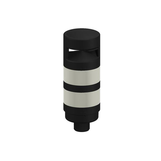
Self-contained Miniature Sensors
•
•
•
•
•
•
10 V to 30 V dc operation
Visible red or infrared sensing beam, depending on model
10 mm (0.4 in) or 15 mm (0.6 in) convergent point, depending on model
NPN (sinking) or PNP (sourcing) output, and dark or light operate,
depending on model
3-wire connection; output load capacity to 50 mA
Choice of integral cable or quick-disconnect connector
WARNING: Not To Be Used for Personnel Protection
Never use this device as a sensing device for personnel
protection. Doing so could lead to serious injury or
death. This device does not include the self-checking
redundant circuitry necessary to allow its use in personnel
safety applications. A sensor failure or malfunction can cause
either an energized or de-energized sensor output condition.
1. Power ON Indicator
2. Received Signal Indicator
3. 2 m Cable or 150 mm (6 inch)
Quick-Disconnect
Visible Red (860 nm) Beam
Models
Infrared (865 nm) Beam
Models
Focus
CONVERGENT
VISIBLE RED
Output Type
Cable1
CONVERGENT
VS1AN5CV10
VS1AN5C10
NPN/LO
VS1RN5CV10
VS1RN5C10
NPN/DO
VS1AP5CV10
VS1AP5C10
VS1RP5CV10
VS1RP5C10
PNP/DO
VS1AN5CV20
VS1AN5C20
NPN/LO
VS1RN5CV20
VS1RN5C20
VS1AP5CV20
VS1AP5C20
VS1RP5CV20
VS1RP5C20
10 mm (0.4 in)
15 mm (0.6 in)
PNP/LO
2 m (6.5 ft)
NPN/DO
PNP/LO
PNP/DO
Overview
VS1 Series miniature self-contained sensors are designed for precision sensing in small areas previously accessible only to
remote or fiber optic models. Typical applications include mounting inside vibrating feeders and electronic component
handling equipment, where larger sensors will not fit.
The sensing energy of a convergent-mode sensor is concentrated at the specified focus point. Convergent-mode sensors
are less sensitive to background reflections, compared with diffuse-mode sensors. Contact the factory if background
reflections are a problem.
1
•
•
To order 9 m cables models, add suffix “W/30” to the model number (e.g., VS1AN5CV10 W/30).
To order 150 mm (6 inch) cable with threaded 3-pin Pico-style quick disconnect fitting models, add suffix “Q” to the
model number (e.g., VS1AN5CV10Q). A model with a QD connector requires a mating cable; see Accessories on page
4.
Original Document
56465 Rev. E
18 November 2016
56465
�VS1 Series Sensors
Installation Notes
Included with each sensor is a hardware packet containing two stainless steel M2 × 0.4 × 16 mm Phillips pan-head
machine screws, flat washers, lock washers, and hex nuts. To mount the sensor, use the supplied flat washer against the
front surface of the sensor housing, between it and the screw head. If mounting to one of the optional brackets, place the
lock washer against the back of the bracket, followed by the nut. If mounting directly to a threaded hole, place the lock
washer between the screw head and the flat washer.
For best results, mount the VS1 where it is protected from moisture, high humidity and dirt.
1.
2.
3.
4.
Hex Nut (2)
Lock Washer (2)
Washer (2)
M2 × 0.4 × 16 mm Phillips Pan-head Machine Screw (2)
1
2
3
4
Wiring Diagrams
NPN Outputs
3
–
10-30 V dc
+
1
4
PNP Outputs
Load
1
+
10-30 V dc
–
3
4
Key:
1
3
4
X
=
=
=
=
Brown
Blue
Black
Load
Load
NOTE: QD hookups are shown. Cabled hookups are functionally identical.
2
www.bannerengineering.com - Tel: +1-763-544-3164
P/N 56465 Rev. E
�VS1 Series Sensors
Specifications
Supply Voltage and Current
10 V to 30 V dc (10% maximum ripple) at less than 25 mA (exclusive
of load)
Supply Protection Circuitry
Protected against reverse polarity and transient voltages
Output Protection Circuitry
Protected against false pulse on power-up and continuous overload or
short circuit of outputs. Overload trip point ≥ 100 mA.
Output Configuration
SPST solid-state switch
NPN (current sinking) or PNP (current sourcing), depending on model
Light operate (N.O.) or dark operate (N.C.), depending on model
Output Rating
50 mA maximum
OFF-state leakage current: < 1 microamp at 24 V dc
ON-state saturation voltage: < 0.25 V at 10 mA dc; < 0.5 V at 50 mA
dc
Indicators
Green ON: sensor power ON
Green flashing: output overload
Amber ON: light is sensed
Amber flashing: marginal excess gain (1 to 1.5 times) in light condition
Construction
Black ABS/polycarbonate housing with clear acrylic lens
Environmental Rating
IEC IP54; NEMA 3
Connections
2 m (6.5 ft) attached cable: three #28 ga stranded conductors with PE
insulation; PVC outer cable jacket; or
150 mm (6 inch) cable with 3-pin Pico-style quick-disconnect fitting.
QD cables are ordered separately.
Operating Conditions
−20 °C to +55 °C (−4 °F to +131°F)
80% at +50 °C maximum relative humidity (non-condensing)
Application Notes
M2 stainless steel mounting hardware included (see Installation Notes).
Optional mounting brackets are
available (see Accessories list).
Output Response Time
1 millisecond ON and OFF
Repeatability
250 microseconds
Certifications
Performance Curves
Table 1: Visible Red Beam Models2
Excess Gain
VS1...CV10
Beam Pattern
1000
E
X
C
E
S
S
G
A
I
N
VS1 Series Visible Red
10 mm Convergent Mode
100
VS1 Series Visible Red
3 mm
0.08"
1 mm
0.04"
0
10
0
1 mm
0.04"
2 mm
0.08"
3 mm
1
1 mm
0.04"
10 mm
0.4"
100 mm
4.0"
0.12"
0
1000 mm
40.0"
4 mm
0.16"
1000
E
X
C
E
S
S
G
A
I
N
VS1 Series Visible Red
20 mm Convergent Mode
100
8 mm
0.31"
12 mm
0.47"
16 mm
0.63"
VS1 Series Visible Red
20 mm Convergent Mode
6 mm
0.24"
4 mm
0.16"
2 mm
0.08"
0
10
0
2 mm
0.08"
4 mm
0.16"
6 mm
1
1 mm
0.04"
10 mm
0.4"
100 mm
4.0"
1000 mm
40.0"
DISTANCE
20 mm
0.79"
DISTANCE
DISTANCE
VS1...CV20
0.12"
10 mm Convergent Mode
2 mm
0.24"
0
10 mm
0.4"
20 mm
0.80"
30 mm
1.20"
40 mm
1.60"
50 mm
2.00"
DISTANCE
2 Performance based on 90% reflectance white card test
P/N 56465 Rev. E
www.bannerengineering.com - Tel: +1-763-544-3164
3
�VS1 Series Sensors
Table 2: Infrared Beam Models2
Excess Gain
Beam Pattern
1000
VS1...C10
E
X
C
E
S
S
G
A
I
N
VS1 Series Infrared
10 mm Convergent Mode
100
3 mm
0.12"
2 mm
0.08"
1 mm
0.04"
0
1 mm
10
10 mm
0.4"
100 mm
4.0"
0.04"
10 mm Convergent Mode
2 mm
0.08"
3 mm
0.12"
0
1
1 mm
0.04"
0
VS1 Series Infrared
1000 mm
40"
4 mm
0.16"
8 mm
0.31"
12 mm
0.47"
16 mm
0.63"
20 mm
0.79"
DISTANCE
DISTANCE
1000
VS1...C20
E
X
C
E
S
S
G
A
I
N
VS1 Series Infrared
20 mm Convergent Mode
100
6 mm
0.24"
4 mm
0.16"
2 mm
0.08"
VS1 Series Infrared
0
0
20 mm Convergent Mode
2 mm
10
0.08"
4 mm
0.16"
6 mm
1
1 mm
0.04"
10 mm
0.4"
100 mm
4.0"
0.24"
0
1000 mm
40"
10 mm
0.40"
20 mm
0.80"
30 mm
1.20"
40 mm
1.60"
50 mm
2.00"
DISTANCE
DISTANCE
Dimensions
25.7 mm
(1.01")
1
15 mm
(0.59")
13.5 mm
(0.53")
8.3 mm
(0.33")
4.1 mm
(0.16")
9.2 mm
(0.36") 11.6 mm
(0.46")
Ø2.2 mm
(0.09")
1. 150 mm (6 in) Cable
Accessories
3-Pin Threaded M8/Pico-Style Cordsets
Model
Length
PKG3M-2
2 m (6.56 ft)
PKG3M-5
5 m (16.40 ft)
PKG3M-7
7 m (22.97 ft)
PKG3M-9
PKG3M-10
4
Style
Dimensions
Pinout (Female)
4
35 Typ.
Straight
9 m (29.53 ft)
ø 9.5
M8 x 1
10 m (32.81 ft)
www.bannerengineering.com - Tel: +1-763-544-3164
1
3
1 = Brown
3 = Blue
4 = Black
P/N 56465 Rev. E
�VS1 Series Sensors
Brackets
SMBVS1T
•
Tall right-angle bracket
•
Stainless steel
32
Hole center spacing: A = 16.8
Hole size: A = 3.5 x 12.3
A
A
Hole size: A = ø 2.8
10 9
22
SMBVS1S
•
Short right-angle bracket
•
18-ga. stainless steel
Hole size: A = 3.5 x 12.3
32
Hole center spacing: A = 5.5
25
Hole center spacing: A = 16.8
SMBVS1TC
•
Tall right-angle compact
bracket
•
300 stainless steel
12
SMBVS1SC
•
Short right-angle bracket
•
18-ga. stainless steel
Hole center spacing: A = 10.0
A
11
A
Hole size: A = ø 2.8
25
22
19.5
9
Banner Engineering Corp. Limited Warranty
Banner Engineering Corp. warrants its products to be free from defects in material and workmanship for one year following the date of shipment. Banner Engineering Corp.
will repair or replace, free of charge, any product of its manufacture which, at the time it is returned to the factory, is found to have been defective during the warranty
period. This warranty does not cover damage or liability for misuse, abuse, or the improper application or installation of the Banner product.
THIS LIMITED WARRANTY IS EXCLUSIVE AND IN LIEU OF ALL OTHER WARRANTIES WHETHER EXPRESS OR IMPLIED (INCLUDING, WITHOUT LIMITATION,
ANY WARRANTY OF MERCHANTABILITY OR FITNESS FOR A PARTICULAR PURPOSE), AND WHETHER ARISING UNDER COURSE OF PERFORMANCE, COURSE
OF DEALING OR TRADE USAGE.
This Warranty is exclusive and limited to repair or, at the discretion of Banner Engineering Corp., replacement. IN NO EVENT SHALL BANNER ENGINEERING CORP. BE
LIABLE TO BUYER OR ANY OTHER PERSON OR ENTITY FOR ANY EXTRA COSTS, EXPENSES, LOSSES, LOSS OF PROFITS, OR ANY INCIDENTAL,
CONSEQUENTIAL OR SPECIAL DAMAGES RESULTING FROM ANY PRODUCT DEFECT OR FROM THE USE OR INABILITY TO USE THE PRODUCT, WHETHER
ARISING IN CONTRACT OR WARRANTY, STATUTE, TORT, STRICT LIABILITY, NEGLIGENCE, OR OTHERWISE.
Banner Engineering Corp. reserves the right to change, modify or improve the design of the product without assuming any obligations or liabilities relating to any product
previously manufactured by Banner Engineering Corp.
Copyright Notice
Any misuse, abuse, or improper application or installation of this product or use of the product for personal protection applications when the product is identified as not
intended for such purposes will void the product warranty. Any modifications to this product without prior express approval by Banner Engineering Corp will void the product
warranties. All specifications published in this document are subject to change; Banner reserves the right to modify product specifications or update documentation at any
time. For the most recent version of any documentation, refer to: www.bannerengineering.com. © Banner Engineering Corp. All rights reserved.
©
Banner Engineering Corp. All rights reserved
�