Photoelectrics
Through-beam
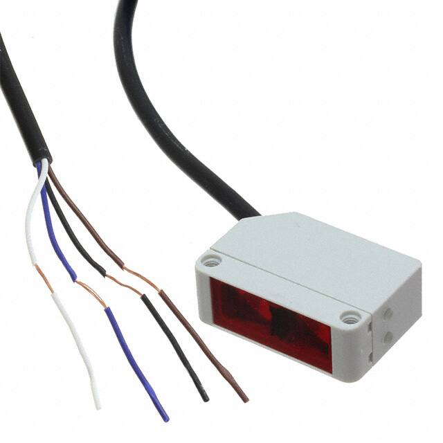
Type PD30CNT15....MU/DU
• Miniature sensor range
• Range: 15 m
• Sensitivity adjustment by Teach-In programming
• Modulated, Infraredred light 880 nm
• Supply voltage: 10 to 30 VDC
• Output: 100 mA, NPN or PNP preset
• Make and break switching function programmable
• LED indication for output, stability and power ON
• Protection: reverse polarity, short circuit and transients
• Cable and plug versions
• Excellent EMC performance
• Mute function (Sensor blanking) Emitter
• Dust alarm output - Receiver
Product Description
Ordering Key
The PD30CNT15 sensor
family comes in a compact
10 x 30 x 20 mm reinforced
PMMA/ABS housing.
The sensors are useful in
applications where high-accuracy detection as well as
small size is required.
Compact housing and high
power LED for excellent performance-size ratio.
The Teach-In function for
adjustment of the sensitivi-
Type
Housing style
Housing size
Housing material
Housing length
Detection principle
Sensing distance
Output type
Output configuration
Connection type
Dust
ty makes the sensors highly
flexible. The output type is
preset (NPN or PNP), and
the output switching function
is programmable (NO or NC),
and one dust output NO or
NC.
The mute function can be
used for testing the sensor
for: Malfunctioning, disconnection, optical axis adjustment, dusty and dirty lenses.
PD30CNT15NPM5DU
Type Selection
Housing
Range Connection Ordering no.
WxHxD
Sn
NPN
Emitter
10 x 30 x 20 mm 15 m Cable
10 x 30 x 20 mm 15 m Plug
Ordering no.
Ordering no.
NPN
PNP
Make or break switching Emitter
PD 30 CNT 15 NMU
PD 30 CNT 15 NPDU
PD 30 CNT 15 NM5MU PD 30 CNT 15 NPM5DU
Ordering no.
PNP
Make or break switching
PD 30 CNT 15 PMU
PD 30 CNT 15 PPDU
PD 30 CNT 15 PM5MU PD 30 CNT 15 PPM5DU
Note: Emitter, Receiver and Connector to be ordered separately.
Specifications Emitter
Rated operational volt. (UB )
Ripple (Urpp )
Supply current
Light Source
Optical angle
Light type
Light spot
EN 60947-5-2
10 to 30 VDC
≤ 10%
≤ 25 mA
GaAIAs, LED, 880 nm
± 2º at ½ range
Infrared, modulated
110 mm @ 1.5 m
Specifications Receiver
Protection
Reverse polarity, transients
Indication function
Power supply ON
LED, green
Mute function
Emitter off
0 to 3 sec
0 to 2.5 VDC (NPN)
5 to 30 VDC (PNP)
Emitter half power > 3 sec
0 to 2.5 VDC (NPN)
5 to 30 VDC (PNP)
EN 60947-5-2
Rated operating distance (Sn) 15 m, with PD30CNT15
Emitter
Blind zone
None
Sensitivity
Adjustable by Teach-In
Temperature drift
≤ 0.3%/ºC
Hysteresis (H)
(differential travel)
≤ 10%
Rated operational volt. (UB )
10 to 30 VDC
Ripple (Urpp )
≤ 10%
Adjustable range
1.5 m to 15 m
resolution 3% on distance
Specifications are subject to change without notice (24.08.2016)
Output current
Continuous (Ie)
Short-time (I)
Dust output current
Continuous (Ie)
Short-time (I)
No load supply current (Io)
Minimum operational current (Im)
OFF-state current (Ir )
≤ 100 mA
≤ 100 mA
(max. load capacity 100 nF)
≤ 20 mA
≤ 20 mA
(max. load capacity 100 nF)
≤ 30 mA
0.5 mA
≤ 100 µA
1
�PD30CNT15....MU/DU
Specifications Receiver (cont.)
EN 60947-5-2
Voltage drop (Ud )
≤ 2.5 VDC @ 100 mA
Protection
Short-circuit, reverse polarity
and transients
Sensing angle
± 4º
Ambient light
10,000 lux
Operating frequency
1000 Hz
Response time
OFF-ON (tON)
≤ 0.5 ms
ON-OFF (tOFF )
≤ 0.5 ms
Power ON delay (tv)
≤ 300 ms
Output function
NPN and PNP
Preset
NO/NC switching function
Set up by button
Programming options
Output pin 4 black
NO or NC
Output pin 2 white
NO or NC (dust)
Dust alarm output
Delay on operate
20 ms
Indication
Output ON
LED, yellow
Signal stability ON and power ON LED, green
General Specifications
EN 60947-5-2
Environment
Installation category
III (IEC 60664/60664A;
60947-1)
Pollution degree
3 (IEC 60664/60664A;
60947-1)
Degree of protection
IP 67 (IEC 60529; 60947-1)
Ambient temperature
Operating -25° to +55°C (-13° to +131°F)
Storage -40° to +70°C (-40° to +158°F)
Vibration
10 to 55 Hz, 0.5 mm/7.5 g
(IEC 60068-2-6)
Shock
30 g / 11ms, 3 pos, 3 neg
per axis
(IEC 60068-2-6, 60068-2-32)
Rated insulation voltage
500 VAC (rms)
Housing material
Body ABS
Front material
PMMA, red
Connection
Cable
Emitter/receiver
PVC, black, 2 m, Ø = 3.3 mm
4 x 0.14 mm2
Plug
M8, 4-pin (CON, 54-series)
Weight (each sensor)
With cable: 40 g
With plug: 10 g
CE-marking Yes
Approvals
cULus (UL508)
Operation Diagram
tv = Power ON delay
Power supply
ON
OFF
Object
Present
Not Present
Optics
ON
OFF
100%
50%
0%
Dirty
Clean
Make Output (N.O.)
ON
OFF
Break Output (N.C.)
ON
OFF
Mute (Emitter)
Emitted power
T < 3 sec.
T > 5 sec.
Tv
Tv
Wiring Diagrams
Receiver
Emitter
PNP
NPN
NPN
PNP
1 BN
NPN
V
1 BN
V
PNP
*
Teach
4 BK
3 BU
3 BU
Output
PNP
V
1 BN
BK
44BK
2
WH
2 WH*
3 BU
PNP
1 BN
V
4
BK
Mute
V
V
V
V
Mute
3 BU
GND
Mute input active
when
*Dust
Outputto GND
connected
2 WH
3 BU
3 BU
Teach input active whenGND
*Dust
Output
connected
to V+
1 BN
2 WH
2 WH*
3 BU
V
GND
Teach input active whenGND
Output
connected*Dust
to GND
2
1 BN
V
2 WH
Teach
BK
24
WH*
NPN
1 BN
V
V
Mute input active when
connected to V+
Specifications are subject to change without notice (24.08.2016)
�PD30CNT15....MU/DU
Excess Gain
Detection Diagram
Emitter
Y
(feet)
Receiver
16.5
33
49.5
66
16
300
12
200
8
100
4
0
0
-4
-100
-200
-8
-300
-12
-400
-16
20
0
5
10
15
1000
(inch)
(mm)
400
Excess Gain
X
100
10
1
1.0
10.0
100.0
Distance (m)
Sensing range (m)
Accessories
Signal Stability Indication
21.2
14
9°
32.4
1.2
25.4
Excess Gain
9°
29.3
26,3
Operation level
Operation level x 0.75
39
1.0
0.75
3.2
Operation level x 1.25
1.2
10
1.25
25.4
3.2
13.5
16.2
6.0
5.7
6.0
5.2
Yellow LED ON
t
Dust alarm
3
4.4
t
14
4.4
16
10
7.3
Green LED ON
8.2
Time
4.4
Mounting bracket: APD30-MB1
Mounting bracket: APD30-MB2
Dimensions
Plug version
Cable version
6
20
10.6
6
Teach Button*
20
10.6
Teach Button*
Output LED
Yellow*
Output LED
Yellow*
Power / Stability LED
Green
10.6
1.1
Receiver or emitter
15
22
Two, 9.5 dia.
Lenses
5.5 5.5
Optical axis
15
Two M3
10.8
17
25.4
5.5 5.5
22
30
Optical axis
Two, 9.5 dia.
Lenses
30
1.1
Receiver or emitter
25.4
10.6
10.8
17
Power / Stability LED
Green
Two M3
10.25
* Not avaible on emitter version
Specifications are subject to change without notice (24.08.2016)
3
�xxxxxxS
Incorrect
Correct
xxxxxxS
PD30CNT15....MU/DU
> 100 mm
Installation Hints
To avoid interference from inductive voltage / Relief of the cable strain
current peaks, separate the proximity switch
cables from any other power cables. E.g.
Engine, contactor or solenoid cables
Protection of the sensing face
Sensor mounted on a mobile carrier
Incorrect
Incorrect
Incorrect
Correct
Correct
> 100 mm
The cable should not be pulled
A proximity switch should not serve
as mechanical stop
Any repetitive flexing of the
cable should be avoided
Delivery Contents
Accessories
• Photoelectric switch: PD 30 CNT 15 ...
• Installation instruction
• Mountingbracket APD30-1
• Packaging: Cardboard box
• Mounting bracket APD30-2 to be purchased separately
• Connector type CONG 5A../CON. 54NF.. series.
4
Specifications are subject to change without notice (24.08.2016)
�PD30CNT15....MU/DU
Teach functions
Normal operation, optimized switching point
1. Line up the emitter and receiver. Yellow LED and
Green LED are ON.
2. Press the button for 3 seconds until both LEDs
flashes simultaneously.
(The first switch point is stored)
3. Place the object between the emitter and receiver in
the detection zone.
4. Press the button once and the sensor is ready to
operate (Green LED ON, Yellow LED ON)
(The second switch point is stored)
1
2
3
For dynamic set-up (running process)
1. Line up the emitter and receiver. Green LED is ON,
status on the yellow LED is not important.
2. Press the button for 3 second until both LEDs flashes
simultaneously.
(The first switch point is stored)
3. Press the button a second time and keep the button
pressed for at least one process cycle, release the
button and the sensor is ready to operate (The second
switch point is stored)
1
4
2
3 sec.
3 sec.
1
Push once
Push once
For maximum sensing distance
(default setting)
1. Line up the emitter and receiver, place the object
between the emitter and receiver in the detection
zone. Yellow LED is OFF and Green LED is ON.
2. Press the button for 3 seconds until both LEDs
flashes simultaneously.
(The first switch point is stored)
3. Press the button a second time and the sensor is
ready to operate (Green LED ON, Yellow LED ON)
(The second switch point is stored)
3
2
For make or break set-up
1. Press the button for 10 seconds, until the green LEDs
flashes.
2. While the green LED flashes, the output is inverted
each time the button is pressed. Yellow LED indicates
N.O. function selected.
If the button is not pressed within the next 10
seconds, the current output is stored.
1
3
10 sec.
3 sec.
Push once
For minimum sensing distance
(Transparent or semi-transparent objects)
1. Line up the emitter and receiver. Yellow LED and
Green LED are ON.
2. Press the button for 3 seconds until both LEDs
flashes simultaneously.
(The first switch point is stored)
3. Press the button a second time and the sensor is
ready to operate (Green LED ON, Yellow LED ON)
(The second switch point is stored)
1
2
Push once
For dust output (N.O. or N.C.)
1. Press the button for 15 seconds, until the yellow LEDs
flashes.
2. While the yellow LED flashes, the dust output is
inverted each time the button is pressed. Green LED
indicates N.O. function selected.
If the button is not pressed within the next 10
seconds, the current output is stored.
1
2
3
15 sec.
3 sec.
2
Push once
Push once
Specifications are subject to change without notice (24.08.2016)
5
�