Photoelectrics
Through-beam, Relay Output, Battery Powered
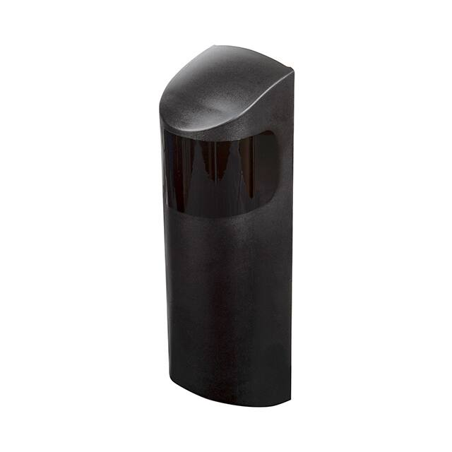
Type PD180CBT30Q/MU
• Designed for industrial doors and gates
• ESPE type 2, Performance level C
• Range 15 m or 30 m
• Modulated, infrared light
• Supply voltage: 12 to 24 VAC/DC (receiver)
• Supply voltage: 2 x ER14505 3.6 VDC size AA Lithium
batteries (emitter)
• SPST relay output
• SPST relay low battery
• LED for output indication
• Connection, terminal block
• Emitter test input
• CE (EN 12453, EN 12978) and UL325 approved
Product Description
The
PD180CBT30Q/MU
sensor is developed specifically for the domestic and
industrial door market. The
sensor meets the regulations
for industrial doors in Europe
and North America. The
robust polycarbonate housing allows flexible installation
as the lenses are adjustable
both in horizontal and vertical direction. The sensor is
easy to use and no sensitivity adjustments are necessary. The aspherical lens
design is superior to previous design of sensors with
built-in parabolic reflectors
that had corrosion and dust
Ordering Key
problems.
Increased safety by build-in:
- Sensor test function; the
emitter has a built-in test
input designed to mute the
emitter and thus evaluate the
sensor function. Test function is to be activated by the
door controller or the door
function can be activated by
a limit switch, magnet sensor
or a safety edge profile.
The receiver works with a
power-supply from 12 to
24 VAC/DC and the emitter is designed to use 2 x
ER14505 3.6 VDC size AA
Lithium batteries.
PD180CBT30Q/MU
Type
Housing style
Housing size
Housing material
Battery operated
Detection principle
Sensing distance
Output type
Output configuration
Mute function
Type Selection
Housing
Range
Ordering no.
size Sn Emitter
180 x 51 x 49 mm 30 m
PD180CBT30MU
Ordering no.
Receiver
PD180CBT30Q
Specifications Emitter
Rated operating dist (Sn) 15 m with jumper not
activated
30 m with jumper activated
Rated operational volt. (Ue) 2 x ER14505 3.6 VDC size AA
≥2700 mAh Lithium batteries
Battery lifetime
Jumper not active 15m => 2.5 years
Jumper active 30m => 1.5 years
Supply current
With Mute active (Io) Typ. 29 µA
Protection Reverse polarity, transients
Specifications are subject to change without notice (25.05.2018)
Mute input
Normal operation > 6 KΩ
Mute < 4 KΩ
Light source LED, 850 nm
Light spot size
@ 15 m setting 1.2 m @ 7.5 m
@ 30 m setting 2.4 m @ 15 m
Light type Infrared, modulated
Optical angle ± 4.1°
1
�PD180
Specifications Receiver
Rated operating dist. (Sn)
Blind zone
Temperature drift
Hysteresis (H)
Rated operational volt. (Ue)
AC: 45 Hz - 65 Hz
Ripple (Urrp)
Output
Contact ratings
Resistive loads
AC 1
DC 1
Mechanical life (typical)
Lifetime contacts (typical)
AC 1
DC 1
Minimum load power
No load supply current (Io)
+ Battery low alarm
15 or 30 m dependent on
emitter settings
None
≤ 0.4%/°C
3 - 20%
Supply class 2
12 to 24 VDC, -15% +10%
12 to 24 VAC, -15% +10%
≤ 10%
AgPd-Au
0.5 A/30 VAC
1 A/30 VDC
≥ 10 000 000 cycles
0.5 A/30 VAC 100 000
1 A/30 VDC 100 000
1 mW
≤ 36 mA DC (relay ON)
≤ 55 mA DC (both relays ON)
Ambient light
Incandescent light @
3000 … 3200 °K
Incandescent light 3200 °K
Fluorescent light
Stroboscopic light
Flashing beacon light
Optical angle
Protection
Operating frequency (f)
Response time OFF-ON (tON)
ON-OFF (tOFF)
Power ON delay (tv )
Indication function
Power ON
Output ON
≥ 100 000 lux (EN 60947-5-2)
≥ 10 000 lux* (EN 61496-2)
≥ 3 000 lux* (EN 61496-2)
0.05 J @ 200 Hz to 0.5 J @
5 Hz* (EN 61496-2)
3 to 5 J @ 0.5 to 2 Hz*
(EN 61496-2)
± 4.7°
Reverse polarity, transients
25 Hz
≤ 20 ms
≤ 20 ms
≤ 300 ms
LED, green
LED, yellow
* Failure to danger (worst case alignment)
General Specifications
Environment
Overvoltage category
Pollution degree
Degree of protection
Temperature
Operating
Storage
Vibration
Drop test
Lens adjustment
Adjustable optics
Rated insulation voltage
Housing material
Front
Backpart
Connection
Emitter
2
III (IEC 60664/EN 60947-1)
3 (IEC 60664/EN 60947-1)
IP 55 (IEC 60529; 60947-1)
-25° to +55°C (-13° to +131°F)
-25° to +80°C (-13° to +176°F)
10 to 150 Hz, 0.5 mm/7.5 g
(EN 60068-2-6)
2 x 1 m & 100 x 0.5 m
(IEC 60068-2-31)
Horisontal 200°
Vertical ±30°
50 VDC
PC black
PC black
Weight
Emitter
270 g
Receiver
230 g
UL-Approval
cURus UL325, CSA-C22.2 No.247
CE-marking
Yes
EN 12453, EN 12978,
EN 61496-1,
Type 2 ESPE
General reference Sensor designed according
to EN 60947-5-2
MTTFd related to combined
product life time (Rx+Tx) 110 years @ 40°C (+104°F)
(EN ISO 13849-1 (Parts
count method, annex D.1),
SN 29500)
ESPE architecture (Cat.) 2 (EN ISO 13849-1)
Performance level (PL.) C (EN ISO 13849-1)
PFHd 1.04 x 10⁻⁶ Errors per hour
(EN ISO 13849-1)
Mission Time 20 years (EN ISO 13849-1)
2 pole terminal block
Receiver 6 pole terminal bock
Specifications are subject to change without notice (25.05.2018)
�PD180
Operation Description
• The sensor shall be mounted with the draining hole facing down.
• The cable must be mounted pointing downwards to avoid water entering the sensor (See Dimensions).
• This product can only be used to detect direct interruption between Tx and Rx; it must not be reflected
• The sensors must be mounted on a hard vibration-free surface
• In order to obtain an “ESPE type 2” safety device, the sensors must be connected to a control system fittet with “Photo
test” or similar sensor verification function.
Operation Diagram
tv = Power ON delay
Emitter supply
low battery
Power supply (receiver)
Target emitter present
Object present
Mute active < 4 kΩ
Make (NO) Output ON
Output Battery
Dimensions
Detection Diagram
Sensing range [feet]
50.86
0,0
16,4
32,8
49,2
65,6
82,0
98,4
114,8
6,6
1,500
4,9
1,000
3,3
0,500
1,6
0,000
0,0
-0,500
-1,6
-1,000
-3,3
-1,500
-4,9
38.4
-2,000
0,00
5,00
10,00
15,00
20,00
25,00
30,00
Detection width [feet]
49.3
Detection width [m]
2,000
-6,6
35,00
Sensing range [m]
PD180 30m
PD180 15m
181
Excess Gain
1000
Excess Gain
100
15 m
30 m
10
1
1
10
100
Distance (m)
Specifications are subject to change without notice (25.05.2018)
3
�Wiring Diagram
Delivery Contents
Receiver
Emitter
1
2
2
1
12 to 24 VAC/DC
3
Mute input
4
Output
5
6
1A 30 VDC
0.5A 30 VAC
• PD180 emitter or receiver (separate box)
• Installation instruction in emitter box
• Packaging: Cardboard box
• 2 x 3 screws for raw plugs ø2.9 x 25 DIN 7981C
• 2 x 3 raw plugs for 8 mm hole
• 2 x 1 Strain releif
• 2 x 2 Screws for strain releif M3 x 12 mm
• 2 x 1 Cable gland
Battery
Installation Hints
To avoid interference from inductive voltage/
current peaks, separate the prox. switch
power cables from any other power cables,
e.g. motor, contactor or solenoid cables
Relief of cable strain
Protection of the sensing face
Switch mounted on mobile carrier
A proximity switch should not serve as
mechanical stop
Any repetitive flexing of the
cable should be avoided
Incorrect
Correct
The cable should not be pulled
4
Specifications are subject to change without notice (25.05.2018)
�