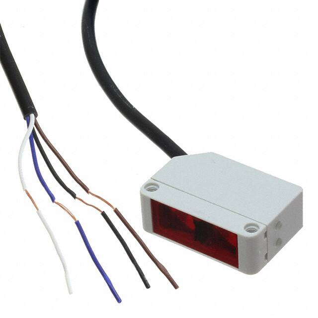
Photoelectrics
Retro-reflective
Type PD30CNR60....SA
• Miniature sensor range
• Range: 6 m
• Sensitivity adjustment by Potentiometer
• Modulated, infrared light 850 nm
• Supply voltage: 10 to 30 VDC
• Output: 100 mA, NPN or PNP preset
• Make and break switching function
• LED indication for output, stability and power ON
• Protection: reverse polarity, short circuit and transients
• Cable and plug versions
• Excellent EMC performance
Product Description
Ordering Key
The PD30CNR60 sensor
family comes in a compact
10 x 30 x 20 mm reinforced
PMMA/ABS housing.
The sensors are useful in
applications where high-accuracy detection as well as
small size is required.
Compact housing and high
power LED for excellent
performance-size ratio.
Type
Housing style
Housing size
Housing material
Housing length
Detection principle
Sensing distance
Output type
Output configuration
Connection type
Sensitivity adjustment
The Potentiometer function
for adjustment of the sensitivity makes the sensors
highly flexible. The output
type is preset (NPN or PNP),
and the output switching
function is NO and NC output.
PD30CNR60NAM5SA
Type Selection
Housing
Range
Connection
WxHxD
Sn
Ordering no.
NPN
Make and break switching
Ordering no.
PNP
Make and break switching
10 x 30 x 20 mm
10 x 30 x 20 mm
PD 30 CNR 60 NASA
PD 30 CNR 60 NAM5SA
PD 30 CNR 60 PASA
PD 30 CNR 60 PAM5SA
Specifications
6 m
6 m
Cable
Plug
EN 60947-5-2
Rated operating distance (Sn)
Ø 80 mm (ER4) reflector
≤6m
ER4060 reflector
≤4m
Blind zone
≤ 100 mm @ Ø80 mm (ER4)
and ER4060 reflector
Sensitivity
Electrical adjustment
210˚
Mechanical adjustment
240˚
Temperature drift
≤ 0.2%/ºC
Hysteresis (H)
5% to 20%
Rated operational volt. (UB )
10 to 30 VDC
(ripple included)
Ripple (Urpp )
≤ 10%
Output current
Continuous (Ie)
≤ 100 mA
Short-time (I)
≤ 100 mA
(max. load capacity 100 nF)
No load supply current (Io)
≤ 20 mA @ UB max
Minimum operational current (Im) ≤ 0.5 mA
Specifications are subject to change without notice (23.08.2017)
OFF-state current (Ir )
≤ 100 µA
Voltage drop (Ud )
≤ 2 VDC @ Ie max
Protection
Short-circuit, reverse polarity
and transients
Light source
LED, 850 nm
Light type
Infrared, modulated
Emitter angle
± 2º @ half sensing
distance
Light spot
110 mm @ 1.5 meters
Ambient light
≤ 10,000 lux
Operating frequency (f)
≤ 1000 Hz
Response time
OFF-ON (tON)
≤ 0.5 ms
ON-OFF (tOFF )
≤ 0.5 ms
Power ON delay (tv)
≤ 30 ms
Output function
Open collector
NPN or PNP by sensor type
Output switching function
N.O. and N.C.
1
�PD30CNR060...SA
Specifications (cont.)
Indication
Output ON
Power ON
Environment
Installation category
Pollution degree
Degree of protection
Ambient temperature
Operating
Storage
Vibration
Shock
LED, yellow
Signal stability ON and
LED, green. See curve for
condition of stability
III (IEC 60664/60664A;
60947-1)
3 (IEC 60664/60664A;
60947-1)
IP 67 (IEC 60529; 60947-1)
-25° to +60°C (-13° to +140°F)
-40° to +70°C (-40° to +158°F)
10 to 150 Hz, 1.0 mm/15 G
(IEC 60068-2-6)
30 g / 11ms, 3 pos, 3 neg
per axis
(IEC 60068-2-6, 60068-2-32)
Rated insulation voltage
≤ 500 VAC (rms)
Housing material
Body
ABS Light Grey
Frontglas
PMMA Red
Trimmer shaft
POM Dark Grey
Connection
Cable
PVC, black, 2 m
4 x 0.14 mm2, Ø = 3.3 mm
Plug
M8, 4-pin (CON. 54-series)
Weight
Cable version
≤ 50 g
Plug version
≤ 20 g
CE-marking Yes
Approvals
cULus (UL508 + CSA)
Operation Diagram
Tv = Power ON delay
Power supply
ON
OFF
Break Output (N.C.)
Present
Not Present
Tv
ON
OFF
Make Output (N.O.)
ON
OFF
Target
Tv
Signal Stability Indication
Wiring Diagrams
NPN
2WH
4BK
Excess Gain
1.10
Operation level x 1.10
1.0
0.90
Operation level
Operation level x 0.90
3BU
PNP
Time
Green LED ON
Yellow LED ON
1BN
1BN
4BK
2WH
3BU
2
Specifications are subject to change without notice (23.08.2017)
�PD30CNR60....SA
Detection Diagram
Excess Gain
Sensor
Y
ER4
Reflector
3,2
6,6
9,8
(mm)
300
13,1 16,4 19,7 23,0 26,2
11,8
200
7,9
100
3,9
0
0,0
-100
-3,9
-200
-7,9
-300
-11,8
0
1
2
3
4
5
Distance (m)
6
7
8
Distance (Feet)
3,2
0,3
10
32,8
10
Excess Gain
0,0
Distance (Feet)
(Inches)
X
1
0,1
1,0
Distance (m)
10,0
1
Dimensions
Plug version
10.6
20
20
10.6
Cable version
Optical axis
10.8
17
Receiver
R
Optical axis
Incorrect
xxxxxxS
Two M3
Potentiometer
Two, 9.5 dia.
Lenses
15
30
Correct
15
22
30
25.4
xxxxxxS
Two, 9.5 dia.
Lenses
10.6
10-30 V
100 mA
BN: V+
UL
BU: VBK: OUT
WH: ET
7
Receiver
PD30CNP
06NPM5T
25.4
17
R
Potentiometer
Power / Stability LED
Green
5.5 5.5
10.8
1.1
10.6
7
10-30 V
100 mA
BN: V+
UL
BU: VBK: OUT
WH: ET
5.5 5.5
1.1
PD30CNP
06NPM5T
Output LED
Yellow
Power / Stability LED
Green
22
Output LED
Yellow
Emitter
Two M3
> 100 mm
Emitter
10.25
Installation Hints
To avoid interference from inductive voltage / Relief of the cable strain
current peaks, separate the proximity switch
cables from any other power cables. E.g.
Engine, contactor or solenoid cables
Protection of the sensing face
Sensor mounted on a mobile carrier
Incorrect
Incorrect
Incorrect
Correct
Correct
> 100 mm
The cable should not be pulled
A proximity switch should not serve
as mechanical stop
Any repetitive flexing of the
cable should be avoided
Accessories
Delivery Contents
• Mounting bracket APD30-MB1 or APD30-MB2 to be
purchased separately.
• Photoelectric switch: PD30CNR60 ...
• Screwdriver
• Packaging: Plastic bag
Specifications are subject to change without notice (23.08.2017)
3
�
很抱歉,暂时无法提供与“PD30CNR60PASA”相匹配的价格&库存,您可以联系我们找货
免费人工找货- 国内价格 香港价格
- 5+708.546645+88.27243
