D10 Expert Series - Small Object Counter
Datasheet
Advanced sensor for small object counting
•
•
•
•
•
•
•
•
•
•
Easy-to-set selectable threshold with automatic compensation
algorithm
Automatic compensation algorithm compensates for dust or
contamination on the fiber optic array and for ambient temperature
changes
16-bit microcontroller and 12-bit Analog-to-Digital converter (ADC) for
high-performance, low-contrast sensing
Easy-to-read 4-digit display for Health Mode, Percentage Blocked,
Signal Level, or Counter Mode readout, plus indicators for a continuous
readout of operating status (user configurable)
Sleek, ultra-slim 10 mm housing, mounts to a standard 35 mm DIN rail
Single discrete output plus Health Mode output to indicate preventative
maintenance is required
Three-mode power and speed selection to optimize detection reliability
Dynamic event stretcher to ensure one output per event — especially
for gel-cap style pills
Visible red (680 nm) sensing beam
Models available with 2 m or 9 m (6.5 ft or 30 ft) cable or integral Picostyle quick-disconnect
Sensors
Models
Cables
Discrete Outputs
NPN
D10DNCFP
2 m (6.5 ft) Cable
D10DNCFPQ
6-pin Pico-style QD
D10DPCFP
2 m (6.5 ft) Cable
D10DPCFPQ
6-pin Pico-style QD
PNP
Fiber Optic Arrays
Models 1
PFCVA-10X25-S
PFCVA-10X25-E
PFCVA-25X25-S
PFCVA-25X25-E
PFCVA-34X25-S
PFCVA-34X25-E
Detection Window
Dimensions
Fiber Exit
Side exit
10 mm x 25 mm
End exit
Side exit
25 mm x 25 mm
End exit
Side exit
34 mm x 25 mm
End exit
Minimum Object Size 2
1.5 mm
3 mm
4 mm
To order the 9 m (30 ft) cable model, add suffix "W/30" to the cabled model number. For example: D10DNCFP W/30.
Models with a QD connector require a mating cable.
1 Custom fiber arrays and mounting configurations are possible. Consult factory for assistance with your small object counting
application.
2 With 2% threshold offset percentage
Original Document
146132 Rev. D
29 August 2014
146132
�D10 Expert Series - Small Object Counter
WARNING: Not To Be Used for Personnel Protection
Never use this device as a sensing device for personnel protection. Doing so could lead to
serious injury or death. This device does not include the self-checking redundant circuitry necessary
to allow its use in personnel safety applications. A sensor failure or malfunction can cause either an
energized or de-energized sensor output condition.
Overview
The D10 Expert Small Object Counter sensor is a high-performance plastic
fiber optic amplifier that has been optimized for small object counting
using through-beam fiber optic arrays. Fiber optic arrays emit and receive
light over an area instead of a narrow beam. Having an area of light
makes alignment and positioning control of the object less critical than
using single point emitter and receiver fiber optic assemblies. Because the
object only breaks part of the fiber optic array, reliable detection requires
very precise thresholds, an auto compensation tracking algorithm, and
high speed electronics to make split-second decisions.
The setup and configuration of the advanced D10D sensor has been
reduced to the act of applying power to the device with the fiber optic
assemblies rigidly mounted in position. The user also has access to a
comprehensive collection of setup and configuration parameters through
the sensor’s advanced setup menu, but for most applications the default
options provide superb performance and reliability.
1
3
2
Upon power-up, the clear-state light level is measured and appropriate
switching thresholds are established, making the fiber optic sensor
system a stable, fast, and reliable small object counter. The clear-state
light level can be reset by performing a 2 second hold on the dynamic (+)
push button or single-clicking the remote line.
4
Continued reliable operation is ensured as the thresholds adapt to
changing signal levels over time using Banner Engineering’s auto
compensation tracking algorithm. The sensor continuously tracks the
clear-state light level and makes fine adjustments to the switching
thresholds as required because of dust or contamination building up on
the fiber optic array and for ambient temperature changes.
5
dynamic
The sensor features either two NPN or two PNP outputs, depending on
your model. Each output serves a different purpose. The discrete output 1
(white wire) switches whenever an object breaks the fiber optic array and
can be used for counting. The Health Mode output 2 (black wire) switches
when the fiber optic array becomes contaminated to a point that the auto
compensation tracking algorithm cannot sufficiently adjust the thresholds
to ensure reliable detection (see Health Mode Alarm on page 3).
6
The duration of the discrete output 1 (white wire) can be increased
(stretched) to ensure accurate counting. The amount of increase is a user
configurable percentage of the detection event duration; the default
increase time is 50% more than the event duration. Banner calls this
feature a Dynamic Event Stretcher (DES), and it prevents errant double
counts of translucent gel-caps and other small objects of that type. The
DES provides a “smart” OFF-delay that is independent of application
speed and can be adjusted from 0% to 100% of the detection event
duration.
static
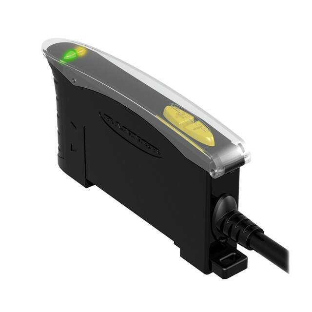
Figure 1. D10D Features
1. Counting output indicator
2. Arrow icons
3. Health mode output indicator
4. 4-digit display
5. Light/dark operate, clock, and lock
icons
6. Programming push buttons
2
www.bannerengineering.com - Tel: +1-763-544-3164
P/N 146132 Rev. D
�D10 Expert Series - Small Object Counter
Health Mode Alarm
The Health Mode Alarm alerts you when preventative maintenance becomes necessary to ensure reliable sensing. The
Health Mode output 2 is Active when the system is OK and operating normally. Health Mode output 2 becomes Inactive
when the system is in a marginal state because of contamination. The system still operates normally and can detect small
objects, but is nearing the alarm state. When the system is completely contaminated and unable to ensure reliable
sensing, the system goes into the alarm state. In the alarm state, the discrete output 1 is forced to the blocked state and
can no longer be used to detect small objects.
The sensor may enter Health Mode Alarm for any of these reasons:
1. When first powered up; the fiber optic array may already be contaminated
2. If the Window SET procedure fails, indicating the fiber optic array is contaminated and the sensor could not set a
valid clear-state light level for reliable detection
3. If the fiber optic array is contaminated enough that the auto compensation tracking algorithm cannot sufficiently
adjust the thresholds to ensure reliable detection
4. If the fiber optic array is blocked for more than 2 seconds
Return the system to normal operation by cleaning the fiber optic array and performing a Window SET to reset the clearstate light level (see Single-Point Window SET on page 7).
Health Model Display
Display Value
3
Outputs and Indicators
System Status
Discrete output 1: Operational
25 to 100
Health Mode output 2: Active
OK: system operating normally
Indicators: Arrow Icons 1 & 2 GREEN
Discrete output 1: Operational
1 to 20
Health Mode output 2: Inactive
Marginal: System operating normally;
preventative maintenance
recommended
Indicators: Arrow Icon 1 Green; Arrow Icon 2 Red
Discrete output 1: Forced to Blocked State (i.e. in dark
operate, the output is conducting)
0
Health Mode output 2: Inactive
Alarm: System not operational; system
maintenance required
Indicators: Arrow Icons 1 & 2 Red
Programming Options
Light/Dark Operate Selection. Toggle to select the condition for which the output will conduct: when the object is
present or when the object is absent.
Threshold Offset Percentage. 2%, 3%, 4%, 5%, 10%
Dynamic Event Stretcher (DES) Selection. The output is held ON (OFF in Light Operate) for a percentage of time
longer than the detection event duration.
Options: 0%, 25%, 33%, 50%, 100%
(e.g., If the Dynamic Event Stretcher was set at 50%, a 1 ms event would be stretched to 1.5 ms)
Display Orientation. Normal or inverted
Display Mode. Health Mode (100%–0%); Percentage Blocked (0%–100%); Signal Level (ADC value); or Counter Mode
(0–9999)
Power Level/Speed Selection. High-Speed (HS) (150 µs response, 50 µs repeatability); High-Power (HP) (225 µs
response, 75 µs repeatability); or Super High-Power (SHP) (300 µs response, 100 µs repeatability)
3 Sensor display must be in Health Mode (see Sensor Setup on page 4)
P/N 146132 Rev. D
www.bannerengineering.com - Tel: +1-763-544-3164
3
�D10 Expert Series - Small Object Counter
Factory Default Settings. The following settings are preset at the factory; revert sensor to factory defaults using
Advanced Setup procedure (see Advanced Setup on page 6)
• Dark Operate (DO)
• 50% DES
• Health Mode Display
• 2% Threshold Offset Percentage
• Normal Display Orientation
• High Speed (HS)
Sensor Programming
Programming Procedures. Use the Dynamic (+) and Static (-) buttons to access and set programming parameters. For
remote programming, connect a switch or digital input to the gray wire (remote line); the length of the individual pulses is
equal to the value T when 0.04 seconds ≤ T ≤ 0.8 seconds.
Returning to RUN mode. Exit Setup mode by stepping through the entire Setup process (see Sensor Setup on page
4), by escaping out of the Setup process, or by exceeding the 60 second inactivity time-out. To escape out of the Setup
process, press and hold both the Static (-) and Dynamic (+) buttons for 2 seconds. (For remote programming, press and
hold the remote line for 2 seconds). The sensor always saves the selected settings and returns to Run mode.
Sensor Setup
•
•
•
•
Configures sensor display and operating parameters.
Changes are updated instantly.
Click Dynamic (+) or double-pulse remote line to select an option.
Click Static (-) or single-pulse remote line to advance.
Remote input pulse: 0.04 s ≤ T ≤ 0.8 s
1. Access Setup mode.
Method
Action
Push Button
Press and hold both the Dynamic (+) and
Static (-) buttons concurrently for more than 2
seconds
Remote Input
Double-pulse the remote line
Result
•
•
•
Arrow Icon 1 ON Red
Arrow Icon 2 OFF
Display shows “Threshold Offset
Percentage” option.
2. Select the threshold offset percentage.
Method
Action
Result
Click Dynamic (+) to toggle between selections
Push Button
Remote Input
Click Static (-) to save selection and advance
to “Light/Dark Operate”
2% to 10% Threshold Offset Percentage:
“t 2,” “t 3,” “t 4,” “t 5,” “t 10”
Double-pulse remote line to toggle between
selections
Single-pulse the remote line to save selection
and advance to “Light/Dark Operate"
3. Select light operate or dark operate.
4
www.bannerengineering.com - Tel: +1-763-544-3164
P/N 146132 Rev. D
�D10 Expert Series - Small Object Counter
Method
Push Button
Action
Result
Click Dynamic (+) to toggle between selections
Light Operate:
• Display flashes “lo”
• L icon ON
Click Static (-) to save selection and advance
to “Dynamic Event Stretcher (DES)”
Double-pulse remote line to toggle between
selections
Remote Input
Dark Operate:
•
•
Single-pulse the remote line to save selection
and advance to “Dynamic Event Stretcher
(DES)”
Display flashes “do”
D icon ON
4. Select dynamic event stretcher (DES).
Method
Push Button
Remote Input
Action
Result
Click Dynamic (+) to toggle between selections
OFF (No DES):
• “d 0”
• Clock icon OFF
Click Static (-) to save selection and advance
to “Display Mode”
Double-pulse remote line to toggle between
selections
Single-pulse the remote line to save selection
and advance to “Display Mode”
25%, 33%, 50%, or 100% DES:
• “d 25,” “d 33,” “d 50,” “d 100,”
• Clock icon ON
5. Select display mode.
Method
Action
Result
Click Dynamic (+) to toggle between selections
Push Button
Click Static (-) to save selection and advance
to "Power/Speed"
Health Mode:
“HLth”
Percentage Blocked: “Pctb”
Remote Input
Double-pulse remote line to toggle between
selections
Single-pulse the remote line to save selection
and advance to “Power/Speed"
Signal Level:
“1234”
Counter Mode:
“Cntr”
6. Select the speed and power combination.
P/N 146132 Rev. D
www.bannerengineering.com - Tel: +1-763-544-3164
5
�D10 Expert Series - Small Object Counter
Method
Push Button
Action
Result
Click Dynamic (+) to toggle between selections
Arrow Icons 1 and 2 ON Red
To return to Run mode, click the Static (-)
button OR To proceed to Advanced Setup,
quad-click Static (-) button
High-speed (150-µs response): “HS”
High-power (225-µs response): “HP”
Double-pulse the remote line to toggle between
selections
Remote Input
Single-pulse the remote line to save selection
and return to RUN mode OR Quad-click the
remote line to proceed to Advanced Setup
Super-high-power (300-µs response):
“SHP”
See Advanced Setup on page 6.
Advanced Setup
•
•
•
•
•
Advanced adjustments to previously configured sensor display and operating parameters.
Quad-click Static (-) or quad-pulse remote line before exiting “Speed and Power Combination” selection to enter
this mode
Click Dynamic (+) or double-pulse remote line to select an option.
Click Static (-) or single-pulse remote line to advance.
Changes are updated instantly.
Remote input pulse: 0.04 s ≤ T ≤ 0.8 s
1. Enter Advanced Setup mode.
Method
Action
Push Button
From “Power and Speed” mode, quad-click
Static (-) button
Remote Input
From “Power and Speed” mode, quad-pulse the
remote line
Result
•
•
Arrow Icons 1 and 2 ON Red
Display shows “Factory Default
Settings” option.
2. Set to the factory default settings.
Method
Push Button
Remote Input
Action
Result
Click Dynamic (+) to toggle between selections
Returns to factory default settings
Click Static (-) to advance to “Display
Orientation”
Factory Default Settings Not Selected:
Double-pulse the remote line to toggle between Display shows “Fd n”
selections
Factory Default Settings Selected: Display
Single-pulse the remote line to advance to
“Display Orientation”
shows “Fd y”
3. Set the display orientation.
Method
Push Button
Remote Input
6
Action
Result
Click Dynamic (+) to toggle between selections
Inverts display to read “upside-down”
Click Static (-) to return to RUN mode
Double-pulse the remote line to toggle between
selections
Single-pulse the remote line to return to RUN
mode
Normal:
Inverted:
The icons do not invert.
www.bannerengineering.com - Tel: +1-763-544-3164
P/N 146132 Rev. D
�D10 Expert Series - Small Object Counter
Push Button Lockout
•
•
Prevents unwanted adjustments or tampering of the push buttons.
Push buttons can be enabled or disabled only from the remote line and only during normal RUN mode.
Remote input pulse: 0.04 s ≤ T ≤ 0.8 s
Method
Action
Result
Push Button
Not available with push-button
programming
Remote Input
From RUN mode, quad-pulse the remote
line to toggle between selections
Push Buttons Disabled
• Display flashes “loc”
• Padlock icon appears
• Sensor remains in RUN mode
Push Buttons Enabled
• Display flashes “uloc”
• Padlock icon disappears
• Sensor remains in RUN mode
Gate Input
The pink wire is configured as a gate input. When this wire is pulled low (e.g., to the sensor ground), it inhibits the outputs
from switching while all other sensor functions continue to be enabled. This feature is useful for controlling when the
outputs are allowed to change states. Gate input function response time is 1 millisecond.
Single-Point Window SET
A Window SET sets a single output condition that extends above
and below the taught condition by a selectable offset percentage (2,
3, 4, 5, or 10%).
Taught
Condition
In Dark Operate, a Window SET sets a single OFF condition that
extends above and below the taught condition. All other conditions
(lighter or darker) result in ON output.
In Light Operate, a Window SET sets a single ON condition that
extends above and below the taught condition. All other conditions
(lighter or darker) result in OFF output.
Output ON and OFF conditions can be reversed by changing Light/
Dark Operate status in SETUP mode.
Remote input pulse: 0.04 s ≤ T ≤ 0.8 s
P/N 146132 Rev. D
Offset %
Offset %
Output ON
Darkest
(no signal)
Output OFF
Sensor positions
window thresholds
from the taught
condition
Output ON
Most Light
(saturated
signal)
Figure 2. Single-point Window Set and Offset Percentage
(Dark Operate Shown)
www.bannerengineering.com - Tel: +1-763-544-3164
7
�D10 Expert Series - Small Object Counter
Set Clear-State Light Level of Single-Point Window
Method
Push Button
Remote Input
Action
Result
1. Verify the fiber optic array is clean
and clear of any objects.
Display turns OFF and Arrow Icons 1 and 2 toggle 3 times
green while the sensor is optimizing system settings.
2. Press and hold Dynamic (+) button
for more than 2 seconds.
TEACH
•
•
•
•
conditions acceptable:
Display flashes “PASS”
Sensor returns to Run mode with new settings.
Arrow Icons 1 and 2 turn ON Green
Health Mode output 2 Active
TEACH
•
•
•
conditions unacceptable:
Display flashes “FAIL”
Arrow Icons 1 and 2 turn ON Red
Health Mode output 2 Inactive
1. Make sure fiber optic array is clean
and clear of any objects.
2. Single-pulse the remote line.
Wiring Diagrams
Wiring for quick disconnect (QD) models are functionally identical.
NPN Output Models
bu
bn
wh
bk
load
−
12–24V dc
+
1
2
health
gy
pk
PNP Output Models
Teach
Gate
bn
bu
wh
bk
gy
pk
load
health
+
12–24V dc
−
1
2
Teach
Gate
D10D...Port Locations
Slides Up to
Release Fibers
Plastic Fiber Emitter Port
Plastic Fiber Receiver Port
8
www.bannerengineering.com - Tel: +1-763-544-3164
P/N 146132 Rev. D
�D10 Expert Series - Small Object Counter
Specifications
Required Fiber Optics
PFCVA models (Custom fiber arrays and mounting configurations are
possible. Consult factory for assistance with your small object counting
application.)
Sensing Beam
Visible red, 680 nm
Supply Voltage and Current
12 to 24 V dc (10% maximum ripple) at less than 65 mA, exclusive of
load
Supply Protection Circuitry
Protected against reverse polarity and transient voltage
Output Protection Circuitry
Protected against false pulse on power-up and continuous short-circuit
Output Configuration
2 NPN or 2 PNP, depending on model
Output Rating
150 mA maximum load
OFF-state leakage current: < 10 µA at 24 V dc
ON-state saturation voltage: NPN < 1.5 V at 150 mA load; PNP < 2.5 V
at 150 mA load
Output Response Time
Programmable, 150 µs, 225 µs, 300 µs
NOTE: < 1 second delay on power-up; outputs do not conduct during
this time.
Adjustments
Push-button or remote programming of threshold offset percentage,
light/dark operate, Dynamic Event Stretcher (DES), display, and
power/speed
Installation
35 mm DIN rail or included mounting bracket
Indicators
Four-digit digital display, 2 arrow icons, push-button lockout, Dynamic
Event Stretcher, light/dark operate selection, and 2 amber output LEDs
Certifications
Construction
Black ABS/polycarbonate alloy (UL94 V-0 rated) housing, clear
polycarbonate cover
Environmental Rating
NEMA 1, IEC IP50
Operating Conditions
Temperature: –20 to 55 °C (–4 to 131 °F)
Storage Temperature: –20 to 80 °C (–4 to +75 °F)
Max. Rel. Humidity: 90% at 50 °C (non-condensing)
Number of
Devices, Stacked
Ambient Temp
Rating
Load
Specification
3
55 °C
150 mA
7
50 °C
50 mA
10
45 °C
50 mA
Connections
PVC-jacketed 2 m or 9 m (6.5 ft or 30 ft) 6-wire integral cable or
integral 6-pin Pico-style quick-disconnect
D10D...Sensor Dimensions
10.5 ± 0.2 mm (typ.)
(0.41")
35.9 mm
(1.41")
7.6 mm
0.30"
9.8 mm
(0.39")
Mounting Bracket
(included)
61.3 mm
(2.42")
68.1 mm
(2.68")
P/N 146132 Rev. D
www.bannerengineering.com - Tel: +1-763-544-3164
9
�D10 Expert Series - Small Object Counter
Included Bracket Dimensions
5.0 mm
(0.20")
35.1 mm
(1.38")
15.2 mm
(0.60")
M3 Hardware included:
Lock Washer (2)
Flat Washer (2)
Screws (2)
Hex Nuts (2)
8.6 mm
(0.34")
10.0 mm
(0.39")
5.0 mm (0.20")
2x 3.5 mm
(0.14")
2.5 mm (0.10")
25.4 mm
(1.00")
16.0 mm
(0.63")
2 x ø3.3 mm (0.13")
2x ø3.2 mm (0.13")
10.0 mm
(0.39")
2x C’sink
ø8.0 mm (0.31")
3.2 mm (0.13") deep
ø4.4 mm (0.18") thru
Fiber Optic Array Dimensions
14.5 mm
[0.57”]
83 mm
[3.27”]
42 mm
[1.65”]
30 mm
[1.18”]
10 mm
[0.39”]
25 mm
[0.98”]
4x 3.2 mm dia [0.13”]
75 mm
[2.95”]
Figure 3. PFCVA-10X25-S and PFCVA-10X25-E
10
www.bannerengineering.com - Tel: +1-763-544-3164
P/N 146132 Rev. D
�D10 Expert Series - Small Object Counter
14.5 mm
[0.57”]
83 mm
[3.27”]
42 mm
[1.65”]
30 mm
[1.18”]
25 mm
[0.98”]
4x 3.2 mm dia [0.1260”]
25 mm
[0.98”]
75 mm
[2.95”]
Figure 4. PFCVA-25X25-S and PFCVA-25X25-E
14.5 mm
[0.57”]
83 mm
[3.27”]
25 mm
[0.98”]
34 mm
[1.34”]
30 mm
[1.18”]
42 mm
[1.65”]
4x 3.2mm dia [0.1260”]
75 mm
[2.95”]
Figure 5. PFCVA-34X25-S and PFCVA-34X25-E
P/N 146132 Rev. D
www.bannerengineering.com - Tel: +1-763-544-3164
11
�D10 Expert Series - Small Object Counter
Accessories
6-Pin Snap-on M8/Pico-Style Cordsets
Model
Length
PKG6Z-2
2 m (6.5 ft)
PKG6Z-9
9 m (30 ft)
Style
Dimensions
Pinout
ø10 mm max.
(0.4")
Straight
3
28 mm max.
(1.1")
PKW6Z-2
2 m (6.5 ft)
PKW6Z-9
9 m (30 ft)
6
2
25 mm max.
(1.0")
20 mm
(0.8")
Right-angle
4
5
1
1
2
3
4
5
6
- brown
= White
= Blue
= Black
= Gray
= Pink
ø12 mm max.
(0.5")
Banner Engineering Corp. Limited Warranty
Banner Engineering Corp. warrants its products to be free from defects in material and workmanship for one year following the date of shipment. Banner Engineering Corp.
will repair or replace, free of charge, any product of its manufacture which, at the time it is returned to the factory, is found to have been defective during the warranty
period. This warranty does not cover damage or liability for misuse, abuse, or the improper application or installation of the Banner product.
THIS LIMITED WARRANTY IS EXCLUSIVE AND IN LIEU OF ALL OTHER WARRANTIES WHETHER EXPRESS OR IMPLIED (INCLUDING, WITHOUT LIMITATION,
ANY WARRANTY OF MERCHANTABILITY OR FITNESS FOR A PARTICULAR PURPOSE), AND WHETHER ARISING UNDER COURSE OF PERFORMANCE, COURSE
OF DEALING OR TRADE USAGE.
This Warranty is exclusive and limited to repair or, at the discretion of Banner Engineering Corp., replacement. IN NO EVENT SHALL BANNER ENGINEERING CORP. BE
LIABLE TO BUYER OR ANY OTHER PERSON OR ENTITY FOR ANY EXTRA COSTS, EXPENSES, LOSSES, LOSS OF PROFITS, OR ANY INCIDENTAL,
CONSEQUENTIAL OR SPECIAL DAMAGES RESULTING FROM ANY PRODUCT DEFECT OR FROM THE USE OR INABILITY TO USE THE PRODUCT, WHETHER
ARISING IN CONTRACT OR WARRANTY, STATUTE, TORT, STRICT LIABILITY, NEGLIGENCE, OR OTHERWISE.
Banner Engineering Corp. reserves the right to change, modify or improve the design of the product without assuming any obligations or liabilities relating to any product
previously manufactured by Banner Engineering Corp.
www.bannerengineering.com - Tel: +1-763-544-3164
�