Photoelectrics
Through-beam for Separate Amplifier
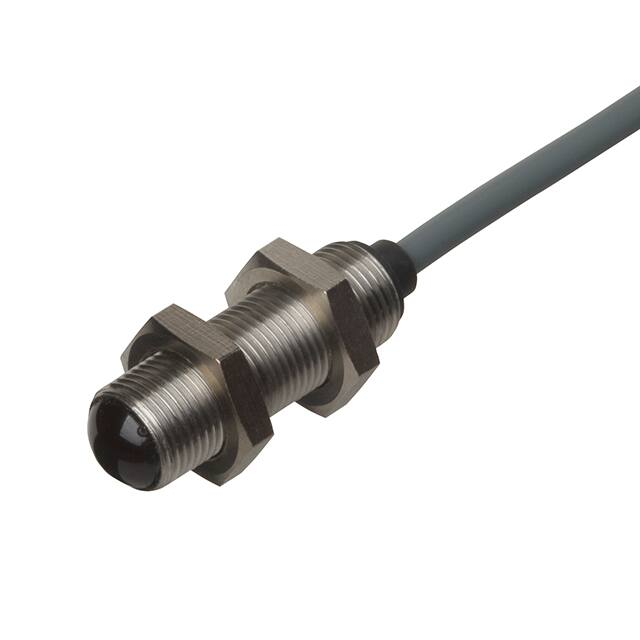
Types MOFT, MOFR
• Built-in lens: 2°, 5° or 8°
• Range: 20 m or 50 m
• Modulated infrared light
• High immunity to ambient light
• For amplifier series S142. and S143.
• Degree of protection IP 66/IP 67
• For harsh environment
• High penetration power
• 15 m shielded PVC cable
• Ø 10 mm polycarbonate housing or M12 or
M14 stainless steel
Product Description
Ordering Key
Small through beam pho
to
elec
tric switch. Range up
to 50 m. 3 beam angles.
Waterproof, for dirty environ
ment, i.e. water, dust, steam
etc. To be used with ampli
Type
Emitter
Range
Housing diameter
Optical angle
fiers series S142. - S143.
15 m shield
ed cable, PVC.
Ø 10 x 42 mm polycarbonate
or M12 or M14 stainless steel
housing. Straight optical axis.
MOF T 20-M12-2
Type Selection
Housing
diameter
Rated
Optical
Ordering no.:
operating angle Emitter
dist. (Sn)
Ordering no.:
Receiver
Ø 10 mm
2°
MOFR
5°
MOFR-5
8°
MOFR-8
20 m
2°
MOFT 20
20 m
5°
MOFT 20-5
20 m
8°
MOFT 20-8
50 m
2°
MOFT 50
M12
20 m
20 m
20 m
50 m
2°
5°
8°
2°
5°
8°
2°
MOFR-M12-2
MOFR-M12-5
MOFR-M12-8
MOFT 20-M12-2
MOFT 20-M12-5
MOFT 20-M12-8
MOFT 50-M12-2
M14
8°
20 m
8°
MOFT 20-M14-8
MOFR-M14-8
Specifications Emitter
Rated operational volt. (Ue)
Supply current (IO)
3 V, (square wave)
supplied by amplifier
MOFT 20
≤ 15 mA
MOFT 20-5 ≤ 50 mA
MOFT 20-8 ≤ 50 mA
MOFT 50
≤ 50 mA
Specifications are subject to change without notice (14.08.2017)
Light source GaAIAs LED, 880 nm
Light type Infrared, modulated
Optical angle ± 2°, ± 5°, ± 8°
Indications
On amplifier
Protection
Short-circuit, reverse polarity
1
�MOFT, MOFR
Specifications Receiver
Rated operational volt. (Ue) 8 VDC supplied by amplifier
Rsource 470Ω
Supply current (IO)
≤ 11 mA
Sensitivity
Adjustable on amplifier
Optical angle ± 2°,± 5°, ± 8°
Ambient light 10,000 lux (sensitivity ±5%)
Note: The actual range will be
within ±5% of the set range at
an ambient light of 10,000 lux
Operating frequency (f) See amplifier data
Response time (tOFF & tON) See amplifier data
Power ON delay (tv)
See amplifier data
Indications
On amplifier
Protection
Short-circuit, reverse polarity
General Specifications
Dimensions
Environment
Overvoltage category III (IEC 60664/60664A; 60947-1)
Pollution degree 3 (IEC 60664/60664A; 60947-1)
Degree of protection IP 66/IP 67 (IEC 60529; 60947-1)
Temperature
Operating
-20° to +60°C (-4° to +140°F)
Storage
-40° to +80°C (-40° to +176°F)
Vibration
10 to 150 Hz, 0.5 mm/7.5 g
(IEC 60068-2-6)
Shock
2 x 1 m & 100 x 0.5 m
(IEC 60068-2-6)
Dielectric voltage 500 VAC (rms)
Housing material Polycarbonate, black
Connection cable
Emitter Grey, 15 m oilproof PVC,
Ø 4 mm, 1 x 0.25 mm2,
shielded
Receiver Black, 15 m oilproof PVC,
Ø 4 mm, 1 x 0.25 mm2,
shielded
Weight (cable incl.)
347 g emitter
347 g receiver
CE-marking
Yes
2° and 5° types
8° types
Wiring Diagrams
Rx 1
Receiver
(black cable)
Emitter
(grey cable)
Tx 2
Rx 3
1
Rx
Tx 31
Power
supply
2
8
9
2
(+)
7
3
Alarm output NPN
S142....
6
5
4
Output NPN
Tx 1
Rx 2
(-)
S143....
1
11
10
Power Supply
Specifications are subject to change without notice (14.08.2017)
�MOFT, MOFR
Installation
Mounting
1) When installing the sensors, make sure that the maxi
mum range is not exceeded and - if two separate sys
tems are mounted close to each other - place the sen
sors so cross-talk is avoided.
2) To protect the receiver and the transmitter from dam
age, proper fittings must be used in the installation.
3) Connect the receiver and the emitter to the dedicated
terminals on the S142... system.
Installation Hints
To avoid interference from inductive voltage/
current peaks, separate the prox. switch
power cables from any other power cables,
e.g. motor, contactor or solenoid cables
Relief of cable strain
Protection of the sensing face
Switch mounted on mobile carrier
A proximity switch should not serve as
mechanical stop
Any repetitive flexing of the
cable should be avoided
Incorrect
Correct
The cable should not be pulled
Delivery Contents
Accessories
• MOFT.. and MOFR
• All M12-types: 2 pcs. M12 nuts
• All M14-types: 2 pcs. M14 nuts
• Packaging: Plastic bag, emitter and receiver packed
separately
• Mounting bracket MB-M01
Specifications are subject to change without notice (14.08.2017)
3
�
很抱歉,暂时无法提供与“MOFT20-M12-8”相匹配的价格&库存,您可以联系我们找货
免费人工找货