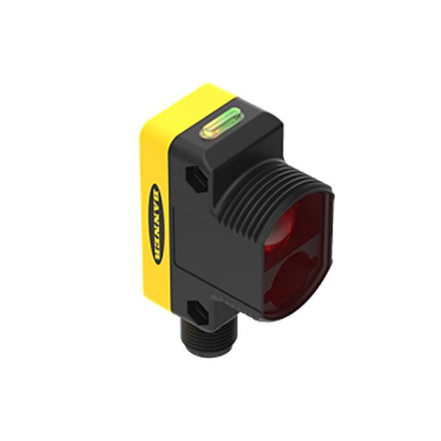
WORLD-BEAM® QS30AF Sensor
Datasheet
Push-Button-SET Adjustable-Field Sensor
•
•
•
•
•
•
•
•
•
•
Push-button adjustable-field background suppression sensor detects objects within a
defined sensing field, while ignoring objects located beyond the sensing field cutoff
Easy cutoff point push-button SET options: Background Suppression SET, Object
Detection SET and Dynamic SET, plus manual adjustments
Easy push-button N.O./N.C. and output OFF-delay setup
Powerful, highly collimated visible red sensing beam
Tough ABS housing is rated IEC IP67; NEMA 6
Easy-to-read operating status indicators, with 8-segment bar graph display
Bipolar discrete outputs, PNP and NPN
Selectable 30 millisecond OFF-delay
Models available with 2 m or 9 m (6.5 ft or 30 ft) cable or integral quick-disconnect
Compact housing, mounting versatility – via popular 30 mm threaded barrel or side-mount
WARNING:
• Do not use this device for personnel protection
• Using this device for personnel protection could result in serious injury or death.
• This device does not include the self-checking redundant circuitry necessary to allow its use in personnel safety
applications. A device failure or malfunction can cause either an energized (on) or de-energized (off) output condition.
Models
Model
Cutoff
QS30AF
QS30AFQ
Cable1
Supply Voltage
Output Type
10 V DC to 30 V DC
Bipolar NPN/PNP
Sensing Mode
Sensing Beam
2 m (6.5 ft) 5-wire cable
50 mm to 300 mm (2 in
to 12 in)
Integral 5-pin Eurostyle quick disconnect
Visible red, 660 nm
DIFFUSE
Overview
Yellow Output Conducting
Indicator
Green Power ON
Indicator
The QS30AF is an easy-to-use triangulation sensor which provides a
sophisticated, yet cost-effective solution for demanding applications.
The sensor features two identically configured outputs, one NPN and
one PNP. The sensor’s compact housing has a large, easy-to-see bar
graph display plus bright LEDs for easy configuration and status
monitoring during operation. The sensor can be side-mounted, using its
integral mounting holes, or front-mounted, via its 30 mm threaded barrel.
Configuration
Push
Buttons
Bargraph
Display
Cutoff
Switchpoint
SETUP Status
Indicators:
Delay
Normally Closed
Normally Open
Figure 1. QS30 Features
1 Integral 2 m (6.5 ft) unterminated cable models are listed.
• To order the 9 m (30 ft) PVC cable model, add the suffix "W/30" to the cabled model number.For example, QS30AF W/30.
• Models with a quick disconnect require a mating cordset.
Original Document
111384 Rev. D
22 June 2020
111384
�WORLD-BEAM® QS30AF Sensor
Optical Triangulation
PSD Receiver
Element
R
Signal
Conditioning
Circuitry
Near
Limit
Lenses
Far
Limit
Target Movement
Microprocessor
Output
Circuitry
Emitter
Circuitry
E
Laser
Emitter
The function of the QS30AF is based on optical triangulation.
The emitter circuitry and optics create a light source which is
directed toward a target. The light source bounces off the
target, scattering some of its light through another lens to
the sensor's position-sensitive device (PSD) receiver
element. The target's distance from the receiver determines
the light's angle to the receiver element. This angle
determines where the returned light will fall along the PSD
receiver element.
The position of the light on the PSD receiver element is
processed through analog and digital electronics and
analyzed by the microprocessor, which calculates the
appropriate output value.
Programmed
Sensing Window
Figure 2. Using optical triangulation to determine sensing distance
Sensor Configuration
The sensor’s cutoff point is set using a simple procedure, via either the push buttons or the remote wire. Three methods are available: Background
Suppression SET, Object Detection SET, and Dynamic SET (remote only). After the sensor has been set for the target application, manual
adjustments (via the + and – push buttons) may be used to fine-tune the cutoff point. Sensor output configuration (N.O./N.C.) and the OFF-delay
function are also set via the push buttons.
Remote Configuration
The remote function can be used to configure the sensor remotely or to disable the push button for security. Connect the gray wire of the sensor to
ground (0 V dc), with a remote programming switch connected between them. Pulse the remote line according to the diagrams in the configuration
procedures. The length of the individual programming pulses is equal to the value T where: 0.04 seconds ≤ “T” ≤ 0.8 seconds
Background Suppression SET
Cutoff
Objects in this area are sensed
Minimum
Range
Background
Sensing Distance (D)
The distance to the background is sampled; the sensor places the cutoff
point at approximately 95% of the distance to the background. In RUN
mode, objects located between the minimum range and the taught cutoff
are sensed; anything beyond the cutoff (for example, other objects or
background surfaces) is ignored.
Minimum range varies, depending on the cutoff distance and reflectivity
(see Performance Curves on p. 7).
Approx. 5% of
Sensing Distance
Figure 3. Background Suppression SET
Push Button
SET Background
1. Present background
condition.
2. Single-pulse the remote
line.
T
www.bannerengineering.com - Tel: + 1 888 373 6767
Indicator segments 7 and 8
alternately flash.
NC
1. Present background
condition.
2. Press and hold
Background (+) push
button until indicators
flash.
Result
NO
2
Remote (0.04 seconds ≤ T ≤ 0.8
seconds)
P/N 111384 Rev. D
�WORLD-BEAM® QS30AF Sensor
Return to RUN Mode
Push Button
Remote (0.04 seconds ≤ T ≤ 0.8
seconds)
Sampling continues until the push
button is released. The sensor
returns to automatically to RUN
mode.
Sensor returns to RUN mode.
Result
•
•
If cutoff is accepted,
sensor returns directly to
RUN mode.
If cutoff is beyond sensor
range, Feedback is
displayed for 2 seconds
(see Bar Graph Indicator
Functions on p. 4).2
Object Detection SET
Cutoff
The distance to the target is sampled; the sensor places the cutoff point
at approximately 105% of the distance to the target. In RUN mode,
objects located between the minimum range and the cutoff are sensed;
anything beyond the cutoff (for example, other objects or background
surfaces) is ignored.
Minimum range varies, depending on the cutoff distance and reflectivity
(see Performance Curves on p. 7).
Target Object
Sensing Distance (D)
Objects in this area are sensed
Minimum
Range
Approx. 5% of
Sensing Distance
Figure 4. Object Detection SET
Push Button
Sample Target Object
Remote (0.04 seconds ≤ T ≤ 0.8
seconds)
1. Present target object.
2. Press and hold Object (-)
push button until indicators
flash.
1. Present target object.
2. Double-pulse the remote
line.
T
Result
Indicator segments 5 and 6
alternately flash.
T
NC
NO
T
Return to RUN Mode
Sampling continues until the push Sensor returns automatically to
button is released. The sensor
RUN mode.
returns automatically to RUN mode.
•
•
Cutoff accepted: Sensor
returns directly to RUN
mode.
Cutoff beyond sensor
range: Feedback is
displayed for 2 seconds
(see Bar Graph Indicator
Functions on p. 4).3
Manual Adjust
Click the push buttons (+ or –) to adjust the cutoff by approximately 2%.
• To suppress background more, click Background button.
• To increase object detection, click Object button.
The display will momentarily blink to acknowledge cutoff movement. If the cutoff is at an extreme, the far (7th and 8th) or near (1st and 2nd) bar
graph segments will flash simultaneously to indicate that the cutoff did not adjust.
2
3
◦
◦
◦
◦
Segments 7 and 8 simultaneously flashing: Indiscernible target; sensor defaults to maximum cutoff.
Segments 1 and 2 simultaneously flashing: Background is nearer than minimum cutoff; sensor defaults to minimum cutoff.
Segments 7 and 8 simultaneously flashing: Indiscernible target; sensor defaults to maximum cutoff.
Segments 1 and 2 simultaneously flashing: Cutoff set is nearer than minimum cutoff; sensor defaults to minimum cutoff.
P/N 111384 Rev. D
www.bannerengineering.com - Tel: + 1 888 373 6767
3
�WORLD-BEAM® QS30AF Sensor
Dynamic SET
Cutoff
Objects in this area are sensed
Minimum
Range
Background
Target Object
Sensing Distance (D)
Sensor places cutoff
switchpoint midway
The sensor samples the distances to both the target objects and the
background surface; the sensor places the cutoff point midway between
the object and the background. In RUN mode, objects located between
the minimum range and the cutoff are sensed; anything beyond the
cutoff (for example, other objects or background surfaces) is ignored.
Minimum range varies, depending on the cutoff distance and reflectivity
(see Performance Curves on p. 7).
Figure 5. Dynamic SET
Push Button
Remote (0.04 seconds ≤ T ≤ 0.8
seconds)
Sample Target Present and Absent Not available via push button.
Conditions
1. Hold remote line low
greater than 2 seconds.
2. Continue to hold low while
presenting at least 1 full
application cycle.
Result
Indicator segments 1 and 8
alternately flash.
NC
NO
> 2 seconds
Return to RUN Mode
Sampling continues until the
remote line is released. The sensor
returns automatically to RUN mode.
•
•
Cutoff accepted: Sensor
returns directly to RUN
mode.
Cutoff beyond sensor
range: Feedback is
displayed for 2 seconds
(see Bar Graph Indicator
Functions on p. 4).4
Bar Graph Indicator Functions
RUN Mode
• Lighted bar graph segment represents relative distance from the cutoff point.
• All segments OFF: No object is detected within the visible range.
SET Mode
• Segments 7 and 8 alternately flashing: Background Suppression SET is active
• Segments 5 and 6 alternately flashing: Object Detection SET is active
• Segments 1 and 8 alternately flashing: Dynamic SET is active
SET Mode Feedback
If the cutoff point is accepted, the sensor returns immediately to RUN mode. If the taught cutoff point is beyond sensor range (closer than 50 mm or
farther than 300 mm), the following are indicated for 2 seconds.
Note: The sensor defaults to either maximum or minimum cutoff, then returns to RUN mode.
•
•
4
4
Segments 7 and 8 simultaneously flashing: Indiscernible target; either no target or a highly reflective target (see Installation Notes on p.
5). Sensor defaults to maximum cutoff.
Segments 1 and 2 simultaneously flashing: Target is nearer than minimum cutoff. Sensor defaults to minimum cutoff.
◦
◦
Segments 7 and 8 simultaneously flashing: Indiscernible target; sensor defaults to maximum cutoff.
Segments 1 and 2 simultaneously flashing: Cutoff set is nearer than minimum cutoff; sensor defaults to minimum cutoff.
www.bannerengineering.com - Tel: + 1 888 373 6767
P/N 111384 Rev. D
�WORLD-BEAM® QS30AF Sensor
SETUP Mode
SETUP mode (accessible via push buttons only) is used to change
sensor output response for:
• Normally Closed or Normally Open operation
• 30-millisecond pulse stretcher (OFF-delay), if required
SETUP
Status
Indicators
{
Press and
hold
both push
buttons
to access
SETUP
mode
Figure 6. SETUP Mode
The status LEDs, active only during SETUP mode, indicate the output response configuration when the sensor will be in RUN mode. Four
combinations are possible:
Normally Open, No Delay
Normally Closed, No Delay
Normally Open, 30 ms Delay
Normally Closed, 30 ms Delay
To access SETUP mode and change the output response settings:
1. Press and hold BOTH push buttons simultaneously until the green LED indicator turns OFF.
2. Click EITHER push button to toggle through the four possible setting combinations.
3. Sensor returns to RUN mode after push buttons are inactive for 4 seconds.
Note: Outputs are active during SETUP mode.
Push Button Disable
In addition to its configuration function, the remote wire may be used to disable the push buttons for security. Disabling the push buttons prevents
accidental or unauthorized adjustment of the sensor settings. Connect the gray wire of the sensor as described in Remote Configuration on p. 2, and
four-pulse to either enable or disable the push buttons:
Wiring Diagrams
Quick disconnect wiring diagrams are functionally identical.
brown
blue
white
black
gray
+
10-30 V dc
–
Load
Load
150 mA maximum
load
Remote TEACH
Installation Notes
Some targets (those with a stepped plane facing the sensor, a boundary line, or rounded targets) pose specific problems for sensing distances. For
such applications, see Figure 7 on p. 6 for suggested mounting orientation.
P/N 111384 Rev. D
www.bannerengineering.com - Tel: + 1 888 373 6767
5
�WORLD-BEAM® QS30AF Sensor
Coo
k
ie s
Recommended
Orientation
Orientation
Not Recommended
Figure 7. Sensor Orientations for Typical Targets
Highly Reflective Backgrounds
Use caution when sensing mirror-like background surfaces that produce specular reflections. False sensor response can occur if a background
reflects the sensor’s light more strongly to the near end of the detector than to its far end, resulting in a possible false ON condition. Use of a
diffusely reflective (matte) background will cure this problem. Other possible solutions are to angle either the sensor or the background (in any plane)
so that the background does not reflect back to the sensor (see Figure 8 on p. 6 and Figure 9 on p. 6).
For these applications, the Object Detection SET procedure is recommended.
Sensing
Field
Sensing
Field
Cutoff
Distance
Cutoff
Distance
Reflective
Background
Strong
Direct
Reflection
to Near End
of Detector
Core of
Emitted
Beam
Core of
Emitted
Beam
Reflective
Background
Figure 8. Reflective Background – Problem
Strong
Direct
Reflection
Away From
Sensor
Figure 9. Reflective Background – Solution
Specifications
Sensing Beam
Visible red, 660 nm
Supply Voltage
10 V DC to 30 V DC (10% max. ripple) at less than 45 mA, exclusive of load
Supply Protection Circuitry
Protected against reverse polarity, overvoltage, and transient voltages
Delay at Power-Up
250 ms; outputs do not conduct at this time
Output Configuration
Bipolar: 1 current sourcing (PNP) and 1 current sinking (NPN)
Output Ratings
150 mA maximum load (derate ~ 1 mA/°C above 25 °C)
OFF-state leakage current: < 50 µA at 30 V DC
ON-state saturation voltage:
NPN: < 200 mV at 10 mA; < 1 V at 150 mA
PNP: < 1.25 V at 10 mA; < 2 V at 150 mA
Output Protection
Protected against output short-circuit, continuous overload, transient over-voltages,
and false pulse on power up
Output Response Time
1 millisecond
Repeatability
170 microseconds
Certifications
6
Adjustments
2 push buttons and remote wire
Easy push-button configuration
Manually adjust (+/–) cutoff (push buttons only)
N.O./N.C. and OFF-delay configuration options (push buttons only)
Push-button lockout (from remote wire only)
Indicators
8-segment red bar graph: Distance relative to cutoff point
Green LED: Power ON
Yellow LED: Output conducting
Construction
ABS plastic housing; acrylic lens cover
Environmental Rating
IEC IP67, NEMA 6
Connections
5-conductor 2 m (6.5 ft) integral PVC cable, or 9 m (30 ft) integral PVC cable
Integral 5-pin M12/Euro-style male quick disconnect
Operating Conditions
–10 °C to +55 °C (+14 °F to +131 °F)
90% at +55 °C maximum relative humidity (non-condensing)
Vibration and Mechanical Shock
All models meet MIL-STD-202F, Method 201A (Vibration: 10 Hz to 60 Hz maximum,
0.06 inch (1.52 mm) double amplitude, 10G maximum acceleration) requirements. Also
meets IEC 60947-5-2 (Shock: 30G 11 ms duration, half sine wave) requirements.
www.bannerengineering.com - Tel: + 1 888 373 6767
P/N 111384 Rev. D
�WORLD-BEAM® QS30AF Sensor
Performance Curves
+/- 50
50
18% Gray Card
6% Black Card
90% White Card
40
Minimum Range
Cutoff Deviation (mm)
+/- 40
+/- 30
+/- 20
+/- 10
18% Gray Card
6% Black Card
30
20
10
0
0
50
100
150
200
250
300
0
350
0
50
100
Cutoff Setting (90% White Card)
150
200
250
300
350
Cutoff Setting (mm)
Figure 11. QS30AF Minimum Range vs. Cutoff Setting
Figure 10. QS30AF Cutoff Point Deviation
Hysteresis (% of Cutoff)
20.0
90% White Card
16.0
18% Gray Card
6% Black Card
12.0
8.0
4.0
0
0
50
100
150
200
250
300
350
Cutoff Setting (mm) with 90% White Card
Figure 12. QS30AF Hysteresis
Dimensions
35.0 mm
(1.38")
22.0 mm
(0.87")
32.5 mm
(1.28")
10-30 VDC
12.5 mm
(0.49")
3.5 mm
(0.14")
33.0 mm
(1.30")
5.0 mm
(0.20")
2 x ø3.3 mm (0.125")
max. torque
0.7 Nm (6 in lbs)
M30 x 1.5 Thread
max. torque
6 Nm (53 in lbs)
with included 30 mm
mounting nut
1.3 mm
(0.05")
44.0 mm
(1.73")
13.0 mm
(0.51")
Accessories
Quick-Disconnect (QD) Cordsets
5-Pin Threaded M12/Euro-Style Cordsets—Single Ended
Model
MQDC1-501.5
Length
Style
Dimensions
MQDC1-506
2 m (6.5 ft)
MQDC1-515
5 m (16.4 ft)
1
44 Typ.
4
Straight
MQDC1-530
P/N 111384 Rev. D
Pinout (Female)
0.5 m (1.5 ft)
M12 x 1
ø 14.5
9 m (29.5 ft)
www.bannerengineering.com - Tel: + 1 888 373 6767
2
3
5
1 = Brown
2 = White
3 = Blue
4 = Black
5 = Gray
7
�WORLD-BEAM® QS30AF Sensor
5-Pin Threaded M12/Euro-Style Cordsets—Single Ended
Model
Length
MQDC1-506RA
2 m (6.5 ft)
MQDC1-515RA
5 m (16.4 ft)
Style
Dimensions
32 Typ.
[1.26"]
30 Typ.
[1.18"]
Right-Angle
MQDC1-530RA
Pinout (Female)
9 m (29.5 ft)
M12 x 1
ø 14.5 [0.57"]
Brackets
SMBQS30L
• Right-angle bracket for cable sensor
models
• Clearance for M4 (#8) hardware
• ± 12° tilt adjustment
• 14-ga. stainless steel
SMBQS30LT
• Tall right-angle bracket for QD models
• ± 8° tilt adjustment
• 14-ga. stainless steel
Hole center spacing: A to B=35.0
Hole size: A=ø 4.3, B=ø 4.25x16.3
Hole center spacing: A to B=35.0
Hole size: A=ø 4.3, B=ø 4.25x16.3
SMBQS30Y
• Heavy-duty die-cast bracket
• M18 vertical mount option
• ± 8° tilt adjustment with cabled units
• Includes nuts and lock washer
Hole size: A=ø 15.3
Other Compatible Mounting Brackets (see www.bannerengineering.com for more information):
• SMB30MM
• SMB30SC
• SMB30A
Banner Engineering Corp Limited Warranty
Banner Engineering Corp. warrants its products to be free from defects in material and workmanship for one year following the date of shipment.
Banner Engineering Corp. will repair or replace, free of charge, any product of its manufacture which, at the time it is returned to the factory, is found
to have been defective during the warranty period. This warranty does not cover damage or liability for misuse, abuse, or the improper application or
installation of the Banner product.
THIS LIMITED WARRANTY IS EXCLUSIVE AND IN LIEU OF ALL OTHER WARRANTIES WHETHER EXPRESS OR IMPLIED (INCLUDING, WITHOUT
LIMITATION, ANY WARRANTY OF MERCHANTABILITY OR FITNESS FOR A PARTICULAR PURPOSE), AND WHETHER ARISING UNDER COURSE
OF PERFORMANCE, COURSE OF DEALING OR TRADE USAGE.
This Warranty is exclusive and limited to repair or, at the discretion of Banner Engineering Corp., replacement. IN NO EVENT SHALL BANNER
ENGINEERING CORP. BE LIABLE TO BUYER OR ANY OTHER PERSON OR ENTITY FOR ANY EXTRA COSTS, EXPENSES, LOSSES, LOSS OF
PROFITS, OR ANY INCIDENTAL, CONSEQUENTIAL OR SPECIAL DAMAGES RESULTING FROM ANY PRODUCT DEFECT OR FROM THE USE OR
INABILITY TO USE THE PRODUCT, WHETHER ARISING IN CONTRACT OR WARRANTY, STATUTE, TORT, STRICT LIABILITY, NEGLIGENCE, OR
OTHERWISE.
Banner Engineering Corp. reserves the right to change, modify or improve the design of the product without assuming any obligations or liabilities
relating to any product previously manufactured by Banner Engineering Corp. Any misuse, abuse, or improper application or installation of this
product or use of the product for personal protection applications when the product is identified as not intended for such purposes will void the
product warranty. Any modifications to this product without prior express approval by Banner Engineering Corp will void the product warranties. All
specifications published in this document are subject to change; Banner reserves the right to modify product specifications or update
documentation at any time. Specifications and product information in English supersede that which is provided in any other language. For the most
recent version of any documentation, refer to: www.bannerengineering.com.
For patent information, see www.bannerengineering.com/patents.
©
Banner Engineering Corp. All rights reserved
�