SLM Series Slot Sensors
Datasheet
•
•
•
•
•
•
•
•
•
•
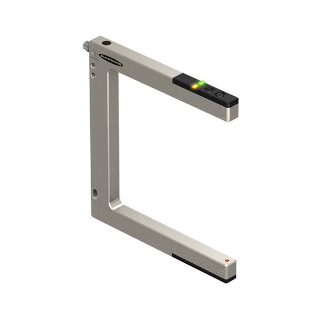
An easy-to-use, self-contained, opposed-mode sensor pair in a U-shaped housing
Rugged, sealed, die-cast metal housing is rated IEC IP67 (NEMA 6)
Easy and economical to mount; molded-in beam guides simplify beam placement
Eight slot widths from 10 mm to 220 mm for a wide variety of sensing applications
Current sourcing (PNP), current sinking (NPN), or bipolar (one NPN and one PNP)
output, depending on model
Fast 500-microsecond response time
10 V dc to 30 V dc supply voltage
Single-turn potentiometer sensitivity adjustment
Visible red beam
Selectable Light Operate (L.O.) or Dark Operate (D.O.) with sealed switch
WARNING: Not To Be Used for Personnel Protection
Never use this device as a sensing device for personnel protection. Doing so could lead to serious injury or death.
This device does not include the self-checking redundant circuitry necessary to allow its use in personnel safety
applications. A sensor failure or malfunction can cause either an energized or de-energized sensor output
condition.
Models
QD Models 1
SLM10P6Q
SLM10N6Q
SLM20P6Q
SLM20N6Q
SLM30P6Q
SLM30N6Q
SLM50P6Q
SLM50N6Q
SLM80P6Q
SLM80N6Q
SLM120P6Q
SLM120N6Q
SLM180P6Q
SLM180N6Q
SLM220P6Q
SLM220N6Q
Slot Width
10 mm (0.39 in)
20 mm (0.79 in)
30 mm (1.18 in)
50 mm (1.97 in)
80 mm (3.15 in)
120 mm (4.72 in)
180 mm (7.09 in)
220 mm (8.66 in)
Output Type
Cabled Models 2
Slot Width
PNP
SLM10B6
10 mm (0.39 in)
NPN
SLM20B6
20 mm (0.79 in)
PNP
SLM30B6
30 mm (1.18 in)
NPN
SLM50B6
50 mm (1.97 in)
PNP
SLM80B6
80 mm (3.15 in)
NPN
SLM120B6
120 mm (4.72 in)
PNP
SLM180B6
180 mm (7.09 in)
NPN
SLM220B6
220 mm (8.66 in)
Output Type
Bipolar (one NPN and
one PNP)
PNP
NPN
PNP
NPN
PNP
NPN
PNP
NPN
1 Integral 3-pin M8/Pico-style quick disconnect models are listed. Models with a quick disconnect require a mating cordset.
2 Integral 2 m (6.5 ft) unterminated cable models are listed.
• To order the 9 m (30 ft) PVC cable model, add the suffix "W/30" to the cabled model number. For example, SLM10B6 W/30.
• To order the 150 mm (6 in) PUR cable model with a 4-pin M12/Euro-style quick disconnect, add the suffix "QPMA" to the model number. For
example, SLM10B6QPMA.
• Models with a quick disconnect require a mating cordset.
Original Document
122703 Rev. G
3 April 2017
122703
�SLM Series Slot Sensors
Overview
The SLM Series Slot Sensor (sometimes called a “fork sensor”) comprises an opposed-mode emitter and its receiver inside a single
convenient housing.
Opposed-mode sensing is very reliable, and the single, self-contained housing provides easy installation, with no sensor alignment
required. In addition, molded-in arrows on the housing show at a glance the position of the beam, simplifying installation placement.
Applications include counting, gear tooth detection, edge detection, part sensing on conveyor rails and belts, position and orientation
verification, dimension verification, tool break monitoring, and level monitoring.
3 4
1.
2.
3.
4.
5.
6.
7.
8.
9.
2
1
5
6
7 (x2)
9
8
Output LED (amber)
Power on LED (green)
Dark/Light Operate select switch
Sensitivity potentiometer
Receiver aperture
Emitter aperture
Beam position arrows
Mounting hole (all models except SLM10 and SLM20)
Mounting holes (all models)
Wiring Diagrams
NPN
PNP
Bipolar
1
1
3
–
10–30 V dc
+
1
4
Load
+
10–30 V dc
–
3
4
Load
+
10–30 V dc
–
3
2
4
Key
Load
1.
2.
3.
4.
Brown
White
Blue
Black
Load
Configuring the Sensor
For the best results, place the objects to be detected midway between the emitter and receiver.
Adjusting the Sensitivity
Adjust the sensor’s sensitivity by turning the 270-degree-turn Sensitivity potentiometer with a small flat-blade screwdriver.
Apply power to the sensor and turn the potentiometer all the way clockwise (maximum gain). If the object to be sensed does not block
the beam at the maximum gain, turn the gain down a little at a time, testing with the object, until the object can be sensed reliably.
If adjusting the sensitivity with the potentiometer does not provide reliable object detection, investigate alternative sensing methods.
Selecting Light or Dark Operate
Select dark operate (D.O.) or light operate (L.O.) by turning the DO/LO selector switch to the desired setting using a small flat-blade
screwdriver.
If dark operate is selected, the output conducts when the receiver element does not see the emitted light (object is present). If light
operate is selected, the output conducts when the receiver element sees the emitted light (object is absent).
2
www.bannerengineering.com - Tel: +1-763-544-3164
P/N 122703 Rev. G
�SLM Series Slot Sensors
Specifications
Supply Voltage and Current
10 V dc to 30 V dc (10% max. ripple) at less than 25 mA, exclusive of load
Supply Protection Circuitry
Protected against reverse polarity and transient voltages
Construction
Housing: die-cast zinc with nickel plating
Endcaps: ABS
Optic windows: acrylic
Connections
Output Configuration
Cabled models: 2 m (6.5 ft) or 9 m (30 ft) 4-conductor, PVC-jacketed cable
Cabled and Euro-style QD models: Bipolar: One current sourcing (PNP) and one
Pico-style QD models: 3-pin, threaded integral QD connector
current sinking (NPN)
Euro-style QD models: 150 mm (6 in) PUR cable with 4-pin, threaded connector
Pico-style QD models: Current sourcing (PNP) or current sinking (NPN),
depending on model
Environmental Rating
IEC IP67; NEMA 6
Output Rating
100 mA with short circuit protection
OFF-state leakage current:
NPN: < 200 µA
PNP: < 10 μA
ON-state saturation voltage:
NPN: 1.6 V at 100 mA
PNP: 2.0 V at 100 mA
Required Overcurrent Protection
WARNING: Electrical connections must be made
by qualified personnel in accordance with local
and national electrical codes and regulations.
Output Protection Circuitry
Protected against output short-circuit and false pulse on power up
100 ms max. delay at power up; outputs do not conduct during this time
Output Response Time
500 microseconds
Overcurrent protection is required to be provided by end product application
per the supplied table.
Overcurrent protection may be provided with external fusing or via Current
Limiting, Class 2 Power Supply.
Supply wiring leads < 24 AWG shall not be spliced.
For additional product support, go to www.bannerengineering.com.
Supply Wiring (AWG)
Required Overcurrent Protection (Amps)
20
5.0
22
3.0
24
2.0
26
1.0
28
0.8
30
0.5
Repeatability
95 microseconds
Operating Conditions
−20 °C to +60 °C (−4 °F to +140 °F)
95% at +55 °C maximum relative humidity (non-condensing)
Slot Opening
10 mm, 20 mm, 30 mm, 50 mm, 80 mm, 120 mm, 180 mm, or 220 mm
(depending on model); beam is 5 mm (0.2 in) from outer edge
Adjustments
1-turn potentiometer sensitivity adjustment
Light/dark operate selection switch
Certifications
Indicators
Two LED Indicators: Power (green) and Output (amber)
Green on: Power on
Green flashing: Sensor short circuit
Amber on: Output is activated
E224071
SLM10
SLM20
SLM30
SLM50
SLM80
SLM120
SLM180
SLM220
Minimum object detection at
maximum gain 3
1.00 mm
(0.040 in)
1.25 mm
(0.050 in)
1.50 mm
(0.060 in)
1.65 mm
(0.065 in)
1.80 mm
(0.070 in)
1.80 mm
(0.070 in)
1.80 mm
(0.070 in)
2.40 mm
(0.095 in)
Minimum object detection at 2
times excess gain3
0.30 mm
(0.012 in)
0.30 mm
(0.012 in)
0.40 mm
(0.016 in)
0.60 mm
(0.024 in)
0.75 mm
(0.030 in)
0.90 mm
(0.035 in)
0.90 mm
(0.035 in)
1.00 mm
(0.039 in)
Hysteresis4
0.10 mm
(0.004 in)
0.10 mm
(0.004 in)
0.10 mm
(0.004 in)
0.10 mm
(0.004 in)
0.20 mm
(0.008 in)
0.20 mm
(0.008 in)
0.20 mm
(0.008 in)
0.20 mm
(0.008 in)
Repeatability 5
0.02 mm
(0.001 in)
0.02 mm
(0.001 in)
0.02 mm
(0.001 in)
0.04 mm
(0.002 in)
0.06 mm
(0.002 in)
0.08 mm
(0.003 in)
0.08 mm
(0.003 in)
0.08 mm
(0.003 in)
3 The smallest diameter rod that can be detected when passed slowly through sensing beam. Minimum object detection is measured midway between the emitter
and receiver. For best results, place the object to be detected in the midway position when possible. The minimum object detection size may increase if the
object is very close to the receiver side.
4 The distance an object must move to toggle between output OFF and output ON state.
5 The variation in switching distance for a standard target at controlled sensing conditions.
P/N 122703 Rev. G
www.bannerengineering.com - Tel: +1-763-544-3164
3
�SLM Series Slot Sensors
Dimensions
QD
Models
Cabled
Models
24.6
[0.97"]
5.0
[0.20"]
Overall Width
34.9
[1.37"]
14.1
[0.56"]
Slot Width
Slot
Depth
9.0
[0.35"]
Overall
Depth
D
5.0
[0.20"]
16.5
[0.65"]
3X Ø 4.5
[Ø 0.18"]
A
1.0
[0.04"]
5.0
[0.20"]
4.0 [0.16"]
8.0 [0.31"]
20.0 [0.79"]*
C
6.0
[0.24"]
12.0
[0.47"]
B
2X 15.0
[0.59"]
4X M4 x 0.7 mm threads - 6.5 mm deep
Hardware: 2X M4 x 25 socket head cap screws
2X M4 nuts with captured lock washers
Hex key
Max. torque 2.8 Nm (25 in-lbs)
*Model SLM10.. measures 18.0 [0.71"]
All measurements are listed in millimeters [inches], unless noted otherwise.
Models
Slot Width
Slot Depth
SLM10
10 mm (0.39")
42 mm (1.65")
SLM20
20 mm (0.79")
52 mm (2.05")
60.8 mm
(2.39")
Overall Width
A
B
Side Mount
Back Mount
n/a
SLM30
30 mm (1.18")
SLM50
50 mm (1.97")
82 mm (3.23")
30 mm (1.18")
SLM80
80 mm (3.15")
112 mm (4.41")
60 mm (2.36")
SLM120
120 mm (4.72")
SLM180
180 mm (7.09")
SLM220
220 mm (8.66")
4
62 mm (2.44")
Overall Depth
80 mm (3.15")
152 mm (5.98")
120.7 mm
(4.75")
212 mm (8.35")
252 mm (9.92")
140 mm
(5.51")
n/a
C
D
n/a
70 mm
(2.76")
10 mm (0.39")
15 mm (0.59")
33.5 mm (1.32")
48.5 mm (1.91")
100 mm (3.94")
30 mm (1.18")
46 mm (1.81")
160 mm (6.30")
70 mm (2.76")
56 mm (2.20")
200 mm (7.87")
90 mm (3.54")
66 mm (2.60")
www.bannerengineering.com - Tel: +1-763-544-3164
130 mm
(5.12")
P/N 122703 Rev. G
�SLM Series Slot Sensors
Accessories
3-Pin Threaded M8/Pico-Style Cordsets
Model
Length
PKG3M-2
2 m (6.56 ft)
PKG3M-5
5 m (16.40 ft)
PKG3M-7
7 m (22.97 ft)
PKG3M-9
9 m (29.53 ft)
PKG3M-10
10 m (32.81 ft)
PKW3M-2
2 m (6.56 ft)
PKW3M-5
5 m (16.40 ft)
Style
Dimensions
35 Typ.
Straight
ø 9.5
M8 x 1
4
1
3
28 Typ.
9 m (29.53 ft)
1 = Brown
3 = Blue
4 = Black
20 Typ.
Right-Angle
PKW3M-9
Pinout (Female)
M8 x 1
ø 9.5
3-Pin Snap/Pico-Style Cordsets
Model
Length
Style
Dimensions
Pinout (Female)
ø 10 mm max.
(0.4")
PKG3Z-2
2 m (6.56 ft)
Straight
4
28 mm max.
(1.1")
PKW3-2
2 m (6.56 ft)
1
3
25 mm max.
(1.0")
1 = Brown
3 = Blue
4 = Black
20 mm
(0.8")
Right-Angle
ø 12 mm max.
(0.5")
4-Pin Threaded M12/Euro-Style Cordsets
Model
Length
MQDC-406
1.83 m (6 ft)
MQDC-415
4.57 m (15 ft)
MQDC-430
9.14 m (30 ft)
MQDC-450
15.2 m (50 ft)
MQDC-406RA
1.83 m (6 ft)
MQDC-415RA
4.57 m (15 ft)
MQDC-430RA
9.14 m (30 ft)
Style
Dimensions
44 Typ.
Straight
M12 x 1
ø 14.5
P/N 122703 Rev. G
15.2 m (50 ft)
1
4
32 Typ.
[1.26"]
30 Typ.
[1.18"]
Right-Angle
MQDC-450RA
Pinout (Female)
2
3
1 = Brown
2 = White
3 = Blue
4 = Black
M12 x 1
ø 14.5 [0.57"]
www.bannerengineering.com - Tel: +1-763-544-3164
5
�SLM Series Slot Sensors
Banner Engineering Corp. Limited Warranty
Banner Engineering Corp. warrants its products to be free from defects in material and workmanship for one year following the date of shipment. Banner Engineering Corp. will repair or
replace, free of charge, any product of its manufacture which, at the time it is returned to the factory, is found to have been defective during the warranty period. This warranty does not cover
damage or liability for misuse, abuse, or the improper application or installation of the Banner product.
THIS LIMITED WARRANTY IS EXCLUSIVE AND IN LIEU OF ALL OTHER WARRANTIES WHETHER EXPRESS OR IMPLIED (INCLUDING, WITHOUT LIMITATION, ANY WARRANTY OF
MERCHANTABILITY OR FITNESS FOR A PARTICULAR PURPOSE), AND WHETHER ARISING UNDER COURSE OF PERFORMANCE, COURSE OF DEALING OR TRADE USAGE.
This Warranty is exclusive and limited to repair or, at the discretion of Banner Engineering Corp., replacement. IN NO EVENT SHALL BANNER ENGINEERING CORP. BE LIABLE TO BUYER OR ANY
OTHER PERSON OR ENTITY FOR ANY EXTRA COSTS, EXPENSES, LOSSES, LOSS OF PROFITS, OR ANY INCIDENTAL, CONSEQUENTIAL OR SPECIAL DAMAGES RESULTING FROM ANY PRODUCT
DEFECT OR FROM THE USE OR INABILITY TO USE THE PRODUCT, WHETHER ARISING IN CONTRACT OR WARRANTY, STATUTE, TORT, STRICT LIABILITY, NEGLIGENCE, OR OTHERWISE.
Banner Engineering Corp. reserves the right to change, modify or improve the design of the product without assuming any obligations or liabilities relating to any product previously
manufactured by Banner Engineering Corp. Any misuse, abuse, or improper application or installation of this product or use of the product for personal protection applications when the
product is identified as not intended for such purposes will void the product warranty. Any modifications to this product without prior express approval by Banner Engineering Corp will void the
product warranties. All specifications published in this document are subject to change; Banner reserves the right to modify product specifications or update documentation at any time.
Specifications and product information in English supersede that which is provided in any other language. For the most recent version of any documentation, refer to:
www.bannerengineering.com.
© Banner Engineering Corp. All rights reserved
�