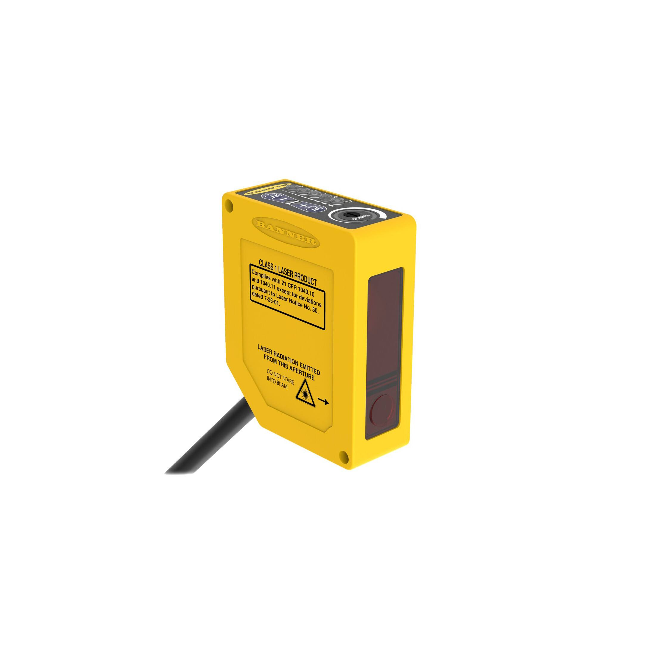
Q60LAF Series Laser Adjustable-Field Sensors
Datasheet
Long-Range Self-Contained Adjustable-Field Laser Sensors
•
•
•
•
•
•
•
Long-range adjustable-field background suppression sensor detects objects within a
defined sensing field, and ignores objects located beyond the sensing field cutoff
Powerful visible red laser sensing beam, class 1 and class 2 models available
Two-turn, logarithmic cutoff point adjustment for easy setting of cutoff point at long
range; rotating pointer indicates relative cutoff point setting
Easy push-button or remote programming of light/dark operate and output timing;
continuous status indicators verify all settings at a glance
Output ON and/or OFF delays adjustable from 8 milliseconds to 16 seconds
Tough ABS/polycarbonate blend housing is rated IEC IP67; NEMA 6
Models available for 10 to 30 V dc operation or universal voltage (12 to 250 V dc or 24
to 250 V ac, 50/60 Hz)
WARNING: Not To Be Used for Personnel Protection
Never use this device as a sensing device for personnel protection. Doing so could lead to serious injury or
death. This device does not include the self-checking redundant circuitry necessary to allow its use in personnel
safety applications. A sensor failure or malfunction can cause either an energized or de-energized sensor output
condition.
Models
Class 1 Laser
Models
Cutoff Point
Cable
Q60BB6LAF1400
5-wire 2 m (6.5 ft)
Q60BB6LAF1400Q
5-pin Euro-style QD
Q60BB6LAF1400QP
5-pin Euro-style QD 150 mm
(6 in)
Q60VR3LAF1400
Adjustable:
200 mm to 1400 mm (8 in to
55 in)
Q60VR3LAF1400Q1
Class 2 Laser
Models
Cutoff Point
E/M Relay (SPDT), normally
closed and normally open
contacts
Supply Voltage
Output Type
10 V dc to 30 V dc
Bipolar NPN/PNP
5-pin Euro-style QD
Q60BB6LAF2000QP
5-pin Euro-style QD 150
mm (6 in)
Q60VR3LAF2000Q1
Bipolar NPN/PNP
Cable1
Q60BB6LAF2000Q
Q60VR3LAF2000
10 V dc to 30 V dc
4-pin Micro-style QD
5-wire 2 m (6.5 ft)
200 mm to 2000 mm (8 in to
80 in)
Output Type
Universal Voltage
12 V dc to 250 V dc
or
24 V ac to 250 V ac
5-wire 2 m (6.5 ft)
Q60BB6LAF2000
Adjustable:
Supply Voltage
5-wire 2 m (6.5 ft)
4-pin Micro-style QD
Universal Voltage
12 V dc to 250 V dc
or
24 V ac to 250 V ac
E/M Relay (SPST), normally
open contact
E/M Relay (SPDT), normally
closed and normally open
contacts
E/M Relay (SPST), normally
open contact
1 To order the 9 m (30 ft) PVC cable model, add the suffix "W/30" to the cabled model number. For example, Q60BB6LAF1400 W/30. Models
with a quick disconnect require a mating cordset.
Original Document
114348 Rev. A
10 February 2017
114348
�Q60LAF Series Laser Adjustable-Field Sensors
Overview
The Q60LAF sensor is a full-featured adjustable-field sensor. These adjustable-field sensors are able to detect objects of relatively low
reflectivity, while ignoring other objects in the background (beyond the cutoff point). The cutoff distance is mechanically adjustable,
using the 2-turn adjustment screw on the top of the sensor. A rotating pointer indicates the relative cutoff position. The indicator moves
clockwise to show increasing distance.
The collimated laser emitter produces a small, bright spot, allowing easy alignment and precision sensing of relatively small objects at
long range.
Two push buttons (ON Delay and OFF Delay) are used to set the output delay options, to toggle between light and dark operate modes
and to lock out the push buttons for security purposes. These functions also may be accomplished using the remote wire (available on
some models).
Seven LED indicators show, during RUN mode, the sensor configuration and operating status. During Delay Configuration, 5 of the LEDs
combine to form a single light bar that indicates relative ON or OFF delay time.
Note: When an object approaches from the side, the most reliable sensing usually occurs when the line of approach
is parallel to the sensing axis.
Note: Sensing at closer than the minimum specified range is not guaranteed.
Features and Indicators
Note: Outputs are active during on/off timing selection mode.
ON Delay
Steady Green: Run mode, ON delay is active
Flashing Green: ON Delay Selection mode is active
OFF Delay
Steady Green: Run mode, OFF delay is active
Flashing Green: OFF Delay Selection mode is active
5-Segment Light Bar
Indicates relative delay time during ON or OFF Delay
Selection modes
Output Indicator
Steady Amber: Outputs are conducting
Steady Green: During ON/OFF Delay Selection modes
Dark Operate Indicator
Steady Green: Dark Operate is selected
Lockout Indicator
Steady Green: Buttons are locked out
Light Operate Indicator
Steady Green: Light Operate is selected
Signal Indicator
Steady Green: Sensor is receiving signal
Flashing Green: Marginal signal (1.0 to 2.25 excess
gain)
ON/OFF Delay Push
Buttons and Indicators
Cutoff Adjustment Screw
Light Sensed Indicator
Light Operate Selected
Push Button
Lockout Indicator
Dark Operate Selected
Output Conducting
(Bi-color Amber/Green)
The indicators, above right, also function as a 5segment light gar during delay selection modes
Adjustable-Field Sensing—Theory of Operation
The Q60LAF compares the reflections of its emitted light beam (E) from an object back to the sensor’s two differently-aimed detectors
R1 and R2 (see Figure 1 on page 3). If the near detector (R1) light signal is stronger than the far detector (R2) light signal (see object
A, closer than the cutoff distance), the sensor responds to the object. If the far detector (R2) light signal is stronger than the near
detector (R1) light signal (see object B, object beyond the cutoff distance), the sensor ignores the object.
The cutoff distance for these sensors is adjustable. Objects lying beyond the cutoff distance are ignored, even if they are highly
reflective. However, it is possible to falsely detect a background object, under certain conditions (see Background Reflectivity and
Placement on page 4).
2
www.bannerengineering.com - Tel: +1-763-544-3164
P/N 114348 Rev. A
�Q60LAF Series Laser Adjustable-Field Sensors
Cutoff
Distance
Receiver
Elements
Object B
or
Background
Object
A
Near
Detector R1
Lenses
Receiver
Elements
Far
Detector R2
Emitter
E
Sensing
Axis
Sensing
Range
Figure 1. Adjustable field sensing concept
Figure 2. Sensing Axis
In the drawings and information provided in this document, the letters E, R1, and R2 identify how the sensor’s three optical elements
(Emitter “E”, Near Detector “R1”, and Far Detector “R2”) line up across the face of the sensor. The location of these elements defines
the sensing axis (see Figure 2 on page 3). The sensing axis becomes important in certain situations, such as those illustrated in Figure 7
on page 5 and Figure 8 on page 5.
Installation
Wiring Diagrams
Q60BB6xx(Q)
Q60VR3xx
Cabled and QD Models, 10 to 30 V dc
Cabled Model, 24 to 250 V ac (50/60Hz) or 12 to 250 V
dc
1
+
10-30V dc
–
3
2
4
3
2
5
Load
4
Load
5
1
24 - 250V ac or 12 - 250V dc
N.C.
C
N.O.
Key
1 = Brown
2 = White
3 = Blue
4 = Black
5 = Gray
Remote
Program
Q60VR3xxQ1
QD Model, 24 to 250 V ac (50/60Hz) or 12 to 250 V dc
Key
1
24-250V ac
or 12-250V dc*
2
3
4
N.O.
C
1 = Red/Black
2 = Red/White
3 = Red
4 = Green
3 A max. load
*NOTE: Connection of dc power is without regard to polarity.
Set the Cutoff Distance
The cutoff distance for Q60LAF sensors can be adjusted between 200 mm and 1400 mm (8 in to 55 in) for Class 1 laser models, and
between 200 mm and 2000 mm (8 in to 80 in) for Class 2 laser models.
P/N 114348 Rev. A
www.bannerengineering.com - Tel: +1-763-544-3164
3
�Q60LAF Series Laser Adjustable-Field Sensors
Target
Background
Increas
ing
Dis
To maximize contrast, position the lightest possible background to be used, at the closest position it will come to the sensor during use.
Using a small screwdriver in the adjustment screw, adjust the cutoff distance until the threshold is reached and the green Light Sensed
indicator changes state. If the indicator never turns ON, the background is beyond the maximum sensing cutoff and will be ignored.
Note the position of the rotating cutoff position indicator at this position. Then repeat the procedure, using the darkest target, placed in
its most distant position for sensing. Adjust the cutoff so that the indicator is midway between the two positions.
ce
tan
Farthest Target Object
RANGE
R1
R2
ON
DELAY
E
Set Cutoff Midway
Between
Closest Background
DO
LO
SIG
Cutoff
Distance
Figure 3. Set the cutoff distance approximately midway between the
farthest target and the closest background
OFF
DELAY
Figure 4. Setting the cutoff distance
Note: Setting the cutoff distance adjustment screw to its maximum clockwise position places the receiver lens
directly in front of the receiver elements and results in the Q60 performing as a long-range diffuse sensor.
Sensing Reliability
For highest sensitivity, the sensor-to-object distance should be such that the object will be sensed at or near the point of maximum
excess gain. The excess gain curves show excess gain versus sensing distance for 200 mm, 1200 mm, and 2 m cutoffs. Maximum excess
gain for a 200 mm cutoff occurs at a lens-to-object distance of about 150 mm, and for a 2 m cutoff, at about 500 mm. The background
must be placed beyond the cutoff distance. Following these two guidelines makes it possible to detect objects of low reflectivity, even
against close-in reflective backgrounds.
Background Reflectivity and Placement
Avoid mirror-like backgrounds that produce specular reflections. A false sensor response occurs if a background surface reflects the
sensor's light more to the near detector (R1) than to the far detector (R2). The result is a false ON condition (Figure 5 on page 4).
Correct this problem by using a diffusely reflective (matte) background, or angling either the sensor or the background (in any plane) so
the background does not reflect light back to the sensor (Figure 6 on page 4). Position the background as far beyond the cutoff
distance as possible.
An object beyond the cutoff distance, either stationary (and when positioned as shown in Figure 7 on page 5), or moving past the
face of the sensor in a direction perpendicular to the sensing axis, may cause unwanted triggering of the sensor if more light is reflected
to the near detector than to the far detector. Correct the problem by rotating the sensor 90° (Figure 8 on page 5). The object then
reflects the R1 and R2 fields equally, resulting in no false triggering. A better solution, if possible, may be to reposition the object or the
sensor.
Sensing
Field
Core of
Emitted
Beam
R1
R2
E
Reflective
Background
E = Emitter
R1 = Near Detector
R2 = Far Detector
4
Core of
Emitted
Beam
E = Emitter
R1 = Near Detector
R2 = Far Detector
Figure 5. Reflective Background - Problem
Cutoff
Distance
Reflective
Background
Strong
Direct
Reflection
to R1
R1
R2
E
Sensing
Field
Cutoff
Distance
Strong
Direct
Reflection
Away From
Sensor
Figure 6. Reflective Background - Solution
www.bannerengineering.com - Tel: +1-763-544-3164
P/N 114348 Rev. A
�Q60LAF Series Laser Adjustable-Field Sensors
DO
LO
SIG
Cutoff
Distance
ON
DELAY
DELAY
RANGE
E, R1, R2
OFF
R1
R2
E
Sensing
Field
Sensing
Field
A reflective background object in this position or moving across the sensor face
in this axis and direction may cause a false sensor response.
A reflective background object in this position or moving across the sensor face
in this axis is ignored.
Figure 7. Object Beyond Cutoff - Problem
Figure 8. Object Beyond Cutoff - Solution
Color Sensitivity
The effects of object reflectivity on cutoff distance, though small, may be important for some applications. It is expected that at any
given cutoff setting, the actual cutoff distance for lower reflectance targets is slightly shorter than for higher reflectance targets. This
behavior is known as color sensitivity.
These excess gain curves were generated using a white test card of 90% reflectance. Objects with reflectivity of less than 90% reflect
less light back to the sensor, and thus require proportionately more excess gain in order to be sensed with the same reliability as more
reflective objects. When sensing an object of very low reflectivity, it may be especially important to sense it at or near the distance of
maximum excess gain.
The percentage of deviation indicates a change in the cutoff point for either 18% gray or 6% black targets, relative to the cutoff point set
for a 90% reflective white test card.
For example, the cutoff point decreases 10% for a 6% reflectance black target when the cutoff point is adjusted for 1700 mm (67 in)
using a 90% reflectance white test card. In other words, the cutoff point for the black target is 1530 mm (60 in) for this setting.
Minimum Range vs. Cutoff Setting*
Cutoff Point Deviation
300
0
Class 1
-1
-2
Minimum Range (mm)
250
Percent Deviation
-3
-4
-5
-6
-7
200
150
100
50
-8
-9
-10
-12
200
Class 2
0
200
400
600
400
800 1000 1200 1400 1600 1800 2000
Cutoff Setting (90% White Card)
600
800
1000 1200 1400 1600 1800 2000
Cutoff Distance (mm) with 90% White Card
*NOTE: Minimum range is independent of target reflectivity
Figure 9. Cutoff Point Deviation
Figure 10. Q60 Minium Range Versus Cutoff Setting
Hysteresis (% of Cutoff)
Hysteresis
6.0
4.0
Class 1 Laser 18% Gray Card
6% Black Card
2.0
Class 2 Laser 18% Gray Card
6% Black Card
0
200
400
600
800
1000 1200 1400
1600 1800 2000
Cutoff Setting (mm) with 90% White Card
Figure 11. Hysteresis
P/N 114348 Rev. A
www.bannerengineering.com - Tel: +1-763-544-3164
5
�Q60LAF Series Laser Adjustable-Field Sensors
Configuring a Sensor
Set the Output Delay
The output of the Q60LAF sensor may be delayed between 0.008 and Major increments, displayed by a single full-intensity LED, are
16 seconds, in any of 72 increments. Delay is indicated on the 5shown:
segment light bar using single LED segments or combinations of them,
Step #
Delay Time
LED Status
in varying stages of intensity.
DO
DO
DO
DO
DO
DO
16 seconds
LO
72
SIG
4.0 seconds
LO
56
SIG
1.00 second
LO
40
SIG
0.250 second
LO
24
SIG
0.062 second
LO
8
SIG
No Delay
LO
0
SIG
To set a delay, single-click the appropriate button or pulse the remote
wire to enable the process (as described in the following procedures).
Then use the + or – button or the appropriate remote wire pulse
procedure to increase or decrease the delay (single-click adjusts the
delay by one step at a time, and holding the button in provides a rapid
increase/decrease).
Increase or Decrease the ON Delay
T = 40 – 800 ms
Press and Hold > 800 ms unless otherwise noted
Increase the ON Delay—4-second time-out
Enter ON Delay Setup
Enable Delay Increment
Single-Click
Push Button
ON
DELAY
–
+
Step Decrement
>800 ms
Rapid Decrement
Press and Hold
Single-Click
ON
–
+
DELAY
DELAY
T >800 ms
OFF
ON
DELAY
–
+
DELAY
T T T >800 ms
DELAY
T >800 ms
OFF
ON
DELAY
–
+
DELAY
OFF
T >800 ms
Press and Hold
OFF
N/A
ON
Single-Click
Push Button
Remote Input
Enable Delay Decrement
DELAY
Decrease the ON Delay—4-second time-out
Enter ON Delay Setup
–
DELAY
T >800 ms
+
OFF
ON
T >800 ms
Rapid Increment
Single-Click
N/A
DELAY
+
–
DELAY
OFF
Remote Input
Step Increment
>800 ms
Increase or Decrease the OFF Delay
T = 40 – 800 ms
Press and Hold > 800 ms unless otherwise noted
6
www.bannerengineering.com - Tel: +1-763-544-3164
P/N 114348 Rev. A
�Q60LAF Series Laser Adjustable-Field Sensors
Increase the OFF Delay—4-second time-out
Enter OFF Delay Setup
Enable Delay Increment
Single-Click
Push Button
ON
DELAY
–
+
>800 ms
Rapid Decrement
Press and Hold
Single-Click
ON
–
+
DELAY
DELAY
T >800 ms
OFF
ON
DELAY
–
+
T T T >800 ms
DELAY
Step Decrement
DELAY
ON
T T T >800 ms
Press and Hold
OFF
T >800 ms
OFF
DELAY
+
–
DELAY
OFF
Remote Input
N/A
ON
Single-Click
Push Button
DELAY
Enable Delay Decrement
–
Decrease the OFF Delay—4-second time-out
Enter OFF Delay Setup
+
ON
DELAY
OFF
DELAY
T >800 ms
T T T >800 ms
Rapid Increment
Single-Click
N/A
+
–
DELAY
OFF
Remote Input
Step Increment
>800 ms
Select Light Operate or Dark Operate
Select Light Operate or Dark Operate mode using the two push buttons or a triple-pulse of the remote line to toggle between the
selections.
LO/DO Toggle
Concurrent Triple-Click
T
ON
DELAY
–
T
+
OFF
Remote Input
DELAY
Push Button
T
T
T
Lock the Push Buttons
For security, the push buttons can be locked out using either the remote line or the push buttons themselves.
Push Button Lockout Toggle
Concurrent Quad-Click
ON
DELAY
–
+
DELAY
Remote Input
OFF
Push Button
T T T T T T T >800 ms
Enable or Disable the Laser
The laser is disabled after remote line is held low for 800 ms and will remain disabled until remote line is released.
Note: 500 ms maximum delay after laser is enabled; outputs will default to “No Light” state.
Disable the Laser
Push Button
Remote Input
P/N 114348 Rev. A
Not available
>800 ms
www.bannerengineering.com - Tel: +1-763-544-3164
7
�Q60LAF Series Laser Adjustable-Field Sensors
Laser Description and Safety Information
CAUTION: Do Not Disassemble for Repair
This device contains no user-serviceable components. Do not
attempt to disassemble for repair. Use of controls or adjustments or
performance of procedures other than those specified herein may
result in hazardous radiation exposure. A defective unit must be
returned to the manufacturer.
Aperture
Ø 3.76 mm
(0.148")
16.76 mm
(0.66")
12.5 mm
(0.49")
Figure 12. Laser Aperture Location
Class 1 Lasers
Class 1 lasers are lasers that are safe under reasonably foreseeable conditions of operation,
including the use of optical instruments for intrabeam viewing.
Reference IEC 60825-1:2001, Section 8.2.
Class 2 Lasers
Class 2 lasers are lasers that emit visible radiation in the wavelength range from 400 nm to
700 nm, where eye protection is normally afforded by aversion responses, including the
blink reflex. This reaction may be expected to provide adequate protection under
reasonably foreseeable conditions of operation, including the use of optical instruments for
intrabeam viewing.
Reference IEC 60825-1:2001, Section 8.2.
Class 2 Laser Safety Notes
Low-power lasers are, by definition, incapable of causing eye injury within the duration of a
blink (aversion response) of 0.25 seconds. They also must emit only visible wavelengths (400
to 700 nm). Therefore, an ocular hazard may exist only if individuals overcome their natural
aversion to bright light and stare directly into the laser beam.
CLASS 2
LASER PRODUCT
Pulse Power < 2.6mW 650-670
nm, 2kHz, 15.5 uS Pulse.
Complies to 21 CFR 1040.01 &
EN60825-1:2001 except for
deviations pursuant to laser
notice No. 50, dated 7-26-01.
LASER RADIATION EMITTED
FROM THIS APPERTURE
DO NOT STARE
INTO BEAM
For Safe Laser Use (Class 1 or Class 2):
•
•
•
•
8
Do not stare at the laser.
Do not point the laser at a person’s eye.
Mount open laser beam paths either above or below eye level, where practical.
Terminate the beam emitted by the laser product at the end of its useful path.
www.bannerengineering.com - Tel: +1-763-544-3164
P/N 114348 Rev. A
�Q60LAF Series Laser Adjustable-Field Sensors
Specifications
Supply Voltage and Current
Q60BB6LAF models: 10 to 30 V dc (10% maximum ripple) at less than 50 mA
exclusive of load
Q60VR3LAF Universal models: 12 to 250 V dc or 24 to 250 V ac, 50/60 Hz
Input power: 1.5 W maximum
Supply Protection Circuitry
Protected against reverse polarity and transient voltages
The dc wiring for model Q60VR3 is without regard to polarity
Output Configuration
Q60BB6LAF models: Bipolar; one NPN (current sinking) and one PNP (current
sourcing) open-collector transistor
Q60VR3LAF cabled model: E/M Relay (SPDT), normally closed and normally
open contacts
Q60VR3LAFQ1 (QD) model: E/M Relay (SPST), normally open contact
Output Rating—Q60BB6LAF models
150 mA maximum each output @ 25 °C
Off-state leakage current: < 5 μA @ 30 V dc
Output saturation NPN: < 200 mV @ 10 mA and < 1 V @150 mA
Output saturation PNP: < 1 V at 10 mA; < 1.5 V at 150 mA
Adjustments
Slotted, geared, 2-turn, cutoff range adjustment screw (mechanical stops on
both ends of travel)
2 momentary push buttons: ON Delay (+) and OFF Delay (–); DC models also
have a remote program wire
ON Delay select: 8 ms to 16 seconds
OFF Delay select: 8 ms to 16 seconds
LO/DO select
Push button lockout for security
Laser Enable/Disable (remote wire only)
Construction
Housing: ABS polycarbonate blend
Lens: Acrylic
Environmental Rating
IEC IP67; NEMA 6
Connections
Q60BB6LAF models: 2 m (6.5 ft) or 9 m (30 ft) attached cable, 5-pin Euro-style
integral QD, or 5-pin Euro-style 150 mm (6 in) QD
Q60VR3LAF Universal models: 2 m (6.5 ft) or 9 m (30 ft) attached cable, or 5pin Micro-style 150 mm (6 in) QD
Output Rating—Q60VR3LAF Universal models
Minimum voltage and current: 5 V dc, 10 mA
Operating Conditions
Mechanical life of relay: 50,000,000 operations
Temperature:
Electrical life of relay at full resistive load: 100,000 operations
Q60BB6LAF models: −10 °C to +50 °C (+14 °F to +122 °F)
Maximum switching power (resistive load):
Q60VR3LAF Universal models: −10 °C to +45 °C (+14 °F to +113 °F)
Cabled models: 1250 VA, 150 W
90% at +50 °C maximum relative humidity (non-condensing)
QD models: 750 VA, 90 W
Maximum switching voltage (resistive load):
Required Overcurrent Protection
Cabled models: 250 V ac, 125 V dc
WARNING: Electrical connections must be made
QD models: 250 V ac, 125 V dc
by qualified personnel in accordance with local
Maximum switching current (resistive load):
and national electrical codes and regulations.
Cabled models: 5 A @ 250 V ac, 5 A @ 30 V dc derated to 200 mA @ 125 V
dc
Overcurrent protection is required to be provided by end product application
QD models: 3 A @ 250 V ac, 3 A @ 30 V dc derated to 200 mA @ 125 V dc
per the supplied table.
Overcurrent protection may be provided with external fusing or via Current
Output Protection Circuitry
Limiting, Class 2 Power Supply.
Q60BB6LAF models: Protected against continuous overload or short circuit of
Supply wiring leads < 24 AWG shall not be spliced.
outputs
For additional product support, go to www.bannerengineering.com.
All models: Protected against false pulse on power-up
Note: 1 second maximum delay at power up
(outputs do not conduct during this time)
Supply Wiring (AWG)
Required Overcurrent Protection (Amps)
20
5.0
22
3.0
24
2.0
26
1.0
28
0.8
30
0.5
Output Response Time
Q60BB6LAF models: 2 milliseconds ON and OFF
Q60VR3LAF Universal models: 15 milliseconds ON and OFF
Repeatability
500 microseconds
Sensing Hysteresis
See Figure 11 on page 5
Laser Characteristics
Spot Size: approximately 4 × 2 mm throughout range (collimated beam)
Angle of Divergence: 5 milliradians
Certifications
Note: Contact Banner Engineering for a custom
laser spot size.
P/N 114348 Rev. A
www.bannerengineering.com - Tel: +1-763-544-3164
9
�Q60LAF Series Laser Adjustable-Field Sensors
Dimensions
15.2 mm
(0.60")
4.0 mm
(0.16")
4.9 mm
(0.19")
–
DELAY
OFF
LO
SIG
+
ON
DO
RANGE
25.0 mm
(0.98")
DELAY
60.0 mm
(2.36")
52.0 mm
(2.05")
4.0 mm
(0.16")
2x ø4.2 mm
(0.17")
14.0 mm
(0.55")
Q60BB6AFV200
75.0 mm
(2.95")
52.0 mm
(2.05")
bn
67.0 mm
(2.64")
bu
wh
bk
Q60BB6AFV200Q
bn
+
10-30V dc
–
+
10-30V dc
–
bu
wh
Load
Load
bk
Load
gy
Load
gy
Remote Teach
M3 hardware is included
Remote Teach
17.0 mm
(0.67")
77.6 mm
(3.06")
Performance Curves
Performance is based on a 90% reflectance white test card.
Class 1 Laser Models—Excess Gain at 200 mm and 1200 mm
Cutoff
Class 2 Laser Models—Excess Gain at 1200mm and 2000 mm
Cutoff
1000
1000
100
GAIN
G
A
I
N
at 1200 mm
10
1
10 mm
(0.396")
EXCESS
E
X
C
E
S
S
at 200 mm
100 mm
(3.96")
1000 mm
(39.6")
10000 mm
(396")
at 1200 mm
at 2000 mm
100
10
1
10 mm
(0.396")
1000 mm
(39.6")
10000 mm
(396")
DISTANCE
DISTANCE
10
100 mm
(3.96")
www.bannerengineering.com - Tel: +1-763-544-3164
P/N 114348 Rev. A
�Q60LAF Series Laser Adjustable-Field Sensors
Accessories
Cordsets
4-Pin Micro-Style Cordsets
Model
Length
MQAC-406
1.83 m (6 ft)
MQAC-415
4.57 m (15 ft)
Style
Dimensions
Pinout (Female)
42 Typ.
Straight
MQAC-430
1/2-20 UNF-28
ø 14.5
9.14 m (30 ft)
MQAC-406RA
1.83 m (6 ft)
MQAC-415RA
4.57 m (15 ft)
2
32 Typ
9.14 m (30 ft)
4
1
1 = Red/Black
2 = Red/White
3 = Red
4 = Green
28 Typ
Right-Angle
MQAC-430RA
3
1/2-20 UNF-28
ø 14.5
5-Pin Threaded M12/Euro-Style Cordsets—Single Ended
Model
MQDC1-501.5
Length
Style
Dimensions
0.50 m (1.5 ft)
MQDC1-506
1.83 m (6 ft)
MQDC1-515
4.57 m (15 ft)
MQDC1-530
9.14 m (30 ft)
MQDC1-506RA
1.83 m (6 ft)
MQDC1-515RA
4.57 m (15 ft)
44 Typ.
Straight
M12 x 1
ø 14.5
2
1
3
4
32 Typ.
[1.26"]
30 Typ.
[1.18"]
Right-Angle
MQDC1-530RA
Pinout (Female)
9.14 m (30 ft)
5
1 = Brown
2 = White
3 = Blue
4 = Black
5 = Gray
M12 x 1
ø 14.5 [0.57"]
Brackets
60
SMBQ60
• Right-angle bracket
• 14-ga., 304 Stainless Steel
ø3.8
82
ø4.5
22
P/N 114348 Rev. A
www.bannerengineering.com - Tel: +1-763-544-3164
11
�Q60LAF Series Laser Adjustable-Field Sensors
Banner Engineering Corp. Limited Warranty
Banner Engineering Corp. warrants its products to be free from defects in material and workmanship for one year following the date of shipment. Banner Engineering Corp. will repair or
replace, free of charge, any product of its manufacture which, at the time it is returned to the factory, is found to have been defective during the warranty period. This warranty does not cover
damage or liability for misuse, abuse, or the improper application or installation of the Banner product.
THIS LIMITED WARRANTY IS EXCLUSIVE AND IN LIEU OF ALL OTHER WARRANTIES WHETHER EXPRESS OR IMPLIED (INCLUDING, WITHOUT LIMITATION, ANY WARRANTY OF
MERCHANTABILITY OR FITNESS FOR A PARTICULAR PURPOSE), AND WHETHER ARISING UNDER COURSE OF PERFORMANCE, COURSE OF DEALING OR TRADE USAGE.
This Warranty is exclusive and limited to repair or, at the discretion of Banner Engineering Corp., replacement. IN NO EVENT SHALL BANNER ENGINEERING CORP. BE LIABLE TO BUYER OR ANY
OTHER PERSON OR ENTITY FOR ANY EXTRA COSTS, EXPENSES, LOSSES, LOSS OF PROFITS, OR ANY INCIDENTAL, CONSEQUENTIAL OR SPECIAL DAMAGES RESULTING FROM ANY PRODUCT
DEFECT OR FROM THE USE OR INABILITY TO USE THE PRODUCT, WHETHER ARISING IN CONTRACT OR WARRANTY, STATUTE, TORT, STRICT LIABILITY, NEGLIGENCE, OR OTHERWISE.
Banner Engineering Corp. reserves the right to change, modify or improve the design of the product without assuming any obligations or liabilities relating to any product previously
manufactured by Banner Engineering Corp. Any misuse, abuse, or improper application or installation of this product or use of the product for personal protection applications when the
product is identified as not intended for such purposes will void the product warranty. Any modifications to this product without prior express approval by Banner Engineering Corp will void the
product warranties. All specifications published in this document are subject to change; Banner reserves the right to modify product specifications or update documentation at any time.
Specifications and product information in English supersede that which is provided in any other language. For the most recent version of any documentation, refer to:
www.bannerengineering.com.
© Banner Engineering Corp. All rights reserved
�