物料型号:D12FPH系列
器件简介:D12FPH系列是高功率塑料光纤传感器,用于DIN轨道安装,具有可见红光光源,适用于Banner定制长度塑料光纤组件。
引脚分配:NPN(下沉)或PNP(源)互补输出,最大连续负载150mA。
参数特性:操作电压10Vdc至30Vdc,最大电流45mA(不包括负载电流),具有15转灵敏度控制。
功能详解:传感器具有高光学功率,可用于对射和散射光纤传感模式,具有LED指示器显示电源和输出状态。
应用信息:适用于长距离传感、长光纤长度传感、低反射材料的散射传感等需要高增益的应用。
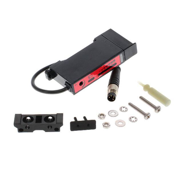
封装信息:黑色ABS外壳,丙烯酸盖板,光纤夹持元件为赛钢。
连接方式包括2米(6.5英尺)或9米(30英尺)PVC覆盖电缆,或带pico-style 4针QD连接器的6英寸电缆。