0
登录后你可以
  • 下载海量资料
  • 学习在线课程
  • 观看技术视频
  • 写文章/发帖/加入社区
会员中心
创作中心
发布
  • 发文章

  • 发资料

  • 发帖

  • 提问

  • 发视频

创作活动
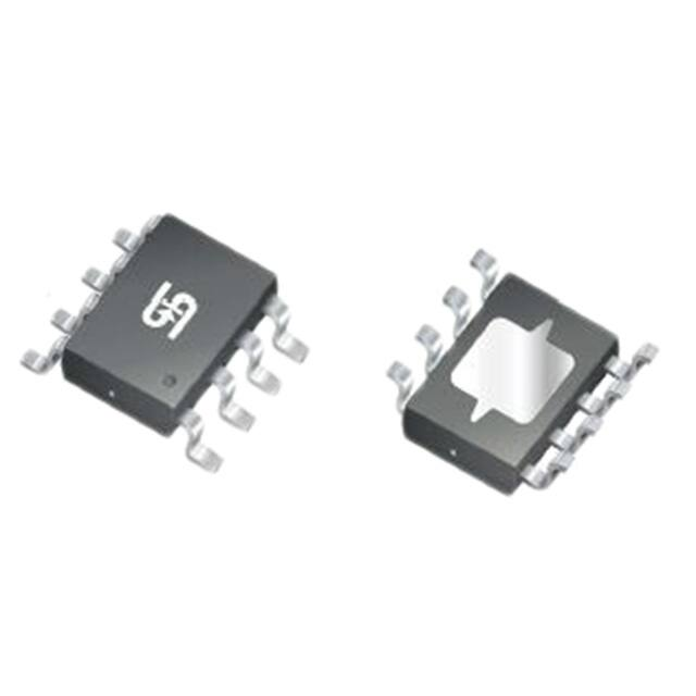
TS2581CS RLG

TS2581CS RLG

  • 厂商:

    TAIWANSEMICONDUCTOR(台半)

  • 封装:

    SOP8_150MIL

  • 描述:

    SWITCHING REGULATOR, DC-DC, BUCK

  • 详情介绍
  • 数据手册
  • 价格&库存
TS2581CS RLG 数据手册
TS2581 PWM Controller SOP-8 Pin Definition: 1. EN/CT 8. FB 2. GND 7. OVP 3. VGATE 6. VSENSE 4. VCC 5. GATE General Description The TS2581 integrates Pulse-Width-Modulation (PWM) control circuit into a single chip, mainly designs for powersupply regulator. All the functions include an error amplifier, a soft-start, UVLO, OVP, SCP, TSD circuitry. This device features an internal 100KHz oscillator, the UVLO makes sure that the outputs are off until the internal circuit operates normally. Features Ordering Information ● Input voltage:8V to 40V ● Duty ratio:0% to 100% PWM control ● Oscillation frequency:100K/300KHz ● Thermal Shutdown function. ● Short Circuit Protect (SCP). Application ● External SW P-channel MOS. ● Simple High-efficiency Step down Regulator ● External OVP setting function. ● ● Current mode non-synchronous PWM converter Charger ● ● External current limit setting. Telecommunication ● Under voltage Lockout. Part No. Package Packing TS2581CS RLG SOP-8 2.5kpcs / 13” Reel Note: “G” denotes for Halogen Free Absolute Maximum Rating Parameter VIN Pin Voltage Symbol Limit Unit VIN GND - 0.3 to GND + 45 V GND - 0.3 to VIN V VGATE,ISENSE Pin Voltage Feedback, OVP, EN/CT Pin Voltage GND - 0.3 to 6 V Switch Pin Voltage VSW GND - 0.3 to VIN + 0.3 V Power Dissipation PD (TJ – TA)/ θJA W Storage Temperature Range TST -40 to +165 °C Operating Temperature Range TOP -20 to +125 °C Operating Supply Voltage VOP +8.5 to +40 V Symbol Maximum 15 Thermal Information Parameter ӨJC Thermal Resistance (Junction to Case) Unit o C/W o Thermal Resistance (Junction to Ambient) ӨJA 40 C/W Note1: ӨJA is measured on the PCB with minimum copper area. 2 Note2: ӨJA is measured with the PCB copper area (need connect to GROUND pins) of approximately 0.5 in 1/7 Version: A11 TS2581 PWM Controller Electrical Specifications (Ta = 25oC unless otherwise noted, VIN=12V) Characteristics Symbol Conditions Feedback Voltage VFB IOUT=10mA Under Voltage Lockout UVLO Falling UVLO Hysteresis - OVP detect voltage VOVP Internal define Min. Typ. Max. Units 0.98 1 1.02 V - 6 - V - 0.8 - V 1.07 1.1 1.13 V Line Regulation REGLINE VIN=10 ~ 40V, IOUT=10mA - 0.5 1 % Load Regulation REGLOAD IOUT=0~3A, RSENSE = 33mΩ - 30 50 mV Quiescent Current ICCQ VFB = 1.5V, force driver off. - 3 6 mA Oscillator frequency FOSC IOUT = 0.5A 70 100 130 KHz Force driver on VFB = 0.6V - 100 - % Force driver off VFB = 1.5V - 0 - % - 110 - mV - - 0.4 V 0.5 - 1.5 V Max. Duty Cycle (ON) DC Min. Duty Cycle (OFF) Sense Voltage VCC-VSENSE EN/CT pin logic input threshold voltage VEN1 Shutdown mode VCT Auto restart, VFB1.10V, the OVP is happened that it can turn-off the driver. Under Voltage Lockout (UVLO) To avoid error-operation of the device at low input voltages an under voltage lockout is included that disables the device, if the input voltage falls below 6.0V Thermal Consderation The SOP-8L package needs a heat sink under most conditions. The heat sink connect exposed pad of TS2581 to obtain best effect. The size of the heat sink depends on the input voltage, output voltage, output current and ambient temperature. Typical Application Circuit VCC 10~36V ICL = RSENSE1 470uF 0.1u 1uF 8 7 6 5 L1 D1 4 3 2 1 VCC VGATE GATE VSENSE GND EN/CT OVP FB 5 R1 0R 66uH / 33uH R2 R3 C5 C4 Option 470uF R4 4 C3 D 3 2 1 S C2 P-MOS 33mR U2 C1 5V/3A U1 ( VCC - Vsense ) / Rsense 6 B340A 7 Option 8 C6 12K 12K R5 R6 3K 3K Option C7 0.1u AX3304/A TS2581 3/7 Version: A11 TS2581 PWM Controller Application Information Setting the Output Voltage Application circuit item shows the basic application circuit with adjustable output version. The external resistor sets the output voltage according to the following formula: VOUT = 1.0V × (1+ R3 ) R6 Table 1 Resistor select for output voltage setting VOUT R6 R3 5.0V 3.3V 3K 3K6 12K 8K2 Current Limit Protection The Current limit is set by outside resistance (RSENSE), When the SENSE pin voltage larger than 110mV, the current limit is happened that driver can be turned off until small than 90mV. The current limit set according to the following formula: Current Limit (A) = 110mV RSENSE The maximum output current table is shown as below; please refer the table to design. RSENSE (Ω) Current Limit (A) Maximum Output Current (A) 25m 30m 50m 75m 4.4 3.66 2.2 1.46 4.1 3.3 1.9 1.1 Inductor Selection For most designs, the different frequency can be reducing the inductor value; The TS2581 is suggested 22µH to 100µH for 100K to 300KHz frequencies. Please refer the below table to design. L1 recommend value (VIN=10~30V ,VOUT=5V, IOUT=2A) L1 Value (H) 68~100uF Where is inductor Ripple Current. Large value inductors lower ripple current and small value inductors result in high ripple currents. Choose inductor ripple current approximately 20% of the maximum load current 3A, ∆IL=0.6A. The DC current rating of the inductor should be at least equal to the maximum load current plus half the ripple current to prevent core saturation (3A+0.3A). Input Capacitor Selection This capacitor should be located close to the IC using short leads and the voltage rating should be approximately 1.5 times the maximum input voltage. The RMS current rating requirement for the input capacitor of a buck regulator is approximately 1⁄2 the DC load current. A low ESR input capacitor sized for maximum RMS current must be used. A 220~470µF low ESR capacitor for most applications is sufficient. 4/7 Version: A11 TS2581 PWM Controller Application Information (Continue) Output Capacitor Selection The output capacitor is required to filter the output and provide regulator loop stability. The important capacitor parameters are; the 100 KHz Equivalent Series Resistance (ESR), the RMS ripples current rating, voltage rating, and capacitance value. For the output capacitor, the ESR value is the most important parameter. The ESR can be calculated from the following formula. V RIPPLE = ∆ I L × ESR = 0.6A x 80mΩ= 48mV An aluminum electrolytic capacitor’s ESR value is related to the capacitance and its voltage rating. In most case, higher voltage electrolytic capacitors have lower ESR values. Most of the time, capacitors with much higher voltage ratings may be needed to provide the low ESR values required for low output ripple voltage. System stability is depending on output capacitor’s ESR, Correct to choose output capacitor’s ESR is very important. It is recommended to using a 220~470µF, the ESR values range is 40~130mΩ. EN/CT The pin is enable/shutdown and auto restart control functions. When system is normal operating, this pin is enable/shutdown function. Pulling this pin below a threshold voltage of under 0.3V shuts the regulator off, and pulling this pin from 0.5V to 1.5V turns the regulator on. However when VOUT is short (VFB
TS2581CS RLG
物料型号:TS2581 PWM 控制器

器件简介:TS2581是一款集成了脉宽调制(PWM)控制电路的单芯片,主要设计用于电源调节器。它包含了误差放大器、软启动、欠压锁定(UVLO)、过压保护(OVP)、短路保护(SCP)、热关断(TSD)电路。

引脚分配: - 1. EN/CT:使能/关断和自动重启控制引脚 - 2. GND:地引脚 - 3. VGATE:驱动门极钳位引脚,必须连接1μF电容至VIN - 4. VCC:操作电压输入 - 5. GATE:开关引脚,连接外部电感和二极管 - 6. VSENSE:电压感测输入 - 7. OVP:过电压检测引脚 - 8. FB:反馈引脚

参数特性: - 输入电压:8V 至 40V - PWM控制占空比:0% 至 100% - 振荡频率:100KHz/300KHz - 热关断功能 - 短路保护(SCP) - 外部SW P沟道MOS - 外部OVP设定功能 - 当前模式非同步PWM转换器 - 外部电流限制设定 - 欠压锁定

功能详解: - 反馈:感测调节输出电压以完成反馈回路。 - VSENSE:电流限制感测引脚,若VIN-VSENSE≥110mV,则发生过电流,可以逐周期关闭驱动。 - OVP:过电压感测引脚,若VOVP>1.10V,则发生OVP,可以关闭驱动。 - UVLO:避免在低输入电压下错误操作设备,包括欠压锁定功能。

应用信息: - 简单的高效率降压调节器 - 充电器 - 通信设备

封装信息:SOP-8封装,2.5kpcs/13英寸卷轴包装。注意:“G”表示无卤产品。

绝对最大额定值和热信息提供了器件在极端条件下的电压和温度限制,以及热阻参数。

电气规格详细列出了在不同条件下的最小值、典型值和最大值,包括反馈电压、欠压锁定电压、过电压检测电压、线路调节、负载调节、静态电流、振荡频率、最大占空比、最小占空比和感测电压等。

典型应用电路展示了一个5V/3A的降压调节器应用实例,包括外部元件的选择和连接方式。

应用信息进一步解释了如何设置输出电压、电流限制保护、电感选择、输入电容选择、输出电容选择和EN/CT引脚的功能。

热考虑强调了SOP-8L封装在大多数情况下需要散热器,并提供了散热器连接和尺寸选择的指导。

SOP-8机械绘图提供了封装的尺寸和标记图。
TS2581CS RLG 价格&库存

很抱歉,暂时无法提供与“TS2581CS RLG”相匹配的价格&库存,您可以联系我们找货

免费人工找货