Technical Data 11040
Effective March 2020
DRAP124
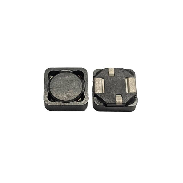
Automotive grade high power density, shielded drum core
power inductors
Applications
•
•
Product features
Body electronics
• LED lighting (interior and exterior)
•
Central body control module
•
Vehicle access control module
•
Headlamps, tail lamps and interior lighting
•
Heating ventilation and air conditioning
controllers (HVAC)
•
Doors, window lift and seat control
Advanced driver assistance systems
• Adaptive cruise control (ACC)
AEC-Q200 qualified
•
Automatic parking control
•
Secure four terminal mounting ideal for severe
vibration environments up to 30 g.
•
Collision avoidance system/ Car black
box system
•
Rugged construction for high shock conditions
•
Magnetically shielded-reduces EMI
•
Inductance range from 0.42 μH to 1001 μH
•
Digital instrument cluster
•
Current range from 0.38 A to 30.8 A
•
In-vehicle infotainment (IVI) and navigation
•
12.5 mm x 12.5 mm x 4.6 mm surface mount
package
•
•
•
Infotainment and cluster electronics
• Audio subsystem: head unit and trunk amp
Chassis and safety electronics
•
Electronic stability control system (ESC)
Electric parking brake
Electronic power steering (EPS) / Anti-locking
braking system (ABS)
•
Ferrite core material
•
•
Weight: 2.32 grams typical
•
•
Moisture Sensitivity Level: 1
•
Engine and powertrain systems
• Electric pumps, motor control and auxiliaries
•
Powertrain control module (PCU)/
Engine control unit (ECU)
•
Transmission control unit (TCU)
Environmental compliance and general
specifications
•
Storage temperature range (Component):
-40 °C to +165 °C
•
Operating temperature range: -40 °C to +165 °C
(ambient plus self-temperature rise)
•
Solder reflow temperature:
J-STD-020 (latest revision) compliant
HALOGEN
Pb HF
FREE
�DRAP124
Automotive grade high power density,
shielded drum core power inductors
Technical Data 11040
Effective March 2020
Product specifications
Part number6
OCL1 (µH)
±20%
Irms2
(A)
Isat13
(A)
Isat24
(A)
DCR (Ω)
typical @ +25 °C
DCR (Ω)
maximum @ +25 °C
K Factor5
DRAP124-R47-R
0.42
13.5
30.8
24.6
0.0024
0.0028
196.9
DRAP124-1R0-R
0.82
11.65
22.0
17.6
0.0031
0.0038
140.7
DRAP124-1R5-R
1.36
9.36
17.1
13.7
0.0049
0.0058
109.4
DRAP124-2R2-R
2.04
7.64
14.0
11.2
0.0070
0.0090
89.5
DRAP124-3R3-R
2.79
6.94
11.9
9.48
0.0090
0.011
75.7
DRAP124-4R7-R
4.74
5.47
9.06
7.25
0.014
0.017
57.9
DRAP124-6R8-R
7.28
4.46
7.33
5.87
0.021
0.026
46.9
DRAP124-8R2-R
8.88
3.87
6.70
5.36
0.028
0.034
42.8
DRAP124-100-R
10.4
3.67
6.16
4.93
0.031
0.038
39.4
DRAP124-150-R
14.1
3.10
5.31
4.25
0.044
0.053
34.0
DRAP124-220-R
23.0
2.44
4.16
3.33
0.071
0.086
26.6
DRAP124-330-R
34.1
1.98
3.42
2.74
0.108
0.130
21.9
DRAP124-470-R
46.3
1.78
2.91
2.33
0.134
0.160
18.6
DRAP124-680-R
69.8
1.45
2.37
1.90
0.201
0.241
15.1
DRAP124-820-R
80.6
1.29
2.23
1.79
0.257
0.309
14.3
DRAP124-101-R
98.8
1.20
2.00
1.60
0.296
0.355
12.8
DRAP124-151-R
152
0.967
1.62
1.30
0.454
0.550
10.4
DRAP124-221-R
209
0.865
1.36
1.09
0.568
0.680
8.7
DRAP124-331-R
326
0.690
1.09
0.874
0.892
1.070
7.0
DRAP124-471-R
473
0.568
0.911
0.729
1.32
1.58
5.8
DRAP124-681-R
682
0.466
0.759
0.607
1.96
2.35
4.9
DRAP124-821-R
826
0.406
0.697
0.557
2.57
3.09
4.5
DRAP124-102-R
1001
0.380
0.629
0.503
2.94
3.52
4.0
1. Open circuit inductance (OCL) test parameters: 100 kHz, 0.25 Vrms, 0.0 Adc, +25 °C
2. Irms: DC current for an approximate temperature rise of 40 °C without core loss. Derating is necessary
for AC currents. PCB layout, trace thickness and width, air-flow, and proximity of other heat generating components will affect the temperature rise. It is recommended that the temperature of the part
not exceed +165 °C under worst case operating conditions verified in the end application.
3. Isat1: Peak current for approximately 30% rolloff @ +25 °C
4. Isat2: Peak current for approximately 40% rolloff @ +125 °C
2
www.eaton.com/electronics
5. K-factor: Used to determine Bp-p for core loss (see graph). Bp-p = K * L * ΔI. Bp-p:(Gauss), K:
(K-factor from table), L: (Inductance in μH), ΔI (Peak-to-peak ripple current in Amps).
6. Part Number Definition: DRAP124-xxx-R
DRAP124= Product code and size
xxx= Inductance value in μH, R= decimal point, If no R is present last character equals number of
zeros
-R suffix = RoHS compliant
�DRAP124
Automotive grade high power density,
shielded drum core power inductors
Dimensions (mm)
Technical Data 11040
Effective March 2020
Recommended pad layout
Epoxy
2.00±0.10
0.20±0.10
DRAP124
xxx
xxxx R
Schematic
1
dummy
12.50 Max
5.40±0.10
#2
#1
CL
13.00±0.10
2
6.80±0.10
Epoxy
12.5 Max
dummy
0.20±0.10
CL
4.60 Max
6.80±0.10
13.00±0.10
Refer to the notes for epoxy/flashing
protrusion specification
Epoxy
1.60
2.50
5.00
Epoxy
#2
#1
12.00
7.00 Ref.
Pin1 Indicator
7.00 Ref.
2.50
12.00
Part marking: DRAP124, xxx= inductance value in uH, R= decimal point,
if no R is present last character equals number of zeros,
xxxx=lot code, R= Revision level
All soldering surface to be coplanar within 0.1 millimeters
Tolerances are ±0.2 millimeters unless stated otherwise
Special Characteristic epoxy protrusion or any flashing from the plastic on the header/base can be
below the terminal surface and must not exceed 0.08 mm beyond the bottom surface of the
terminal.
Terminal pads shall protrude the plastic base 0.00~0.08 mm
Traces or vias underneath the inductor is not recommended
Packaging information (mm)
Supplied in tape and reel packaging , 750 parts per 13” diameter reel
www.eaton.com/electronics
3
�DRAP124
Automotive grade high power density,
shielded drum core power inductors
Technical Data 11040
Effective March 2020
Temperature rise vs. total loss
70
Temperature rise (°C)
60
50
40
30
20
10
0
0
0.1
0.2
0.3
0.4
0.5
0.6
0.7
0.8
0.9
1.0
1.1
1.2
1.3
Total loss (W)
Core loss vs. Bp-p
1
10
Hz
M
0
kH
z
z
z
50
30
0
kH
20
0
kH
z
0
10
kH
Core loss (W)
1
0.1
0.01
0.001
100
1000
10000
Bp-p (Gauss)
Inductance characteristics
120%
110%
100%
% of OCL
90%
80%
-40 °C
70%
60%
+25 °C
50%
40%
+85 °C
30%
+125 °C
20%
10%
0%
0% 10% 20% 30% 40% 50% 60% 70% 80% 90% 100% 110% 120% 130% 140% 150%160%
% of Isat1
4
www.eaton.com/electronics
�DRAP124
Automotive grade high power density,
shielded drum core power inductors
Technical Data 11040
Effective March 2020
Solder reflow profile
TP
TC -5°C
tP
Max. Ramp Up Rate = 3°C/s
Max. Ramp Down Rate = 6°C/s
Temperature
TL
Preheat
A
T smax
t
Table 1 - Standard SnPb solder (Tc)
Package
thickness
Volume
mm3
很抱歉,暂时无法提供与“DRAP124-820-R”相匹配的价格&库存,您可以联系我们找货
免费人工找货