Technical Data 4119
Effective December 2015
Supersedes March 2007
FP4
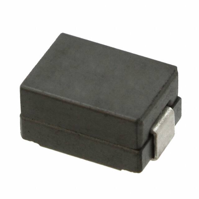
High current power inductors
Applications
Product description
•
High current carrying capacity
•
Inductance range from 0.090uH to 0.200uH
•
Current range 30 to 72 Amps
•
10.2 x 6.8mm footprint surface mount package
in a 5.0mm height
•
Ferrite core material
•
Halogen free, lead free, RoHS compliant
•
Servers
•
Multi-phase and Vcore regulators
•
Voltage Regulator Modules (VRMs)
• Server and desktop
•
Central processing unit (CPU)
•
Graphics processing unit (GPU)
•
Application specific integrated circuit (ASIC)
•
High power density
•
Battery power systems
•
Graphics cards
Environmental data
•
Storage temperature range (component):
-40°C to +155°C
•
Operating temperature range: -45°C to +155°C
(Ambient plus self temperature rise)
•
Solder reflow temperature: J-STD-020D
compliant
HALOGEN
Pb HF
FREE
�FP4
High current power inductors
Technical Data 4119
Effective December 2015
Product specifications
Part number5
OCL1 (μH)
±15%
lrms2 (amps)
lsat3 (amps)
DCR (Ω) typical
@ 20°C
DCR (Ω) maximum
@ 20°C
Volt-μsec4
(V-usec)
FP4-100-R
0.100
40
64
0.00038
0.00065
1.33
FP4-120-R
0.120
40
54
0.00038
0.00065
1.33
FP4-150-R
0.150
40
42
0.00038
0.00065
1.33
FP4-200-R
0.200
40
30
0.00038
0.00065
1.33
4. Applied Volt-Time product (V-μs) across the inductor. This value represents the applied V-μs at
500kHz necessary to generate a core loss equal to 10% of the total losses for 40°C temperature rise.
5. Part Number Definition: FP4-xxx-R
FP4 = Product code and size
xxx= Inductance value in uH, R= decimal point
-R suffix = RoHS compliant
1. Open Circuit Inductance (OCL) Test parameters: 1MHz, 0.100Vrms, 0.0Adc @20°C.
2. Irms: DC current for an approximate ΔT of 40°C without core loss. Derating is necessary for AC
currents. PCB layout, trace thickness and width, airflow, and proximity of other heat generating
components will affect the temperature rise. It is recommended that the temperature of the part
not exceed 155°C.
3. Isat : Peak current for approximately 30% rolloff @ +20ºC.
Part number5
OCL1 (μH)
±15%
lrms2 (amps)
lsat3 (amps)
DCR (mΩ) @25°C
Volt-μsec4 (V-usec)
FP4-090SK-R
0.090
33
72
0.423-0.517
1.33
4. Applied Volt-Time product (V-μs) across the inductor. This value represents the applied V-μs at
500kHz necessary to generate a core loss equal to 10% of the total losses for 40°C temperature rise.
5. Part Number Definition: FP4-xxxSK-R
FP4, SK = Product code and size
xxx= Inductance value in uH, R= decimal point
-R suffix = RoHS compliant
1. Open Circuit Inductance (OCL) Test parameters: 100kHz, 1.0Vrms, 0.0Adc @25°C.
2. Irms: DC current for an approximate ΔT of 40°C without core loss. Derating is necessary for
AC currents. PCB layout, trace thickness and width, airflow, and proximity of other heat generating
components will affect the temperature rise. It is recommended that the temperature of the part
not exceed 155°C.
3. Isat : Peak current for approximately 20% rolloff @ +25ºC.
Dimensions–mm
TOP VIEW
SIDE VIEW
FP4-XXX
or
FP4-XXXSK
wwllyy R
1
RECOMMENDED PAD LAYOUT
FRONT VIEW
1.0 min.
(2x)
10.20
Max
5.00 Max
1.30 ref.
(2x)
A
2
10.50
2.50 (2x)
Part Number
Dimension “A”
(mm) ref.
FP4-100-R
3 .0
FP4-120-R
3 .0
FP4-150-R
3 .0
FP4-200-R
3 .0
FP4-090SK-R
2 .8
SCHEMATIC
1
2
4.50 (2x)
6.80
Max
Part marking:
FP4-xxx (FP4=Product code and size),(xxx=inductance value in uH, R=decimal point)
FP4-xxxSK (FP4, SK=Product code and size),(xxx=inductance value in uH, R=decimal point)
wwllyy = date code, R = revision level
Tolerances are ±0.15 millimeters unless stated otherwise
PCB tolerances are ±0.2 millimeters unless stated otherwise
Do not route traces or vias underneath the inductor
Packaging information (mm)
Supplied in tape and reel packaging, 900 parts per 13” diameter reel.
12.0
2.00 ±0.1
0.35 ±0.05
Ø1.50 Min.
A
4.00
Ø1.50 +0.1/-0.0
1.75±0.10
R0.30 Max.
Ao=7.20mm
Bo=10.60mm
Ko=5.40mm
2
www.eaton.com/elx
Ko
SECTION A-A
11.50±0.1
FP4-XXX
or
FP4-XXXSK
wwllyy R
Bo
Ao
A
User direction of feed
R0.50 Typ.
24.00
±0.3
�FP4
High current power inductors
Technical Data 4119
Effective December 2015
Inductance characteristics
OCL vs. Isat
100.0
% of OCL
75.0
FP4-100
FP4-150
FP4-200
50.0
FP4-120
25.0
0.0
0
10
20
30
Isat (ADC)
40
50
OCL vs Isat
100
% of OCL
75
FP4-090SK
50
25
0
0
5
10
15
20
25
30
35
40
45
50
55
60
65
70
75
Isat (ADC)
www.eaton.com/elx
3
�FP4
High current power inductors
Technical Data 4119
Effective December 2015
Core loss
Irms Derating with Core Loss
0
20
40
50
70
Hz
z
0k
10
Hz
kH
300
500
k
1M
Hz
80
1.5
MH
z
% of Losses from Irms (maximum)
60
90
92
94
95
96
97
98
99
10
20
30
40
50
60
80
100
% of Applied Volt-μ-second
4
www.eaton.com/elx
200
300
400
500 600
800
1000
�FP4
High current power inductors
Technical Data 4119
Effective December 2015
Solder reflow profile
TP
TC -5°C
tP
Max. Ramp Up Rate = 3°C/s
Max. Ramp Down Rate = 6°C/s
Temperature
TL
Preheat
A
T smax
t
Table 1 - Standard SnPb Solder (Tc)
Package
Thickness
Volume
mm3
很抱歉,暂时无法提供与“FP4-090SK-R”相匹配的价格&库存,您可以联系我们找货
免费人工找货- 国内价格 香港价格
- 900+11.87401900+1.48903
