MMBT5401
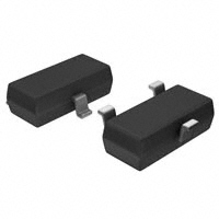
SOT-23 Plastic-Encapsulate Transistors
MMBT5401
TRANSISTOR (PNP)
SOT-23
FEATURES
z Complementary to MMBT5551
z Ideal for Medium Power Amplification and Switching
1. BASE
2. EMITTER
3. COLLECTOR
MARKING:2L
MAXIMUM RATINGS (Ta=25℃ unless otherwise noted)
Symbol
Parameter
Value
Unit
VCBO
Collector-Base Voltage
-160
V
VCEO
Collector-Emitter Voltage
-160
V
VEBO
Emitter-Base Voltage
-5
V
IC
Collector Current
-0.6
A
PC
Collector Power Dissipation
0.3
W
Thermal Resistance From Junction To Ambient
416
℃/W
Tj
Junction Temperature
150
℃
Tstg
Storage Temperature
-55~+150
℃
(3)C
2L
(1)B
RΘJA
(2)E
ELECTRICAL CHARACTERISTICS (Ta= 25℃ unless otherwise specified)
Parameter
Collector-base breakdown voltage
Symbol
V(BR)CBO
*
Collector-emitter breakdown voltage
V(BR)CEO
Emitter-base breakdown voltage
V(BR)EBO
Collector cut-off current
ICBO
Emitter cut-off current
IEBO
DC current gain
Collector-emitter saturation voltage
Base-emitter saturation voltage
Test
conditions
Min
Typ
Max
Unit
IC=-100µA, IE=0
-160
V
IC=-1mA, IB=0
-150
V
IE=-10µA, IC=0
-5
V
VCB=-120V, IE=0
-0.1
uA
VEB=-4V, IC=0
-0.1
uA
hFE(1)
*
VCE=-5V, IC=-1mA
80
hFE(2)
*
VCE=-5V, IC=-10mA
100
hFE(3)
*
VCE=-5V, IC=-50mA
50
300
VCE(sat)1
*
IC=-10mA, IB=-1mA
-0.2
V
VCE(sat)2
*
IC=-50mA, IB=-5mA
-0.5
V
VBE(sat)1
*
IC=-10mA, IB=-1mA
-1
V
VBE(sat)2
*
IC=-50mA, IB=-5mA
-1
V
VCE=-5V,IC=-10mA, f=30MHz
fT
Transition frequency
100
MHz
*Pulse test: pulse width ≤300μs, duty cycle≤ 2.0%.
CLASSIFICATION OF hFE
RANK
RANGE
http://www.microdiode.com
L
H
100–200
200–300
Rev:2024A1
Page :1
�MMBT5401
Typical Characteristics
Static Characteristic
-20
-100uA
VCE=-5V
COMMON
EMITTER
Ta=25℃
-90uA
o
hFE
-70uA
200
-12
-60uA
-10
-50uA
-8
-40uA
-6
Ta=100 C
250
-80uA
DC CURRENT GAIN
(mA)
-14
COLLECTOR CURRENT
-16
IC
-18
hFE —— IC
300
150
o
Ta=25 C
100
-30uA
-4
50
-20uA
-2
IB=-10uA
-0
-0
-3
0
-6
-9
COLLECTOR-EMITTER VOLTAGE
VCE
-1
VBEsat —— IC
-1.0
COLLECTOR-EMITTER SATURATION
VOLTAGE VCEsat (V)
BASE-EMITTER SATURATION
VOLTAGE VBEsat (V)
-0.6
Ta=100℃
-0.4
-0.2
-1
-10
COLLECTOR CURRENT
IC
IC
-0.1
Ta=25℃
-1
(mA)
-10
Cob / Cib
100
(mA)
IC
—— VCB / VEB
VCE=-5V
o
(pF)
o
Ta=100 C
Ta=25℃
-1
-0.2
-0.4
-0.6
-0.8
BASE-EMITTER VOLTAGE
fT
10
Cob
1
-0.5
-1.0
-1
-10
REVERSE VOLTAGE
VBE(V)
—— IC
Pc
0.4
COLLECTOR POWER DISSIPATION
Pc (W)
300
250
fT
(MHz)
Cib
C
-10
CAPACITANCE
COLLECTOR CURRENT
IC (mA)
f=1MHz
IE=0 / IC=0
Ta=25 C
-0.1
-0.0
TRANSITION FREQUENCY
-600
-100
COLLECTOR CURRENT
IC —— V
BE
-100
(mA)
Ta=100℃
-0.01
-0.1
-600
-100
IC
β=10
Ta=25℃
-0.0
-0.1
-600
-100
VCEsat ——
-1
β=10
-0.8
-10
COLLECTOR CURRENT
(V)
200
150
100
50
——
V
(V)
Ta
0.3
0.2
0.1
VCE=-5V
o
Ta=25 C
0
0.0
-0
-5
-10
-15
COLLECTOR CURRENT
http://www.microdiode.com
-20
IC
-25
(mA)
-30
0
25
50
75
AMBIENT TEMPERATURE
Rev:2024A1
100
Ta
125
150
(℃)
Page :2
�MMBT5401
Outlitne Drawing
SOT-23 Package Outline Dimensions
e
Suggested Pad Layout
0.037
0.95
0.037
0.95
L
L1
E
E1
Symbol
A
A1
b
c
D
E
E1
e
L
L1
θ
Dimensions In Millimeters
Min
Typ
Max
0.90
1.40
0.10
0.00
0.30
0.50
0.20
0.08
2.80
2.90
3.10
1.20
1.60
2.80
2.25
1.80
1.90
2.00
0.10
0.50
0.4
0°
0.55
10°
Note:
1. Controlling dimension:in/millimeters.
2. General tolerance: ±0.05mm.
3. The pad layout is for reference purposes only.
0.079
2.0
0.035
0.9
0.031
0.8
http://www.microdiode.com
inches
mm
Rev:2024A1
Page :3
�MMBT5401
SOT-23 Tape and Reel
Packaging Description:
SOT-23 parts are shipped in tape. The carrier
tape is made from a dissipative (carbon filled)
polycarbonate resin. The cover tape is a multilayer
film (Heat Activated Adhesive in nature) primarily
composed of polyester film,adhesive laye,sealant,
and anti-static sprayed agent.These reeled parts In
standard option are shipped with 3,000 units per 7"
or 17.8cm diameter reel. The reels are clear in color
and is made of polystyrene plastic (anti-static
coated).
3000 pcs
http://www.microdiode.com
7 Inch
45,000 pcs
203×203×195
180,000 pcs
438×438×220
Rev:2024A1
Page :4
�
很抱歉,暂时无法提供与“MMBT5401”相匹配的价格&库存,您可以联系我们找货
免费人工找货- 国内价格
- 1+0.21965
- 200+0.07303
- 1500+0.04566
- 3000+0.03623
- 国内价格
- 50+0.09418
- 500+0.07550
- 3000+0.06124
- 6000+0.05498
- 24000+0.04968
- 51000+0.04677
- 国内价格
- 50+0.07848
- 2400+0.05103
- 4800+0.04581