�Raspberry Pi Pico Datasheet
Colophon
Copyright © 2020 Raspberry Pi (Trading) Ltd.
The documentation of the RP2040 microcontroller is licensed under a Creative Commons Attribution-NoDerivatives 4.0
International (CC BY-ND).
build-date: 2021-01-21
build-version: fcd04ef-clean
Legal Disclaimer Notice
TECHNICAL AND RELIABILITY DATA FOR RASPBERRY PI PRODUCTS (INCLUDING DATASHEETS) AS MODIFIED FROM
TIME TO TIME (“RESOURCES”) ARE PROVIDED BY RASPBERRY PI (TRADING) LTD (“RPTL) "AS IS" AND ANY EXPRESS OR
IMPLIED WARRANTIES, INCLUDING, BUT NOT LIMITED TO, THE IMPLIED WARRANTIES OF MERCHANTABILITY AND
FITNESS FOR A PARTICULAR PURPOSE ARE DISCLAIMED. TO THE MAXIMUM EXTENT PERMITTED BY APPLICABLE
LAW IN NO EVENT SHALL RPTL BE LIABLE FOR ANY DIRECT, INDIRECT, INCIDENTAL, SPECIAL, EXEMPLARY, OR
CONSEQUENTIAL DAMAGES (INCLUDING, BUT NOT LIMITED TO, PROCUREMENT OF SUBSTITUTE GOODS OR
SERVICES; LOSS OF USE, DATA, OR PROFITS; OR BUSINESS INTERRUPTION) HOWEVER CAUSED AND ON ANY THEORY
OF LIABILITY, WHETHER IN CONTRACT, STRICT LIABILITY, OR TORT (INCLUDING NEGLIGENCE OR OTHERWISE)
ARISING IN ANY WAY OUT OF THE USE OF THE RESOURCES, EVEN IF ADVISED OF THE POSSIBILITY OF SUCH
DAMAGE.
RPTL reserves the right to make any enhancements, improvements, corrections or any other modifications to the
RESOURCES or any products described in them at any time and without further notice.
The RESOURCES are intended for skilled users with suitable levels of design knowledge. Users are solely responsible for
their selection and use of the RESOURCES and any application of the products described in them. User agrees to
indemnify and hold RPTL harmless against all liabilities, costs, damages or other losses arising out of their use of the
RESOURCES.
RPTL grants users permission to use the RESOURCES solely in conjunction with the Raspberry Pi products. All other use
of the RESOURCES is prohibited. No licence is granted to any other RPTL or other third party intellectual property right.
HIGH RISK ACTIVITIES. Raspberry Pi products are not designed, manufactured or intended for use in hazardous
environments requiring fail safe performance, such as in the operation of nuclear facilities, aircraft navigation or
communication systems, air traffic control, weapons systems or safety-critical applications (including life support
systems and other medical devices), in which the failure of the products could lead directly to death, personal injury or
severe physical or environmental damage (“High Risk Activities”). RPTL specifically disclaims any express or implied
warranty of fitness for High Risk Activities and accepts no liability for use or inclusions of Raspberry Pi products in High
Risk Activities.
Raspberry Pi products are provided subject to RPTL’s Standard Terms. RPTL’s provision of the RESOURCES does not
expand or otherwise modify RPTL’s Standard Terms including but not limited to the disclaimers and warranties expressed
in them.
Legal Disclaimer Notice
1
�Raspberry Pi Pico Datasheet
Table of Contents
Colophon . . . . . . . . . . . . . . . . . . . . . . . . . . . . . . . . . . . . . . . . . . . . . . . . . . . . . . . . . . . . . . . . . . . . . . . . . . . . . . . . . . . . . . . . . . . . . . . . . . . . 1
Legal Disclaimer Notice . . . . . . . . . . . . . . . . . . . . . . . . . . . . . . . . . . . . . . . . . . . . . . . . . . . . . . . . . . . . . . . . . . . . . . . . . . . . . . . . . . . . 1
1. About the Raspberry Pi Pico . . . . . . . . . . . . . . . . . . . . . . . . . . . . . . . . . . . . . . . . . . . . . . . . . . . . . . . . . . . . . . . . . . . . . . . . . . . . . . . . . 3
2. Mechanical Specification. . . . . . . . . . . . . . . . . . . . . . . . . . . . . . . . . . . . . . . . . . . . . . . . . . . . . . . . . . . . . . . . . . . . . . . . . . . . . . . . . . . . 6
2.1. Raspberry Pi Pico Pinout . . . . . . . . . . . . . . . . . . . . . . . . . . . . . . . . . . . . . . . . . . . . . . . . . . . . . . . . . . . . . . . . . . . . . . . . . . . . . . . 6
2.2. Surface Mount Footprint . . . . . . . . . . . . . . . . . . . . . . . . . . . . . . . . . . . . . . . . . . . . . . . . . . . . . . . . . . . . . . . . . . . . . . . . . . . . . . . 8
2.3. Recommended Operating Conditions . . . . . . . . . . . . . . . . . . . . . . . . . . . . . . . . . . . . . . . . . . . . . . . . . . . . . . . . . . . . . . . . . . . . 9
3. Electrical Specification. . . . . . . . . . . . . . . . . . . . . . . . . . . . . . . . . . . . . . . . . . . . . . . . . . . . . . . . . . . . . . . . . . . . . . . . . . . . . . . . . . . . . 11
3.1. Power Consumption . . . . . . . . . . . . . . . . . . . . . . . . . . . . . . . . . . . . . . . . . . . . . . . . . . . . . . . . . . . . . . . . . . . . . . . . . . . . . . . . . . 11
3.1.1. Popcorn . . . . . . . . . . . . . . . . . . . . . . . . . . . . . . . . . . . . . . . . . . . . . . . . . . . . . . . . . . . . . . . . . . . . . . . . . . . . . . . . . . . . . . . . 11
3.1.2. BOOTSEL mode . . . . . . . . . . . . . . . . . . . . . . . . . . . . . . . . . . . . . . . . . . . . . . . . . . . . . . . . . . . . . . . . . . . . . . . . . . . . . . . . . 13
3.1.3. DORMANT Mode . . . . . . . . . . . . . . . . . . . . . . . . . . . . . . . . . . . . . . . . . . . . . . . . . . . . . . . . . . . . . . . . . . . . . . . . . . . . . . . . 14
3.1.4. SLEEP Mode . . . . . . . . . . . . . . . . . . . . . . . . . . . . . . . . . . . . . . . . . . . . . . . . . . . . . . . . . . . . . . . . . . . . . . . . . . . . . . . . . . . . 15
4. Applications Information . . . . . . . . . . . . . . . . . . . . . . . . . . . . . . . . . . . . . . . . . . . . . . . . . . . . . . . . . . . . . . . . . . . . . . . . . . . . . . . . . . . 17
4.1. Programming the Flash . . . . . . . . . . . . . . . . . . . . . . . . . . . . . . . . . . . . . . . . . . . . . . . . . . . . . . . . . . . . . . . . . . . . . . . . . . . . . . . 17
4.2. General Purpose IO . . . . . . . . . . . . . . . . . . . . . . . . . . . . . . . . . . . . . . . . . . . . . . . . . . . . . . . . . . . . . . . . . . . . . . . . . . . . . . . . . . . 17
4.3. Using the ADC . . . . . . . . . . . . . . . . . . . . . . . . . . . . . . . . . . . . . . . . . . . . . . . . . . . . . . . . . . . . . . . . . . . . . . . . . . . . . . . . . . . . . . . 17
4.4. Powerchain. . . . . . . . . . . . . . . . . . . . . . . . . . . . . . . . . . . . . . . . . . . . . . . . . . . . . . . . . . . . . . . . . . . . . . . . . . . . . . . . . . . . . . . . . . 18
4.5. Powering Pico . . . . . . . . . . . . . . . . . . . . . . . . . . . . . . . . . . . . . . . . . . . . . . . . . . . . . . . . . . . . . . . . . . . . . . . . . . . . . . . . . . . . . . . 19
4.6. Using a Battery Charger . . . . . . . . . . . . . . . . . . . . . . . . . . . . . . . . . . . . . . . . . . . . . . . . . . . . . . . . . . . . . . . . . . . . . . . . . . . . . . . 20
4.7. USB. . . . . . . . . . . . . . . . . . . . . . . . . . . . . . . . . . . . . . . . . . . . . . . . . . . . . . . . . . . . . . . . . . . . . . . . . . . . . . . . . . . . . . . . . . . . . . . . . 21
4.8. Debugging. . . . . . . . . . . . . . . . . . . . . . . . . . . . . . . . . . . . . . . . . . . . . . . . . . . . . . . . . . . . . . . . . . . . . . . . . . . . . . . . . . . . . . . . . . . 21
Appendix A: Availability . . . . . . . . . . . . . . . . . . . . . . . . . . . . . . . . . . . . . . . . . . . . . . . . . . . . . . . . . . . . . . . . . . . . . . . . . . . . . . . . . . . . . . 22
Support . . . . . . . . . . . . . . . . . . . . . . . . . . . . . . . . . . . . . . . . . . . . . . . . . . . . . . . . . . . . . . . . . . . . . . . . . . . . . . . . . . . . . . . . . . . . . . . . . 22
Ordering code . . . . . . . . . . . . . . . . . . . . . . . . . . . . . . . . . . . . . . . . . . . . . . . . . . . . . . . . . . . . . . . . . . . . . . . . . . . . . . . . . . . . . . . . . . . 22
Appendix B: Pico Schematic . . . . . . . . . . . . . . . . . . . . . . . . . . . . . . . . . . . . . . . . . . . . . . . . . . . . . . . . . . . . . . . . . . . . . . . . . . . . . . . . . . 23
Appendix C: Pico Component Locations . . . . . . . . . . . . . . . . . . . . . . . . . . . . . . . . . . . . . . . . . . . . . . . . . . . . . . . . . . . . . . . . . . . . . . . 26
Table of Contents
2
�Raspberry Pi Pico Datasheet
Chapter 1. About the Raspberry Pi
Pico
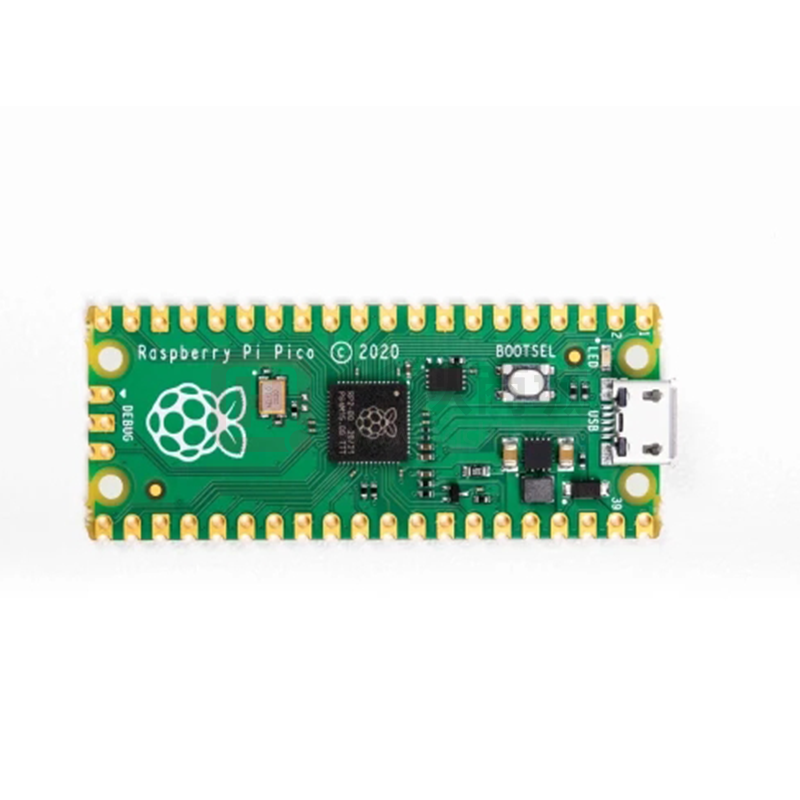
The Raspberry Pi Pico is a microcontroller board based on the Raspberry Pi RP2040 microcontroller chip.
Figure 1. The
Raspberry Pi Pico
Rev3 board.
Raspberry Pi Pico has been designed to be a low cost yet flexible development platform for RP2040, with the following
key features:
• RP2040 microcontroller with 2MByte Flash
• Micro-USB B port for power and data (and for reprogramming the Flash)
• 40 pin 21x51 'DIP' style 1mm thick PCB with 0.1" through-hole pins also with edge castellations
◦ Exposes 26 multi-function 3.3V General Purpose I/O (GPIO)
◦ 23 GPIO are digital-only and 3 are ADC capable
◦ Can be surface mounted as a module
• 3-pin ARM Serial Wire Debug (SWD) port
• Simple yet highly flexible power supply architecture
◦ Various options for easily powering the unit from micro-USB, external supplies or batteries
• High quality, low cost, high availability
• Comprehensive SDK, software examples and documentation
For full details of the RP2040 microcontroller please see the RP2040 Datasheet, however the headline features are:
• Dual-core cortex M0+ at up to 133MHz
◦ On-chip PLL allows variable core frequency
• 264kByte multi-bank high performance SRAM
Chapter 1. About the Raspberry Pi Pico
3
�Raspberry Pi Pico Datasheet
• External Quad-SPI Flash with eXecute In Place (XIP)
• High performance full-crossbar bus fabric
• On-board USB1.1 (device or host)
• 30 multi-function General Purpose IO (4 can be used for ADC)
◦ 1.8-3.3V IO Voltage (NOTE Pico IO voltage is fixed at 3.3V)
• 12-bit 500ksps Analogue to Digital Converter (ADC)
• Various digital peripherals
◦ 2 × UART, 2 × I2C, 2 × SPI, 16 × PWM channels
◦ 1 × Timer with 4 alarms, 1 × Real Time Counter
• 2 × Programmable IO (PIO) blocks, 8 state machines total
◦ Flexible, user-programmable high-speed IO
◦ Can emulate interfaces such as SD Card and VGA
Pico provides minimal (yet flexible) external circuitry to support the RP2040 chip (Flash, crystal, power supplies and
decoupling and USB connector). The majority of the RP2040 microcontroller pins are brought to the user IO pins on the
left and right edge of the board. Four RP2040 IO are used for internal functions - driving an LED, on-board Switched Mode
Power Supply (SMPS) power control and sensing the system voltages.
Pico has been designed to use either soldered 0.1" pin-headers (it is one 0.1" pitch wider than a standard 40-pin DIP
package) or can be used as a surface mountable 'module', as the user IO pins are also castellated. There are SMT pads
underneath the USB connector and BOOTSEL button, which allow these signals to be accessed if used as a reflowsoldered SMT module.
Figure 2. The pinout of
the Raspberry Pi Pico
Rev3 board.
Pico uses an on-board buck-boost SMPS which is able to generate the required 3.3 volts (to power RP2040 and external
circuitry) from a wide range of input voltages (~1.8 to 5.5V). This allows significant flexibility in powering the unit from
various sources such as a single Lithium-Ion cell, or 3 AA cells in series. Battery chargers can also be very easily
integrated with the Pico powerchain.
Reprogramming the Pico Flash can be done using USB (simply drag and drop a file onto the Pico which appears as a
Chapter 1. About the Raspberry Pi Pico
4
�Raspberry Pi Pico Datasheet
mass storage device) or via the Serial Wire Debug (SWD) port. The SWD port can also be used to interactively debug code
running on the RP2040.
The Pico schematic is reproduced in Appendix B document and the source design files, both the schematic and PCB, are
made available openly, with no limitations.
Permission to use, copy, modify, and/or distribute this design for any purpose with or without fee is hereby granted.
THE DESIGN IS PROVIDED "AS IS" AND THE AUTHOR DISCLAIMS ALL WARRANTIES WITH REGARD TO THIS DESIGN
INCLUDING ALL IMPLIED WARRANTIES OF MERCHANTABILITY AND FITNESS. IN NO EVENT SHALL THE AUTHOR BE
LIABLE FOR ANY SPECIAL, DIRECT, INDIRECT, OR CONSEQUENTIAL DAMAGES OR ANY DAMAGES WHATSOEVER
RESULTING FROM LOSS OF USE, DATA OR PROFITS, WHETHER IN AN ACTION OF CONTRACT, NEGLIGENCE OR OTHER
TORTIOUS ACTION, ARISING OUT OF OR IN CONNECTION WITH THE USE OR PERFORMANCE OF THIS DESIGN.
For further information on getting started with Pico please see the Getting started with Raspberry Pi Pico book.
Chapter 1. About the Raspberry Pi Pico
5
�Raspberry Pi Pico Datasheet
Chapter 2. Mechanical Specification
The Raspberry Pi Pico is a single sided 51x21mm 1mm thick PCB with a micro-USB port overhanging the top edge and
dual castellated/through-hole pins around the remaining edges. Pico is designed to be usable as a surface mount module
as well as being in Dual Inline Package (DIP) type format, with the 40 main user pins on a 2.54mm (0.1") pitch grid with
1mm holes and hence compatible with veroboard and breadboard. Pico also has 4x 2.1mm (+/- 0.05mm) drilled
mounting holes to provide for mechanical fixing, see Figure 3.
Figure 3. The
dimensions of the
Raspberry Pi Pico
Rev3 board.
2.1. Raspberry Pi Pico Pinout
The Pico pinout has been designed to directly bring out as much of the RP2040 GPIO and internal circuitry function as
possible, while also providing a suitable number of ground pins to reduce EMI (Electro Magnetic Interference) and signal
crosstalk. This is important in general but especially for RP2040 which is built on a modern 40nm silicon process and
hence the digital IO edge rates are very fast.
2.1. Raspberry Pi Pico Pinout
6
�Raspberry Pi Pico Datasheet
Figure 4. The pin
numbering of the
Raspberry Pi Pico
Rev3 board.
NOTE
The physical pin numbering is shown in Figure 4, for the pin allocation see Figure 2 or the full Raspberry Pi Pico
schematics in Appendix B.
A few RP2040 GPIO pins are used for internal board functions, these are:
GPIO29
IP Used in ADC mode (ADC3) to measure VSYS/3
GPIO25
OP Connected to user LED
GPIO24
IP VBUS sense - high if VBUS is present, else low
GPIO23
OP Controls the on-board SMPS Power Save pin (Section 4.4)
Apart from GPIO and ground pins, there are 7 other pins on the main 40-pin interface:
PIN40
VBUS
PIN39
VSYS
PIN37
3V3_EN
PIN36
3V3
PIN35
ADC_VREF
PIN33
AGND
PIN30
RUN
VBUS is the micro-USB input voltage, connected to micro-USB port pin 1. This is nominally 5V (or 0V if the USB is not
connected or not powered).
VSYS is the main system input voltage, which can vary in the allowed range 1.8V to 5.5V, and is used by the on-board
2.1. Raspberry Pi Pico Pinout
7
�Raspberry Pi Pico Datasheet
SMPS to generate the 3.3V for the RP2040 and its GPIO.
3V3_EN connects to the on-board SMPS enable pin, and is pulled high (to VSYS) via a 100K resistor. To disable the 3.3V
(which also de-powers the RP2040), short this pin low.
3V3 is the main 3.3V supply to RP2040 and its I/O, generated by the on-board SMPS. This pin can be used to power
external circuitry (maximum output current will depend on RP2040 load and VSYS voltage, it is recommended to keep the
load on this pin less than 300mA).
ADC_VREF is the ADC power supply (and reference) voltage, and is generated on Pico by filtering the 3.3V supply. This pin
can be used with an external reference if better ADC performance is required.
AGND is the ground reference for GPIO26-29, there is a separate analog ground plane running under these signals and
terminating at this pin. If the ADC is not used or ADC performance is not critical, this pin can be connected to digital
ground.
RUN is the RP2040 enable pin, and has an internal (on-chip) pull-up resistor to 3.3V of about ~50K Ohms. To reset
RP2040, short this pin low.
Finally, there are also 6 Test Points (TP1-TP6) which can be accessed if required, for example if using as a surface mount
module. These are:
TP1
Ground (close coupled ground for differential USB signals)
TP2
USB DM
TP3
USB DP
TP4
GPIO23/SMPS PS pin (do not use)
TP5
GPIO25/LED (not recommended to be used)
TP6
BOOTSEL
TP1, TP2 and TP3 can be used to access the USB signals instead of using the micro-USB port. TP6 can be used to drive
the system into mass-storage USB programming mode (by shorting it low at power-up). Note that TP4 is not intended to
be used externally, and TP5 is not really recommended to be used as it will only swing from 0V to the LED forward voltage
(and hence can only really be used as an output with special care).
2.2. Surface Mount Footprint
The following footprint (Figure 5) is recommended for systems which will be reflow-soldering Pico units as modules.
2.2. Surface Mount Footprint
8
�Raspberry Pi Pico Datasheet
Figure 5. The SMT
footprint of the
Raspberry Pi Pico
Rev3 board.
The footprint shows the test point locations and pad sizes as well as the 4 USB connector shell ground pads (A,B,C,D).
The USB connector on Pico is a through-hole part, which provides it with mechanical strength. The USB socket pins do not
protrude all the way through the board, however solder does pool at these pads during manufacture and can stop the
module sitting completely flat. Hence we provide pads on the SMT module footprint to allow this solder to reflow in a
controlled manner when Pico goes through reflow again.
For test points that are not used, it is acceptable to void any copper under these (with suitable clearance) on the carrier
board.
2.3. Recommended Operating Conditions
Operating conditions for the Raspberry Pi Pico are largely a function of the operating conditions specified by its
components.
Operating Temp Max
85C (including self-heating)
Operating Temp Min
-20C
VBUS
5V +/- 10%.
VSYS Min
1.8V
VSYS Max
5.5V
2.3. Recommended Operating Conditions
9
�Raspberry Pi Pico Datasheet
Note that VBUS and VSYS current will depend on use-case, some examples are given in the next section.
Recommended maximum ambient temperature of operation is 70C.
2.3. Recommended Operating Conditions
10
�Raspberry Pi Pico Datasheet
Chapter 3. Electrical Specification
3.1. Power Consumption
The power consumption shows the VBUS current consumption on three typical Raspberry Pi Pico devices, with four
different software use-cases. These results are not guaranteed maximum values, they are an indication of the current
consumption a user can typically expect the device to draw when used in these scenarios.
For more detailed current consumption data, please see the RP2040 Datasheet.
3.1.1. Popcorn
Firstly, 'Popcorn' (Media player demo) using the VGA, SD Card, and Audio board. This demo uses VGA video, I2S aduio and
4-bit SD Card access. This has been performed with (Table 1) and without (Table 2) the power saving (PS) mode of Pico’s
voltage regulator, controlled by GPIO23. The 'Average' data shows the mean current consumption over several seconds of
video, with varying colour and intensity. The 'Maximum' data is obtained during periods of white video, when the current
required is at its highest.
Table 1. Popcorn
running on the VGA
Pico Board
Board (VGA video, SD
Card and I2S audio)
Average VBUS Current @ 5V (mA)
Maximum VBUS Current @5V (mA)
Temperature (°C)
Temperature (°C)
-25
25
85
-25
25
85
#1
84.8
83.4
87.3
90.9
87.8
93.1
#2
87.5
89.9
89.8
93.4
94.1
94.0
#3
84.4
86.2
86.9
90.6
92.9
91.3
Mean
85.6
86.5
88.0
91.6
91.6
92.8
NOTE
Includes current consumed by VGA board (e.g. I2S DAC) in addition to the Raspberry Pi Pico. For more information on
the VGA board see the Hardware design with RP2040 book.
3.1. Power Consumption
11
�Raspberry Pi Pico Datasheet
Figure 6. Popcorn
running on the VGA
Board (Average
Current)
Figure 7. Popcorn
running on the VGA
Board (Maximum
Current)
Table 2. Popcorn
running on the VGA
Pico Board
Board (VGA video, SD
Card and I2S audio)
with power saving
Maximum VBUS Current @5V (mA)
Temperature (°C)
Temperature (°C)
-25
25
85
-25
25
85
#1
90.3
89.3
90.7
94.6
94.5
95.6
#2
91.2
87.1
90.6
95.4
91.0
95.5
#3
90.8
90.2
91.6
95.0
95.1
95.3
Mean
90.8
88.9
91.0
95.0
93.5
95.5
disabled (GPIO23
pulled high)
Average VBUS Current @ 5V (mA)
3.1. Power Consumption
12
�Raspberry Pi Pico Datasheet
Figure 8. Popcorn
running on the VGA
Board (Average
Current) with power
saving disabled
(GPIO23 pulled high)
Figure 9. Popcorn
running on the VGA
Board (Maximum
Current) with power
saving disabled
(GPIO23 pulled high)
3.1.2. BOOTSEL mode
Secondly, the BOOTSEL mode of RP2040, see Table 3. These measurements are made both with and without USB activity
on the bus, using a Raspberry Pi 4 as a host.
Table 3. BOOTSEL
mode
Pico Board
USB Idle VBUS Current @ 5V (mA)
USB Active VBUS Current @5V (mA)
Temperature (°C)
Temperature (°C)
-25
25
85
-25
25
85
#1
9.05
8.50
8.87
10.19
9.66
10.00
#2
9.58
9.12
9.20
10.64
10.35
10.36
#3
9.45
8.63
8.99
10.75
9.81
10.08
3.1. Power Consumption
13
�Raspberry Pi Pico Datasheet
Mean
9.4
8.7
9.0
10.5
9.9
10.1
Figure 10. BOOTSEL
mode, idle current.
Figure 11. BOOTSEL
mode, active current.
3.1.3. DORMANT Mode
The third use-case uses the hello_dormant binary which puts RP2040 into a low power state, DORMANT mode, see Table 4.
Table 4. Raspberry Pi
Pico running the
Pico Board
hello_dormant
VBUS Current @ 5V (mA)
Temperature (°C)
binary. Board is in
DORMANT mode
-25
25
85
#1
1.16
0.78
1.34
#2
1.19
0.92
1.40
3.1. Power Consumption
14
�Raspberry Pi Pico Datasheet
#3
1.29
0.85
1.33
Mean
1.2
0.8
1.4
Figure 12. Raspberry
Pi Pico running the
hello_dormant
binary. Board is in
DORMANT mode.
3.1.4. SLEEP Mode
The final use-case uses the hello_sleep binary code which puts RP2040 into a low power state, SLEEP mode, see Table 5.
Table 5. Raspberry Pi
Pico running the
Pico Board
hello_sleep
VBUS Current @ 5V (mA)
Temperature (°C)
binary. Board is in
SLEEP mode.
-25
25
85
#1
1.35
1.30
1.81
#2
1.53
1.39
1.92
#3
1.40
1.32
1.92
Mean
1.4
1.3
1.9
3.1. Power Consumption
15
�Raspberry Pi Pico Datasheet
Figure 13. Raspberry
Pi Pico running the
hello_sleep
binary. Board is in
SLEEP mode.
3.1. Power Consumption
16
�Raspberry Pi Pico Datasheet
Chapter 4. Applications Information
4.1. Programming the Flash
The on-board 2MByte QSPI Flash can be (re)programmed either using the Serial Wire Debug port or by the special USB
Mass Storage Device mode.
The simplest way to reprogram the Pico’s Flash is to use the USB mode. To do this, depower the board, then hold the
BOOTSEL button down during board power-up (e.g. hold BOOTSEL down while connecting the USB). The Pico will then
appear as a USB Mass Storage Device. Dragging a special '.uf2' file onto the disk will write this file to the Flash and restart
the Pico.
The USB boot code is stored in ROM on RP2040, so can not be accidentally overwritten.
To get started using the SWD port see the Debugging with SWD section in the Getting started with Raspberry Pi Pico
book.
4.2. General Purpose IO
The Raspberry Pi Pico’s GPIO is powered from the on-board 3.3V rail and is therefore fixed at 3.3V.
The Pico exposes 26 of the 30 possible RP2040 GPIO pins by routing them straight out to Pico header pins. GPIO0 to
GPIO22 are digital only and GPIO 26-28 are able to be used either as digital GPIO or as ADC inputs (software selectable).
One thing to note is that the ADC capable GPIO26-29 have an internal reverse diode to the VDDIO (3V3) rail and so the
input voltage must not exceed VDDIO plus about 300mV. Also, if the RP2040 is unpowered, applying a voltage to these
GPIO pins will 'leak' through the diode into the VDDIO rail. Normal digital GPIO pins 0-25 (and also the debug pins) do not
have this restriction and therefore voltage can safely be applied to these pins when RP2040 is upowered.
4.3. Using the ADC
The RP2040 ADC does not have an on-board reference and therefore uses its own power supply as a reference. On Pico
the ADC_AVDD pin (the ADC supply) is generated from the SMPS 3.3V by using an R-C filter (201 ohms into 2.2μF). This is
a simple solution but does have the following drawbacks:
1. We are relying on the 3.3V SMPS output accuracy which isn’t great
2. We can only do so much filtering and therefore ADC_AVDD will be somewhat noisy
3. The ADC draws current (about 150μA if the temperature sense diode is disabled, but it varies from chip to chip) and
therefore there will be an inherent offset of about 150μA*200 = ~30mV. There is a small difference in current draw
when the ADC is sampling (about +20μA) so that offset will also vary with sampling as well as operating
temperature.
Changing the resistance between the ADC_VREF and 3V3 pin can reduce the offset at the expense of more noise - which
may be OK especially if the use case can support averaging over multiple samples.
Driving high the SMPS mode pin (GPIO23), to force the power supply into PWM mode, can greatly reduce the inherent
ripple of the SMPS at light load, and therefore the ripple on the ADC supply. This does reduce the power efficiency of the
board at light load, so the low-power PFM mode can be re-enabled between infrequent ADC measurements by driving
GPIO23 low once more. See Section 4.4.
The ADC offset can be reduced by tying a second channel of the ADC to ground, and using this zero-measurement as an
approximation to the offset.
4.1. Programming the Flash
17
�Raspberry Pi Pico Datasheet
For much improved ADC performance, an external 3.0V shunt reference, such as LM4040, can be connected from the
ADC_VREF pin to ground. Note that if doing this the ADC range is limited to 0-3.0V signals (rather than 0-3.3V), and the
shunt reference will draw continuous current through the 200R filter resistor (3.3V-3.0V)/200 = ~1.5mA.
Note that the 1R resistor on Pico (R9) is designed to (maybe) help with shunt references that would otherwise become
unstable when directly connected to 2.2μF. It also makes sure there is a little filtering even in the case that 3.3V and
ADC_VREF are shorted together (which is a valid thing to do if you don’t care about noise and want to reduce the inherent
offset).
Finally, R7 is a physically large 1608 metric (0603) package resistor, so can be relatively easily removed if a user wants to
isolate ADC_VREF and do their own thing with the ADC voltage, for example powering it from an entirely separate voltage
(e.g. 2.5V). Note that the ADC on RP2040 has only been qualified at 3.0/3.3V but should work down to about 2V.
4.4. Powerchain
Raspberry Pi Pico has been designed with a simple yet flexible power supply architecture and can easily be powered from
other sources such as batteries or external supplies. Integrating the Pico with external charging circuits is also
straightforward. Figure 14 shows the power supply circuitry.
Figure 14. The
powerchain of the
Raspberry Pi Pico
Rev3 board.
VBUS is the 5V input from the micro-USB port, which is fed through a Schottky diode to generate VSYS. The VBUS to
VSYS diode (D1) adds flexibility by allowing power ORing of different supplies into VSYS.
VSYS is the main system 'input voltage' and feeds the RT6150 buck-boost SMPS, which generates a fixed 3.3V output for
the RP2040 device and its IO (and can be used to power external circuitry). VSYS is R-C filtered and divided by 3 (by R5, R6
and C3 in the Pico schematic) and can be monitored on ADC channel 3. This can be used for example as a crude battery
voltage monitor.
The buck-boost SMPS, as its name implies, can seamlessly switch from buck to boost mode, and therefore can maintain
an output voltage of 3.3V from a wide range of input voltages, ~1.8V to 5.5V, which allows a lot of flexibility in the choice
of power source.
GPIO24 monitors the existence of VBUS, while R10 and R1 act to pull VBUS down to make sure it is 0V if VBUS is not
present.
GPIO23 controls the RT6150 PS (Power Save) pin. When PS is low (the default on Pico) the regulator is in Pulse
Frequency Modulation mode, which, at light loads, saves considerable power by only turning on the switching MOSFETs
occasionally to keep the output capacitor topped up. Setting PS high forces the regulator into Pulse Width Modulation
(PWM) mode. PWM mode forces the SMPS to switch continuously, which reduces the output ripple considerably at light
loads (which can be good for some use cases) but at the expense of much worse efficiency. Note that under heavy load
the switcher will be in PWM mode irrespective of the PS pin state.
The SMPS EN pin is pulled up to VSYS by a 100K resistor and made available on Pico pin 37. Shorting this pin to ground
will disable the switcher and put it into a low power state.
4.4. Powerchain
18
�Raspberry Pi Pico Datasheet
NOTE
The RP2040 has an on-chip linear regulator (LDO) that powers the digital core at 1.1V (nominal) from the 3.3V supply,
which is not shown in Figure 14.
4.5. Powering Pico
The simplest way to power Pico is to plug in the micro-USB, which will power VSYS (and therefore the system) from the
5V USB VBUS voltage, via D1 (so VSYS becomes VBUS minus the Schottky diode drop).
If the USB port is the only power source, VSYS and VBUS can be safely shorted together to eliminate the Schottky diode
drop (which improves efficiency and reduces ripple on VSYS).
If the USB port is not going to be used, it is safe to power Pico by connecting VSYS to your preferred power source (in the
range ~1.8V to 5.5V).
IMPORTANT
If you are using Raspberry Pi Pico in USB Host mode (see for instance the USB HID example, https://github.com/
raspberrypi/pico-examples/tree/master/usb/host/host_hid/host_hid.c) then you must power Pico by providing 5V to
the VBUS pin.
The simplest way to safely add a second power source to Pico is to feed it into VSYS via another Schottky diode (See
Figure Figure 15). This will 'OR' the two voltages, allowing the higher of either the external voltage or VBUS to power VSYS,
with the diodes preventing either supply from back-powering the other. For example a single Lithium-Ion cell* (cell voltage
~3.0V to 4.2V) will work well, as will 3xAA series cells (~3.0V to ~4.8V) and any other fixed supply in the range ~2.3V to
5.5V. The downside of this approach is that the second power supply will suffer a diode drop in the same way as VBUS
does, and this may not be desirable from an efficiency perspective or if the source is already close to the lower range of
input voltage allowed for the RT6150.
Figure 15. Raspberry
Pi Pico power ORing
using diodes.
An improved way to power from a second source is using a P-channel MOSFET (P-FET) to replace the Schottky diode as
shown in Figure 16. Here, the gate of the FET is controlled by VBUS, and will disconnect the secondary source when VBUS
is present. The P-FET should be chosen to have low on resistance, and therefore overcomes the efficiency and voltagedrop issues with the diode-only solution.
Note that the Vt (threshold voltage) of the P-FET must be chosen to be well below the minimum external input voltage, to
4.5. Powering Pico
19
�Raspberry Pi Pico Datasheet
make sure the P-FET is turned on swiftly and with low resistance. When the input VBUS is removed, the P-FET will not
start to turn on until VBUS drops below the P-FETs Vt, meanwhile the body diode of the P-FET may start to conduct
(depending on whether Vt is smaller than the diode drop). For inputs that have a low minimum input voltage, or if the PFET gate is expected to change slowly (e.g. if any capacitance is added to VBUS) a secondary schottky diode across the
P-FET (in the same direction as the body diode) is recommended. This will reduce the voltage drop across the P-FETs
body diode.
An example of a suitable P-MOSFET for most situations is Diodes DMG2305UX which has a maximum Vt of 0.9V and Ron
of 100 milliohms (at 2.5V Vgs).
Figure 16. Raspberry
Pi Pico power ORing
using P channel
MOSFET.
CAUTION
If using Lithium-Ion cells they must have, or be provided with, adequate protection against over-discharge, over-charge,
charging outside allowed temperature range, and overcurrent. Bare, unprotected cells are dangerous and can catch
fire or explode if over-discharged, over-charged or charged / discharged outside their allowed temperature and/or
current range.
4.6. Using a Battery Charger
Pico can also be used with a battery charger. Although this is a slightly more complex use case it is still straightforward.
Figure 17 shows an example of using a 'Power Path' type charger (where the charger seamlessly manages swapping
between powering from battery or powering from the input source and charging the battery, as needed).
4.6. Using a Battery Charger
20
�Raspberry Pi Pico Datasheet
Figure 17. Using
Raspberry Pi Pico with
a charger.
In the example we feed VBUS to the input of the charger, and we feed VSYS with the output via the previously mentioned
P-FET arrangement. Depending on your use case you may also want to add a schottky diode across the P-FET as
described in the previous section.
4.7. USB
RP2040 has an integrated USB1.1 PHY and controller which can be used in both Device and Host mode. Pico adds the
two required 27 ohm external resistors and brings this interface to a standard micro-USB port.
The USB port can be used to access the USB bootloader (BOOTSEL mode) stored in the RP2040 boot ROM. It can also be
used by user code, to access an external USB device or host.
4.8. Debugging
Raspberry Pi Pico brings the RP2040 Serial Wire Debug (SWD) interface to a 3 pin debug header on the lower edge of the
board. To get started using the debug port see the Debugging with SWD section in the Getting started with Raspberry Pi
Pico book.
NOTE
The RP2040 chip has internal pull up resistors on the SWDIO and SWCLK pins, both nominally 60 kOhm.
4.7. USB
21
�Raspberry Pi Pico Datasheet
Appendix A: Availability
Raspberry Pi guarantee availability of the Raspberry Pi Pico product until at least January 2028.
Support
For support see the Pico section of the Raspberry Pi website, and post questions on the Raspberry Pi forum.
Ordering code
Table 6. Part Number
Model
Order Code
EAN
Minimal Order
RRP
Quantity
Raspberry Pi Pico
SC0915
0617588405587
1+ pcs / Bulk
US$4.00
NOTE
RRP was correct at time of publication and excludes taxes.
Support
22
�Raspberry Pi Pico Datasheet
Appendix B: Pico Schematic
See Figure 18 on the following page.
Appendix B: Pico Schematic
23
�Appendix B: Pico Schematic
Raspberry Pi Pico Datasheet
Figure 18. The
Raspberry Pi Pico
Rev3 board schematic.
24
�Raspberry Pi Pico Datasheet
Appendix B: Pico Schematic
25
�Raspberry Pi Pico Datasheet
Appendix C: Pico Component
Locations
Figure 19. The
Raspberry Pi Pico
Rev3 board
component locations.
Appendix C: Pico Component Locations
26
��