1mm Pitch Double Rows Low Profile Wire-to-Board Connectors
DF20 Series
Cable
5.4
Socket
DF20A**DS-1C
DF20EF(G)*DP-1V(52)
Cable
PCB
6.2
DF20F
**DP-1H(52)
Pin
Header
5.5
DF20A**DS-1C
Socket
PCB
■Features
1. Contact Pitch
Narrower external width and length
1mm contact pitch allows reliable solder and cable
termination.
2. Reliable electrical connection wipe
Effective electrical connection is assured with a 1mm
wipe of mating contacts.
3. Narrower external width and length
Redesigned metal fittings decreased the overall length
of the board- mount receptacle and permit end-to-end
mounting of several connectors.
4. Automatic equipment board placement
Straight type pin headers are supplied with a 5.4mm ×
4.6mm flat platform to allow vacuum pick-up and
placement on the board.
5. Product variations
Metal fitting
(1) Available with 10, 20, 30, 40, and 50 contacts.
(2) Pin headers are available in two types : with or
without board positioning bosses.
(3) Depending on specific application pin headers can
be ordered in straight or right angle types.
■Applications
Notebook PC, small office automation equipment, small
consumer devices, portable devices.
Any application requiring low profile reliable board-to-cable
connection with a 28 AWG, 30 AWG, 32 AWG conductors.
DF20F-****SCFA
Contact
DF20A-**DS-1C
Socket
DF20EF(G)*DP-1V(52)
Pin Header
1mm Pitch, Double Rows
1
Nov.1.2021 Copyright 2021 HIROSE ELECTRIC CO., LTD. All Rights Reserved.
5.8
Pin
Header
In cases where the application will demand a high level of reliability, such as automotive,
please contact a company representative for further information.
2021.2⑤
1
�DF20 Series●1mm Pitch Double Rows Low Profile Wire-to-Board Connectors
■Product Specifications
Rating
Operating temperature -35°C to +85°C
28 AWG : 1A/pin
(Note 1)
Rated current 30 AWG : 0.9A/pin range
32 AWG : 0.7A/pin
Operating humidity
-40% to 80%
range
(Note 2)
Rated voltage 100V AC/DC
Item
1. Insulation resistance
2. Withstanding voltage
3. Contact resistance
Specifications
500Mø min.
No flashover or insulation breakdown
30Mø max.
4. Vibration
No electrical discontinuity of 1µs min.
Contact resistance of 30mø max.,
insulation resistance of 100Mø min.
Contact resistance of 30mø max,
insulation resistance of 500Mø min.
Contact resistance of 30mø max.
No deformation of the insulator parts
that will affect performance
5. Humidity
Nov.1.2021 Copyright 2021 HIROSE ELECTRIC CO., LTD. All Rights Reserved.
6. Temperature cycle
7. Mechanical operation
8. Resistance to
Soldering heat
Storage temperature
range
-10°C to +60°C
Storage humidity
range
40% to 70%
Conditions
Measured at 100V DC
Conduction of 300V AC applied for 1 minute
Measure at 1mA.
Frequency of 10 to 55 Hz, single amplitude of 0.75mm,
in 3 directions for 10 cycles
Temperature of 40±2ç, humidity of 90% to 95%,
left standing for 96 hours
(-55ç : 30min / 5ç to 35ç : 2 to 3min / 85ç : 30min / 5ç
to 35ç : 2 to 3min ) for 5 cycles
50 cycles
Reflow : At the recommended temperature profile, manual
solder : Soldering iron temperature of 300ç for 3 seconds
Note1 : Includes temperature rise caused by current flow.
Note2 : No condensing.
Note3 : Information contained in this catalog represents general requirements for this Series. Contact us for the drawings and
specifications for a specific part number shown.
■Materials / Finish
Item
Socket
Crimping contact
Part
Insulator
Contact
Insulator
Contact
Metal Fitting
Pin header
Material
Polyamide
Phosphor bronze
Polyamide
Phosphor bronze
Brass
Finish
Color : Beige
Gold plating
Color : Beige
Gold plating
Tin Plating
Remarks
UL94V-0
---------UL94V-0
-------------------
Product Number Structure
Refer to the chart below when determining the product specifications from the product number.
Please select from the product numbers listed in this catalog when placing orders.
●Pin header
DF20 # - * DP - 1 V
❶
❷
❸
❶Series name
❷Boss Type
❹
❺
❻
:DF20, DF20E
❹Connector type
■F : Without boss
■G : With boss
❸Number of contacts
❺Contact pitch
❻Type of housing,
header
:10, 20, 30, 40, 50
DP:Double-row pin header
:1mm
V:Straight SMT header
H:Right angle SMT header
●Crimping contact
DF20 F - 2830 SCF A - (**)
❶
❷
❸
❶Applicable wire
size
2830:28 to 30 AWG
3032:30 to 32 AWG
❷Contact &
packaging type
SCF:Socket contact reel
❹
❸Plating type
❹Packaging
Specifications
A:Gold plating
04:1 reel = 10,000 pieces
44:1 reel = 20,000 pieces
●Crimp socket
DF20 A - * DS - 1 C
❶
❶Series name
❷Number of contacts
❸Connector type
2
❷
❸
❹
❺
:DF20A
❹Contact pitch
:10, 20, 30, 40, 50
❺Type of housing,
header
DS:Double-row socket
:1mm
C:Crimp housing
RoHS2
YES
�DF20 Series●1mm Pitch Double Rows Low Profile Wire-to-Board Connectors
Double Row Socket
A
B
P=1
Contact No.2
Contact No.1
Contact No.*
Contact No.*
5
4.28
4.1
5th contact marking
Contact No.1 mark
Unit : mm
Part No.
HRS No.
No. of Contacts
A
B
DF20A-10DS-1C
686-0020-3
10
17.2
14.0
DF20A-20DS-1C
686-0021-6
20
12.2
19.0
DF20A-30DS-1C
686-0022-9
30
17.2
14.0
DF20A-40DS-1C
686-0023-1
40
22.2
19.0
DF20A-50DS-1C
686-0024-4
50
27.2
24.0
【Specifications number】-*, (**)
Blank : Bag packaging (100 pcs / pack)
Note : Sales quantities are by the package unit (containing 100 pieces). Please order by package unit.
Crimp Contacts
Part No.
HRS No.
Finish
Applicable Wire (Tin plated annealing copper wire) (Note 1)
UL Style
AWG
Wire Construction Sectional Area Jacket Diameter (Note 2)
1571
28 AWG 7cores/0.127mm 0.089mm2 0.54∼0.6mm(0.58mm)
DF20F-2830SCFA(**) 686-0042-6 ** Gold plated
(Thin type) 30 AWG 7cores/0.1mm 0.055mm2 0.54∼0.6mm(0.56mm)
1571
30 AWG 7cores/0.1mm 0.055mm2
0.54∼0.6mm
DF20F-3032SCFA(**) 686-0043-9 ** Gold plated
(Thin type) 32 AWG 7cores/0.08mm 0.035mm2
0.54∼0.6mm
【Specifications number(
】**)
(04)
:10,000 pieces/reel
(44)
:20,000 pieces/reel
0.7
0.9
3.3
Note 1 : Please consult with our Hirose sales representative when using
wires other than these applicable wire.
Note 2 : The wire of jacket diameter in parenthis is only suitable when
crimping with hand tool.
1.45
0.5
2
Nov.1.2021 Copyright 2021 HIROSE ELECTRIC CO., LTD. All Rights Reserved.
Shown with terminated and installed contacts
●Applicable Crimping Tool
Type
Part No.
HRS No.
Applicator
AP105-DF20-2830S
901-4572-6
Manual Crimping Tool
HT302/DF20B-2830S
902-4540-6
Applicable contact
DF20F-2830SCFA(04), DF20F-2830SCFA(44)
DF20F-3032SCFA(04), DF20F-3032SCFA(44)
DF20F-2830SCFA(04), DF20F-2830SCFA(44)
Press
CM-105C
901-0001-0
----------
Note 1 : Hirose Electric will not be responsible for any problems caused by use of tools other than specified.
Note 2 : Please conduct crimping work according to the "Crimp Quality Standard (ETAD-H0929-00)" and "Crimp condition table".
3
�DF20 Series●1mm Pitch Double Rows Low Profile Wire-to-Board Connectors
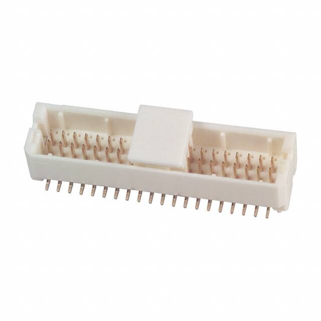
■Double Row Straight Pin header
B
A
Contact No.3
P=1
Contact No.1
Contact No. **-1
**
Indication of number
of contacts
Contact No. **
6.4
Contact No.2
0.2
0.7
4.6
5.4
Ø0.5
1.9
A
Nov.1.2021 Copyright 2021 HIROSE ELECTRIC CO., LTD. All Rights Reserved.
D
C
0.2
BPCB Footprints
A ±0.05
P=1±0.03
0.9±0.05
0.85±0.1
Contact No.1 marking
7.2 ±0.1
.1
+0 0
.7
Ø0
1.9±0.05
4±0.1
1.8 ±0.1
0.5±0.05
0.6±0.05
D±0.05
Note 1 : Shaded area must be free of any electrically conductive traces to avoid contact with soldered pin header terminations.
Note 2 : Required only for pin headers supplied with the positioning boss.
Unit : mm
Part No.
HRS No.
No. of contacts
A
B
C
D
DF20EF-10DP-1V
(52)
686-0055-0 52
10
14.0
17.3
16.6
----
DF20EF-20DP-1V
(52)
686-0056-0 52
20
19.0
12.3
11.6
----
DF20EF-30DP-1V
(52)
686-0057-0 52
30
14.0
17.3
16.6
----
DF20EF-40DP-1V
(52)
686-0058-0 52
40
19.0
22.3
21.6
----
DF20EF-50DP-1V
(52)
686-0053-0 52
50
24.0
27.3
26.6
----
DF20EG-10DP-1V
(52)
686-0059-0 52
10
14.0
17.3
16.6
15.7
DF20EG-20DP-1V
(52)
686-0060-0 52
20
19.0
12.3
11.6
10.7
DF20EG-30DP-1V
(52)
686-0061-0 52
30
14.0
17.3
16.6
15.7
DF20EG-40DP-1V
(52)
686-0062-0 52
40
19.0
22.3
21.6
20.7
DF20EG-50DP-1V
(52)
686-0054-0 52
50
24.0
27.3
26.6
25.7
Remarks
Without
boss
With boss
Note 1 : Order embossed tape packaging items by the reel. (1 reel contains 1,000 pieces)
【Specifications number】-*, (**)
Note 2 : Vacuum pick-up cap are included with embossed tape packaged connectors.
(52) : Gold plating,
embossed tape packaging
4
�DF20 Series●1mm Pitch Double Rows Low Profile Wire-to-Board Connectors
■Double Row Right angle Pin header
Contact No.3
Contact No.1
Contact No.**-1
Contact No.1
marking
Contact No.**
Contact No.2
B
P=1
6.2
0.2
A
0.2
C
1.4 +0.1
0
2.45 +0.1
0
3.8±0.05
1.4 +0.1
0
BPCB Footprints
2.75 ±0.05
Nov.1.2021 Copyright 2021 HIROSE ELECTRIC CO., LTD. All Rights Reserved.
**
A
5
5.5
Indication of
number of
contacts
0.6±0.05
P=1±0.03
A±0.05
0.75±0.1
D±0.05
Note : Shaded area must be free of any electrically conductive traces to avoid contact with soldered pin header terminations.
Unit : mm
Part No.
HRS No.
No. of contacts
A
B
C
D
DF20F-10DP-1H(52)
686-0027-2 52
10
24.0
27.5
26.2
25.8
DF20F-20DP-1H(52)
686-0028-5 52
20
29.0
12.5
11.2
10.8
DF20F-30DP-1H(52)
686-0029-8 52
30
14.0
17.5
16.2
15.8
DF20F-40DP-1H(52)
686-0030-7 52
40
19.0
22.5
21.2
20.8
Note : Order embossed tape packaging items by the reel. (1 reel contains 1,000 pieces)
Remarks
Without
boss
【Specifications number】-*, (**)
(52) : Gold plating,
embossed tape packaging
5
�DF20 Series●1mm Pitch Double Rows Low Profile Wire-to-Board Connectors
BEmbossed Carrier Tape Dimensions
●Straight pin header
Ø1
12 ±0.1
+0
0 .1
B ±0.1
0.2±0.05
R0.
75
1.7 +0.15
0
Nov.1.2021 Copyright 2021 HIROSE ELECTRIC CO., LTD. All Rights Reserved.
A ±0.3
C ±0.1
.5
1.75 ±0.1
2 ±0.1
4 ±0.1
1.5
(0.4)
+0.1
0
Unreeling direction
(7.9)
2±0.1
12±0.1
4±0.1
B ±0.1
0.2±0.05
R0
.75
1.7 +0.15
0
A ±0.3
C ±0.1
.1
+0
0
.5
Ø1
1.75 ±0.1
●Right angle pin header
(0.4)
1.5 +0.1
0
(7.4)
Unreeling direction
●Reel dimensions
16 ------- 17.5 16.4
DF20EF(G)-20DP-1V(52)
20
24 ------- 11.5 24.4
DF20EF(G)-30DP-1V(52)
30
32
28.4 14.2 32.4
DF20EF(G)-40DP-1V(52)
40
44
40.4 20.2 44.4
DF20EF(G)-50DP-1V(52)
50
44
40.4 20.2 44.4
DF20F-10DP-1H(52)
10
16 ------- 17.5 16.4
DF20F-20DP-1H(52)
20
24 ------- 11.5 24.4
DF20F-30DP-1H(52)
30
32
28.4 14.2 32.4
DF20F-40DP-1H(52)
40
44
40.4 20.2 44.4
2 ±0.5
D
Product name
label
6
Ø1.5mm diameter
feed hole depth
0.8
Ø21±
(Ø80)
C
±0
.2
B
Ø1
3
A
Ø380 ±2
No. of
Contacts
DF20EF(G)-10DP-1V(52)
10
Part No.
2±0.5
D
+2
0
�DF20 Series●1mm Pitch Double Rows Low Profile Wire-to-Board Connectors
BCrimping Precautions
■Items required prior to start crimping
The work-related documents shown below are required before starting the harness connections.
(The ● mark shows the document required.)
When the documents shown below are not available, ask our sales personnel to provide them.
Document Title
(1) Main unit of crimping machine
instruction manual
(2) Operating lnstructions for
Hand Tool
(3) Applicator Spare Parts
Identification
(4) Crimp Conditions
Nov.1.2021 Copyright 2021 HIROSE ELECTRIC CO., LTD. All Rights Reserved.
(5) Crimp Quality Standards
(6) Operating lnstructions for
Hand Tool
(7) Cable Assembly Procedure
Description
Automatic Crimping Hand Crimping
Machine
Tool
Explanation of main press
machine unit
●
−
Crimp operation
●
−
Explanation for Applicator
installation
Standard values of :
Crimp height ;
Tensile strength
Various standards for
crimping conditions
Inspection items of :
Crimp height ; Crimp operation
Tensile strength
●
−
Cable Assembly Procedure
Remarks
When purchasing main press
machine unit, it is bundled.
When purchasing Applicator,
it is bundled.
●
−
●
−
−
●
When purchasing Hand Tool,
it is bundled.
●
●
Ask our sales personal to
provide them.
■Tools
When crimping work is applied to our contacts, the tool designated by Hirose should be used.
Crimping work by using tools other than as designated must not be done because it may result in contact failure,
disconnection of cable, etc.
*The operating instructions manual is available for the crimping machine and the applicator.
Be sure to carefully read the operating instructions manual befor implementing the work.
■Applicable electric wires
Check that the electric wire to be used is in the range of application.
If you intend to use an electric wire other than the recommended one, ask our sales personnel.
[Precautions]
・Electric wires that are applicable for crimping connectors shall, principally, be the tin-plated stranded softcopper wire.
・Crimping of electric wires wherein single wires, polyester yarns, etc., exist and crimping of tin-coated wires should
be avoided.
・Avoid crimping two electric wires together.
・The setting values of crimp height (Note 1) may vary between tin-plated and gold-plated terminals even if the
same electric wires are used.
・The setting values of crimp height (Note 1) may vary depending on the difference in the core wire configuration
even if the computed cross-sectional area is the same.
Note 1 : The crimp height is an important item that determines crimping quality. We execute crimping tests for
each electric wire to ensure the optimal value for the crimp height with high precision, thereby ensuring
optimal setup values.
7
�DF20 Series●1mm Pitch Double Rows Low Profile Wire-to-Board Connectors
Handling Points
1. Recommended Soldering
Temperature Profile for IR
Reflow.
10(s) max
Temperature
(℃)
250
240
220
200
150
60 to 120(s)
60(s) max
Nov.1.2021 Copyright 2021 HIROSE ELECTRIC CO., LTD. All Rights Reserved.
100
60
120
180
240
300
Time(S)
Note 1 : Up to 2 cycles of reflow soldering are possible under the same conditions, provided
that there is a return to normal temperature between the first and second cycle.
Note 2 : The temperature indicates the board surface temperature at the points of
contacts with the connector terminals.
2. Recommended Manual
Soldering Conditions
Soldering temperature : 290°
C ±10°
C, Soldering time : within 3 sec.
3. Recommended Solder Screen
Thickness
0.15mm
4. Board Warping
Maximum of 0.03mm at the connector center section, with both ends of the connector as
reference points.
5. Cleaning Conditions
Refer to "Wire-to-Board Connector Use Handbook"
6. Wiring Termination Conditions
Refer to "Wire-to-Board Connector Use Handbook"
Crimp contacts should be handled with care as not to cause any deformation or damage
affecting the performance or termination.
7. Mating / un-mating precautions
Excessive twisting and pulling on wires during mating/un-mating should be avoided as it
may cause damage to connectors.
8. Precautions
Please refer to the following documents.
■ Crimp Quality Standard (ETAD-H0929-00)
■ Cable Assembly Procedure (ETAD-H0930-00)
■ Mating/Unmating Operation Instruction Manual (ETAD-H0997-00)
■ User Guide for Wire-to-Board Connector
®
8
2-6-3,Nakagawa Chuoh,Tsuzuki-Ku,Yokohama-Shi 224-8540,JAPAN
TEL: +81-45-620-3526 Fax: +81-45-591-3726
http://www.hirose.com
http://www.hirose-connectors.com
The characteristics and the specifications contained herein are for reference purpose. Please refer to the latest customer drawings prior to use.
The contents of this catalog are current as of date of 02/2021. Contents are subject to change without notice for the purpose of improvements.
�


 工商网监
湘ICP备2023018690号
工商网监
湘ICP备2023018690号
