•
•
•
•
•
•
•
Ideal for 303.825 MHz Remote Control and Security Transmitters
Very Low Series Resistance
Quartz Frequency Stability
Complies with Directive 2002/95/EC (RoHS)
Tape and Reel Standard per ANSI/EIA-481
Moisture Sensitivity Level: 1
AEC-Q200 Qualified
RO3104E
RoHS
Compliant
303.825 MHz
SAW
Resonator
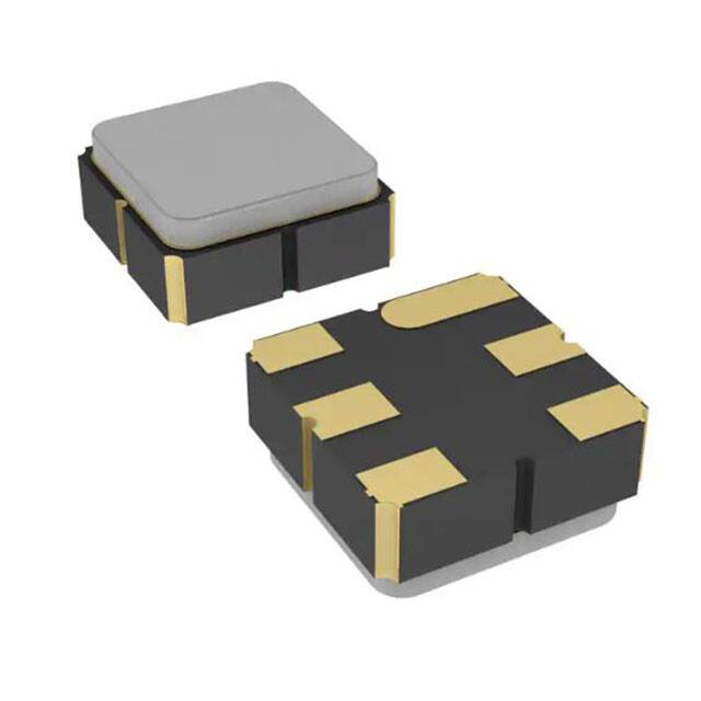
The RO3104E is a true one-port, surface-acoustic-wave (SAW) resonator in a surface-mount ceramic case.
It provides reliable, fundamental mode quartz frequency stabilization of fixed-frequency transmitters operating
at 303.825 MHz. This SAW is designed specifically for AM transmitters used in wireless security and remote
control applications.
Absolute Maximum Ratings
Rating
Value
Units
CW RF Power Dissipation (See Typical Test Circuit)
0
dBm
DC Voltage Between Terminals (Observe ESD Precautions)
12
VDC
Case Temperature
-40 to +85
°C
+260
°C
Soldering Temperature (10 seconds, 5 cycles maximum)
SM3030-6 Case
Electrical Characteristics
Characteristic
Frequency, +25 °C
Sym
Nominal Frequency
Tolerance from 303.825 MHz
Insertion Loss
Quality Factor
Temperature Stability
Frequency Aging
Notes
fC
IL
1.35
Unloaded Q
QU
10000
50 Loaded Q
QL
Turnover Temperature
TO
Turnover Frequency
fO
fC
Frequency Temperature Coefficient
FTC
0.032
Absolute Value during the First Year
|fA|
Maximum
Units
303.900
MHz
±75
kHz
2.0
dB
40
°C
1400
10
25
10
1.0
ppm/°C2
ppm/yr
M
16
Motional Inductance
LM
85
µH
Motional Capacitance
CM
3.2
fF
Transducer Static Capacitance
CO
3.2
pF
LTEST
85
nH
Motional Resistance
RM
Test Fixture Shunt Inductance
Lid Symbolization
Standard Reel Quantity
Typical
303.750
fC
DC Insulation Resistance between Any Two Terminals
RF Equivalent RLC Model
Minimum
690, YWWS
Reel Size 7 Inch
500 Pieces/Reel
Reel Size 13 Inch
3000 Pieces/Reel
CAUTION: Electrostatic Sensitive Device. Observe precautions for handling.
NOTES:
1. The design, manufacturing process, and specifications of this device are subject to change.
2. US or International patents may apply.
3. RoHS compliant from the first date of manufacture.
©2010-2014 by RFM Integrated Device, Inc.
RO3104E (R) 12/07/2021
Page 1 of 3
www.rfmi.co
�Pin
The SAW resonator is bidirectional and
may be installed with either orientation.
The two terminals are interchangeable
and unnumbered. The callout NC
indicates no internal connection. The NC
pads assist with mechanical positioning
and stability. External grounding of the NC
pads is recommended to help reduce
parasitic capacitance in the circuit.
B
NC
2
Terminal
3
NC
4
NC
5
Terminal
6
NC
6
690
YWWS
A 2
5
E
F
The curve shown accounts for resonator contribution only and does not
include external LC component temperature effects.
fC = f O , T C = T O
0
G
C
1
Temperature Characteristics
Connection
1
0
-50
-50
-100
-100
-150
-150
(f-fo ) / fo (ppm)
Electrical Connections
-200
-80 -60 -40 -20
H
6
1
5
2
4
3
-200
0 +20 +40 +60 +80
T = TC - T O ( °C )
I
Characterization Test Circuit
Inductor LTEST is tuned to resonate with the static capacitance, CO, at FC.
3
4
D
J
6
1
From 50
Network Analyzer
5
2
4
3
To 50
Network Analyzer
K
L
N
K
Power Dissipation Test
N
O
N
M
M
50 Source
at F C
Case and Typical PCB Land Dimensions
Ref
A
B
C
D
E
F
G
H
I
J
K
L
M
N
O
Min
2.87
2.87
1.12
0.77
2.67
1.47
0.72
1.37
0.47
1.17
mm
Nom
3.00
3.00
1.25
0.90
2.80
1.60
0.85
1.50
0.60
1.30
3.20
1.70
1.05
0.81
0.38
Max
3.13
3.13
1.38
1.03
2.93
1.73
0.98
1.63
0.73
1.43
Min
0.113
0.113
0.044
0.030
0.105
0.058
0.028
0.054
0.019
0.046
P INCIDENT
Low-Loss
Matching
Network to
50
P REFLECTED
Inches
Nom
0.118
0.118
0.049
0.035
0.110
0.063
0.033
0.059
0.024
0.051
0.126
0.067
0.041
0.032
0.015
Max
0.123
0.123
0.054
0.040
0.115
0.068
0.038
0.064
0.029
0.056
1
6
5
4
Typical Low-Power Transmitter Application
Modulation
Input
200k
+9VDC
C1
47
L1
(Antenna)
1
6
2
3
5
4
C2
ROXXXXC
Bottom View
RF Bypass
470
Typical Local Oscillator Application
Output
200k
C1
Equivalent RLC Model
+VDC
L1
0.05 pF*
Cp
Lm
3
Example Application Circuits
+VDC
Rm
2
1
Co = Cp + 0.05 pF
6
2
3
5
4
C2
*Case Parasitics
ROXXXXC
Bottom View
RF Bypass
Cm
©2010-2014 by RFM Integrated Device, Inc.
RO3104E (R) 12/07/2021
Page 2 of 3
www.rfmi.co
�Recommended Reflow Profile
1. Preheating shall be fixed at 150~180ºC for 60~90 seconds.
2. Ascending time to preheating temperature 150ºC shall be 30 seconds min.
3. Heating shall be fixed at 220ºC for 50~80 seconds and at 260ºC +0/-5ºC peak (10 seconds).
4. Time: 5 times maximum.
©2010-2014 by RFM Integrated Device, Inc.
RO3104E (R) 12/07/2021
Page 3 of 3
www.rfmi.co
�
很抱歉,暂时无法提供与“RO3104E”相匹配的价格&库存,您可以联系我们找货
免费人工找货