0
登录后你可以
  • 下载海量资料
  • 学习在线课程
  • 观看技术视频
  • 写文章/发帖/加入社区
会员中心
创作中心
发布
  • 发文章

  • 发资料

  • 发帖

  • 提问

  • 发视频

创作活动
HS21R-5(71)

HS21R-5(71)

  • 厂商:

    HRS(广濑)

  • 封装:

    -

  • 描述:

    CONN RCPT MALE 5P SOLDER CUP

  • 详情介绍
  • 数据手册
  • 价格&库存
HS21R-5(71) 数据手册
Metal Shell Circular Connectors HS Series Introduction ·‌The HS series is generally called “metal connector”, and is the most widely used standard multi-pin circular connector. ·‌Being sturdy and simple in construction, the HS connectors are stable mechanically and electrically and are employed by NTT and set manufacturers as standard parts. Material Part Material Finish Shell Copper compound metal Nickel plated Insulator Synthetic resin ----------------- Male contacts Brass Female contacts Brass or phosphor bronze Nickel plated Ordering information HS 21 P A - 2 A q w e r t y qModel name: HS stands for HIROSE STANDARD. wShell size: ‌The shell size is expressed as the outside diameter of the plug fitting section (insulator) with seven types: 12, 14, 16, 21, 25, 28 and 35. eShell type: The shell is classified into the following types. P : Plug R : Receptacle J : Jack RC : Receptacle cap rShell model change mark: Each time the shell undergoes a model change, it is marked as A, B or C. tNumber of contacts y‌Contact arrangement change mark: When the contact fitting section or contact arrangement undergoes a change, it is marked as A, B, C....after the number of contacts. 2014.12w 1 HS Series●Metal Shell Circular Connectors Plug Caulking (Representative example) HS21P−2(71) HRS No. 101-0002-0 71 2 ØA ØB ØC D L HS12P-2(71) Part No. 12 18 7 M15.5×1 38 13.5 21.5 8.5 M19×1 43 101-0013-7 71 HS14P-2(71) 101-0030-6 71 HS16P-2(71) 101-0031-9 71 HS16P-3(71) 101-0034-7 71 HS16P-4(71) 101-0275-3 71 HS16P-5(71) 101-0053-1 71 HS21P-2(71) 101-0060-7 71 HS21P-3(71) 101-0066-3 71 HS21P-4(71) 101-0669-1 71 HS21P-5(71) 101-0074-1 71 HS21P-6(71) 101-0075-4 71 HS21P-7(71) 101-0076-7 71 HS21P-8(71) 101-0369-5 71 HS21P-10(71) 101-0115-7 71 HS25P-2(71) 101-0117-2 71 HS25P-3(71) 101-0122-2 71 HS25P-6(71) 101-0128-9 71 HS25P-8(71) 101-0129-1 71 HS25P-10(71) 101-0154-9 71 HS28P-4(71) 101-0158-0 71 HS28P-8(71) 101-0187-8 71 HS35PB-16(71) 101-0189-3 71 HS35PB-20(71) 15.5 21 28 M25×1 50 10 49 25 32 28 38 35 46 M29×1 54.5 16 M34×1 64.5 19 M41×1 71.5 HS Series●Metal Shell Circular Connectors Receptacle 3-ØE HS21R−2(71) HRS No. Part No. 101-0007-4 71 HS12R-2(71) 101-0016-5 71 HS14R-2(71) 101-0040-0 71 HS16R-2(71) 101-0041-2 71 HS16R-3(71) 101-0042-5 71 HS16R-4(71) 101-0448-0 71 HS16R-5(71) 101-0084-5 71 HS21R-2(71) 101-0089-9 71 HS21R-3(71) 101-0091-0 71 HS21R-4(71) 101-0093-6 71 HS21R-5(71) 101-0095-1 71 HS21R-6(71) 101-0096-4 71 HS21R-7(71) 101-0097-7 71 HS21R-8(71) 101-0370-4 71 HS21R-10(71) 101-0130-0 71 HS25R-2(71) 101-0131-3 71 HS25R-3(71) 101-0135-4 71 HS25R-6(71) 101-0137-0 71 HS25R-8(71) 101-0138-2 71 HS25R-10(71) 101-0163-0 71 HS28R-4(71) 101-0166-8 71 HS28R-8(71) (Representative example) ØB ØC D ØE ØF L 23 19 M15.5×1 2.1* 14 22.5 M N 1.5 16.5 32 25.5 M19×1 41 33 M25×1 19 25 23 26.5 16 19.5 3.2 2 24.5 46 37 M29×1 29 17.5 19.5 26.5 51 43 M34×1 32 19 Note: 1.6Ø flat head screw is recommended for mounting. 3 HS Series●Metal Shell Circular Connectors Receptacle HS35RA−16(71) HRS No. (Representative example) Part No. 101-0200-4 71 HS35RA-16(71) 101-0201-7 71 HS35RA-20(71) B C D ØE ØF L M N 43 35 M41×1 3.2 40 31 21.5 2.5 Jack (Representative example) HS21J-2(71) HRS No. Part No. 101-0010-9 71 HS12J-2(71) 101-0047-9 71 HS16J-2(71) 101-0048-1 71 HS16J-3(71) 101-0049-4 71 HS16J-4(71) 101-0416-3 71 HS16J-5(71) 101-0104-0 71 HS21J-2(71) 101-0107-9 71 HS21J-5(71) ØB ØC D L 18 7 M15.5×1 44.5 21.5 8.5 M19×1 50 28 10 M25×1 57 Cap for Receptacle (Representative example) HS21RC(72) HRS No. Part No. ØA B 101-0011-1 72 HS12RC(72) 18 M15.5×1 101-0027-1 72 HS14RC(72) 21.5 M19×1 101-0109-4 72 HS21RC(72) M25×1 28 C 7 HRS No. Part No. ØA B 101-0148-6 72 HS25RC(72) 32 M29×1 101-0174-6 72 HS28RC(72) 38 M34×1 101-0207-3 72 HS35RC(72) 46 M41×1 C 7 9 Note: Part No. HS14RC is possible to use as cap of size 16. 4 HS Series●Metal Shell Circular Connectors Terminal Arrangement Shell size Shell size 12 14 No. of contacts 2 No. of contacts Withstanding voltage AC 1000V a minute Current rating 2 Withstanding voltage AC 1000V a minute 7A Current rating 7A Insulation resistance 1000 Mø MIN. Insulation resistance 1000 Mø MIN. Contact resistance 5 mø MAX. Contact resistance 5 mø MAX. Solder cup dia. Ø1.5 Solder cup dia. Ø1.5 Shell size 16 No. of contacts 2 3 4 5 AC 1000V a minute Withstanding voltage 7A Current rating Insulation resistance 1000 Mø MIN. Contact resistance 5 mø MAX. Ø1.8 Solder cup dia. Ø1.5 Shell size 21 No. of contacts 2 3 4 AC 1000V a minute Withstanding voltage 10A Current rating 6 7A Insulation resistance 1000 Mø MIN. Contact resistance 5 mø MAX. Ø2.0 Solder cup dia. 5 AC 500V a minute AC 1000V a minute Ø1.5 Shell size 21 No. of contacts 7 Current rating 7A 10 4A 3A 1000 Mø MIN. Insulation resistance 5 mø MAX. Contact resistance Solder cup dia. 8 AC 1000V a minute Withstanding voltage Ø1.5 Ø1.2 Ø1.5 5 HS Series●Metal Shell Circular Connectors Shell size 25 2 No. of contacts 3 6 AC 1000V a minute Withstanding voltage 10A Current rating 1000 Mø MIN. Insulation resistance 5 mø MAX. Contact resistance Ø2.0 Solder cup dia. Shell size Shell size 25 28 10 No. of contacts Withstanding voltage 4A 5 mø MAX. Ø1.2 Solder cup dia. Withstanding voltage 7A 10A 1000 Mø MIN. Insulation resistance 5 mø MAX. Contact resistance Solder cup dia. 8 AC 1000V a minute Current rating 1000 Mø MIN. Contact resistance 4 No. of contacts AC 1000V a minute Current rating Insulation resistance 8 Ø1.8(Receptacle: Ø1.5) Ø2.0 Shell size 35 16 No. of contacts 20 AC 1000V a minute Withstanding voltage 4A Current rating 1000 Mø MIN. Insulation resistance 5 mø MAX. Contact resistance Ø1.2 Solder cup dia. Note: 1. Contact arrangements are shown at the fitting section of Plug. 2. Insulation resistance is measured at DC 500V. 3. Contact resistance is measured at DC 1A. 4. Withstanding voltage is shown as test voltage, so that the preferable value for daily operation is about one-third of each figure. ® 6 2-6-3,Nakagawa Chuoh,Tsuzuki-Ku,Yokohama-Shi 224-8540,JAPAN TEL: +81-45-620-3526 Fax: +81-45-591-3726 http://www.hirose.com http://www.hirose-connectors.com The characteristics and the specifications contained herein are for reference purpose. Please refer to the latest customer drawings prior to use. The contents of this catalog are current as of date of 12/2014. Contents are subject to change without notice for the purpose of improvements.
HS21R-5(71)
1. 物料型号:HS系列,包括不同尺寸和类型的连接器,如插头(Plug)、插座(Receptacle)、插座帽(Receptacle cap)和插孔(Jack)。

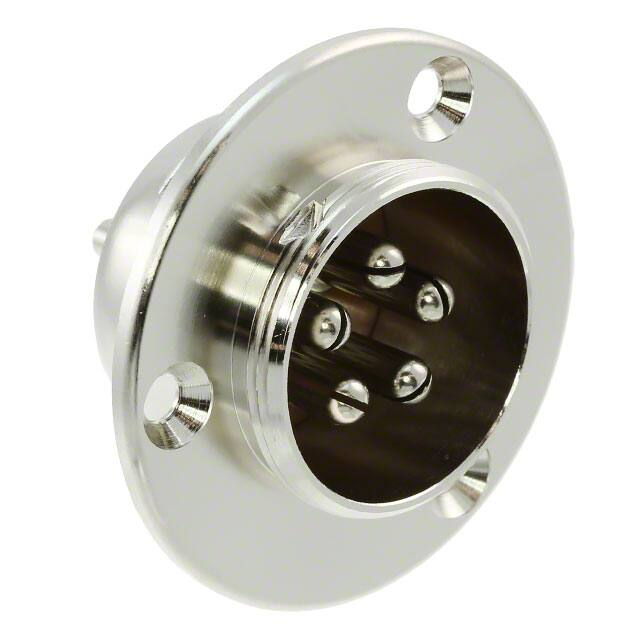
2. 器件简介:HS系列通常被称为“金属连接器”,是最广泛使用的标准多针圆形连接器。它们结构坚固简单,机械和电气性能稳定,被日本电信电话公司(NTT)和设备制造商作为标准部件采用。

3. 引脚分配:文档提供了不同型号的连接器的引脚数量和排列,例如HS12P-2(71)、HS21P-2(71)等。

4. 参数特性:包括耐电压、电流额定值、绝缘电阻、接触电阻和焊盘直径等。

5. 功能详解:文档详细描述了连接器的机械和电气特性,如耐电压测试电压、电流额定值、绝缘电阻和接触电阻的测量条件。

6. 应用信息:HS系列连接器广泛应用于需要高可靠性和稳定性的场合。

7. 封装信息:提供了不同型号连接器的尺寸和安装信息,如外壳尺寸、安装螺丝推荐使用1.6mm平头螺丝。
HS21R-5(71) 价格&库存

很抱歉,暂时无法提供与“HS21R-5(71)”相匹配的价格&库存,您可以联系我们找货

免费人工找货