�* Please visit the product pages on our website for the most up-to-date product information
ABOUT SWITCHCRAFT, INC.
Switchcraft, Inc. was established in 1946 to manufacture
jacks, plugs and switches, from its original plant located
on West Diversey Street in Chicago. The company moved
to a larger facility at 1328 North Halsted Street in 1948, and
in 1958, the operation moved to 5555 North Elston Avenue,
which is still the headquarters of the corporation.
CATALOG SECTIONS
Connectors . . . . . . . . . . . 1-78
Jacks & Plugs . . . . . . . . . 79-162
Jack Panels . . . . . . . . . . . 163-238
Patch Cords and
Molded Cable
Assemblies . . . . . . . . . . . 239-268
In the 185,000-square-foot Chicago facility, Switchcraft
manufactures electronic and elecromechanical components, including:
• Jacks
• Plugs
• Connectors
• Jackfields
• Patch Panels
• Patch Cords
• Switches
• EAC Power
• Molded Cable Assemblies
Receptacles
Switches . . . . . . . . . . . . . 269-318
Index by Part Number . . . 319-328
With a basic line of over 5,000 standard products and
thousands of variations, Switchcraft is proud to offer a
limited lifetime warranty on all products.
Switchcraft markets products both domestically and
internationally through a network of manufacturers’
representatives and independent distributors.
In 1999, Switchcraft acquired the Conxall Corporation
located in Villa Park, Illinois. Conxall was founded in 1971
as a manufacturer of sealed connectors for the marine
industry. Today, the company offers a broad line of custom
cable assemblies and connectors used in marine, industrial,
sensor, communications and transportation applications.
For more information contact Conxall at (630) 834-7504, or
visit their website at www.conxall.com.
LIMITED LIFETIME WARRANTY
Switchcraft warrants all of its products to be of sound
design, good materials and workmanship at the time of
manufacture.
Switchcraft will repair or replace at its discretion any product
proven to be defective under normal use.
Switchcraft’s liabilty under the terms of this warranty is limited
to the repair or replacement of defective products which
have not been damaged through accident, abuse, misuse
or unauthorized repair. Switchcraft shall in no case be liable
for special or consequential damages of any nature.
Visit us on the net:
www.switchcraft.com
Switchcraft®. . .
Consistently Excellent Since 1946sm
ABOUT
Switchcraft is a leading supplier of a broad line of components
for the audio/video, broadcast, telecommunication,
computer, medical, military, appliance, transportation and
instrumentation industries.
�i
PHONE: 773 792-2700
* Please visit the product pages on our website for the most up-to-date product information
TABLE OF CONTENTS
CONNECTORS AND RECEPTACLES
Q-G® XLR CONNECTORS.........................................................1-30
Q-G® Connector Part Numbering System....................................2
Professional Series Q-G® Connector Part Numbering System .......2
Q-G® Audio Connectors A, AA, AND QGP Series....................3-4
Part Numbers - Male Cord Plugs/Female Cord Plugs ..................4
Q-G® Color Flex Reliefs/Flex Relief .............................................5
AAA XLR Connectors ................................................................6-7
P(*)M Gooseneck Plug, P(*)F Microphone Plug,
R(*)MZ Cord Plug, R(*)FZ Cord Plug ...........................................8
D(*)M, D(*)F and D(*)FD Receptacles ..........................................9
T(*)F and T(*)FM Cord Plug With On-Off Switch ..........................9
B(*)F Receptacle, C(*)F Receptacle, B(*)M Receptacle,
C(*)M Receptacle ........................................................................10
E Series Receptacles.............................................................11-15
EH Series Receptacles ...............................................................16
PQG® Receptacles................................................................17-18
PD Series - Plastic Panel Mount ...........................................19-21
Y3F, Y3FPC, Y3FDPC and Y3MPC Receptacles ........................22
F Series Receptacles ............................................................23-24
Q-G® Adapters, Accessories .....................................................25
Q-G® Wall Plate Receptacles ....................................................26
Q-G® Connector-Adapters.....................................................27-28
S*FM Audio Connector-Adapter .................................................28
Audio “Y” Adapters .....................................................................28
DMX Adapter ..............................................................................29
Q-G® Connector-Adapter Receptacles ......................................30
Z Matching Transformers, Series M(*)M, Series L(*)MN ............30
TINI Q-G® MINIATURE CONNECTORS .................................31-37
Tini Q-G® Audio Adapters ..........................................................31
TB(*)M AND TB(*)MB Receptacle,TLP(*) Looping Plug, Straight
Female Looping Plug, Reverse Gender TQG Series .................33
TRA(*)M PC Mount Male Receptacle ........................................34
TRASM*M, TRAPC*M Series ...............................................34-36
TY(*)F and TY(*)FPC Receptacles,TYEF Escutcheons,
TQG(*)F and TQG(*)M Connector Inserts, TBA(**)
Audio Adapter .............................................................................37
HPC HIGH POWER AUDIO CONNECTORS ...........................38-40
EN3TMini WEATHERTIGHT CONNECTOR SERIES ..............41-45
2 - 8 pin Cord Connector, 9 - 18 pin Cord Connector ................43
2 - 8 pin Panel Connector, 9 - 18 pin Panel Connector .............44
2 - 8 pin Inline Connector, 2 - 8 pin Overmolded Cord
and Inline Connector ..................................................................45
DIN CONNECTORS .................................................................46-55
Plugs .....................................................................................46-48
Panel Mount Receptacles .....................................................48-50
Right Angle PC Mount Receptacles .....................................51-52
Mini-DIN Right-Angle Receptacles, Right-Angle, PC Mount
Receptacles ..........................................................................47-53
SMD Series ................................................................................54
DMD Series ................................................................................55
USB CONNECTORS ................................................................56-57
IEEE 1394 FIREWIRE CONNECTORS ...................................58-59
SLIM-LINE CONNECTORS ......................................................60-64
Cord Plugs .................................................................................60
Slim-Line Connector Part Numbering System, Cable Clamp and
Strain Relief ................................................................................61
SL40-SL41 Male/Female Cord Plugs .........................................62
SL10-SL17 Male/Female Receptacles .......................................63
www.switchcraft.com
SL18 Male/Female Receptacles ................................................64
CB CONNECTORS MICROPHONE CONNECTORS,
MINI-CON MINIATURE CONNECTORS .......................................65
HP75BNC SERIES BNC CONNECTORS ................................66-67
EAC RECEPTACLES ...............................................................68-77
RAPC322 POWER INLET SOCKET .............................................78
JACKS AND PLUGS
JACK SCHEMATICS ................................................................79-80
1/4" LONG FRAME TELEPHONE JACKS ...............................81-85
1/4" Jack Blocks .........................................................................86
BANTAM TYPE® JACKS ..........................................................87-90
TT-JAX® (.173") Telephone Jacks Bantam Type® ................87-88
TT-JAX® (.173") Telephone Twin Jacks Bantam Type® .............89
TT-JAX® (.173") Telephone Triple Jacks Bantam Type® ............90
RTT Series Miniature Telephone Jacks,
Right Angle, PC Mount .........................................................91-92
.177" Enclosed Jacks .................................................................93
LITTEL JAX® 2- AND 3-CONDUCTOR,
1/4" PHONE JACKS ...............................................................94-109
Hi-D Jax® 2- and 3-Conductor .............................................96-99
Spring Lock PC Terminals for Hi-D Jax® .................................100
SN Series, RA Series Right-Angle Phone Jacks ..............101-105
500 Series Jack Covers ...........................................................106
Series E (Locking) and Thick Panel Phone Jacks ...................107
1/4" Extension Jacks and 1/4" Speaker Jacks .........................108
1/4" Shielded Phone Jacks, SF-Jax®
Short Frame Jacks ...................................................................109
.141" MINIATURE PHONO JACKS .......................................109-111
3.5MM DUAL STEREO JACK ...............................................112-113
3.5MM SINGLE MONO AND STEREO JACKS ...................114-118
3.5MM SINGLE MONO JACKS ...................................................119
2.5MM SINGLE MONO AND STEREO JACKS ..........................120
.101" SUBMINIATURE PHONE JACKS ...............................121-122
RCA PHONO JACKS AND PHONO JACK SETS ................123-129
RIGHT ANGLE MINIATURE POWER JACKS ......................130-133
STRAIGHT MINIATURE POWER JACKS ............................134-135
VJ SERIES VIDEO JACKS ..........................................................136
MVJ SERIES VIDEO JACKS .......................................................137
MIL-TYPE 1/4" PHONE PLUGS ...........................................138-141
Littel Plug® Phone Plugs .........................................................139
MIL-TYPE 1/4" EXTENSION JACKS ...........................................142
® Registered trademark of Switchcraft, Inc.
Note: Contact your Switchcraft Representative for price and delivery
�ii
FAX: 773 792-2129
* Please visit the product pages on our website for the most up-to-date product information
TELEPHONE PATCH ADAPTERS ..............................................142
BANTAM TYPE MINIATURE TELEPHONE PLUGS ............143-144
3.5MM HEAVY DUTY STEREO PLUGS .....................................156
.141" MINIATURE PHONE PLUGS .............................................157
.097" SUBMINIATURE PHONE PLUGS ......................................158
AUDIO ADAPTERS .....................................................................159
RCA PHONO PLUGS ...........................................................160-161
MINIATURE POWER PLUGS ......................................................162
JACK PANELS, PATCH PANELS, PATCH KITS AND
JACKFIELDS
AUDIO PATCHBAYS .............................................................163-190
Professional Punchdown Terminal (PPT) ..................................163
Front Access MTPFA/TTPFA Series ..................................164-165
MTP48K Wired Audio Series .............................................166-167
TTP96K Wired Audio Series ..............................................168-169
MTPH/TTPH Harness Audio Series...................................170-173
MTPBP/TTPBP Backpanel Series .....................................174-175
EZ NORM Patchbay Series ...............................................176-177
TT96 EDAC Series.............................................................178-179
TTP96K Patchkit Series ....................................................180-181
MT48K/MT52K Patchkit Series ..........................................182-183
MT48/MT52 Patchbay Series.............................................184-185
TTP96AS Patchbay Series ................................................186-187
Q-G®XLR Patchbay Series................................................188-189
HPC Patchbay Series................................................................190
RS 422 DATA PATCHBAY SERIES ......................................191-192
VIDEO PATCHBAYS .............................................................193-201
VPP Video Patchbay Series ..............................................193-195
MVP Midsize Video Patchbay Series ................................196-198
VAP Video/Audio Patchbay Series ....................................199-200
MBPK Video/Audio Patchbay Series ........................................201
TELECOM TYPE JACK PANELS .........................................202-238
Long Frame (1/4")Single Row Telephone Jack Panels ....202- 203
Long Frame (1/4") Twin Row Jack Panels ........................204-205
Long Frame (1/4") Modular Twin Row Jack Panels ..........206-209
Long Frame (1/4") Modular 3 Row Jack Panels .......................210
TT-Jax® (.173") Jack Panel Series 1600, A1600,
B1600, C1600 ...................................................................211-214
Modular TT-JAX® (.173") Panels Blank Series TT51, TT53, TT56, TT59 .....................................215
TT Module Inserts - Series TT91, TT92 And TT93 ..................216
Modular TT-Jax® (.173") Jack Panels -Series TT5102000,
PATCH CORDS AND
MOLDED CABLE ASSEMBLIES
MOLDED CABLE ASSEMBLIES ..........................................239-261
Design Materials and Features ................................................239
3.5MM Molded Cables .............................................................240
Power-Plug Battery Charger Plugs and Jacks .........................241
Power Plugs and Jacks Part Numbering System .....................242
EN3T MINI Weathertight Overmolded Cable Assemblies ........243
Cordette® and Cord Switch Assemblies ....................................44
Cordette® Switches .................................................................245
DIN Plugs ..........................................................................246-248
MIDI Cables ..............................................................................249
Miniature, Shielded, Molded Tini Q-G® Plugs .........................250
Molded Cable Assemblies for Multi-Pin Interconnection
Part Numbering System ...........................................................251
Standard Multi-Pin Interconnection Cables ..............................252
Micro Plug® Subminiature Phone Plugs ..................................253
Tini Plug® Miniature Phone Plugs ...........................................254
Phono Plugs and Phono Extension Jacks ...............................255
Tini-Extension® Jacks ..............................................................256
Littel Plug® Phone Plugs ..................................................256-257
Extension Jax® Phone Jacks ...................................................257
Cable Clamp Bands, “Y” Junctions ..........................................258
Part Numbering System ...........................................................259
Standard Cable Guide ..............................................................260
Cross Reference Guide ............................................................261
AUDIO/VIDEO PATCHCORDS ............................................262- 267
1/4" Longframe Telephone Patch Cords, MIL Type 1/4" Patch
Cords ........................................................................................262
Combination Patch Cords and MIL Type
1/4" Twin Patch Cords .............................................................263
Miniature TT® Braided Patch Cords .......................................264
Miniature TT® Molded Patch Cords
and Telephone Couplers ..........................................................265
Video Patch Cords ...................................................................266
Broadcast Series 3-Conductor Bantam TT Patch Cords,
Analog-AES/EBU Audio, and RS422 Patching ........................267
SWITCHES
PUSHBUTTON SWITCHES
IBS Series Miniature Keyboard Switches .................................269
IBS Keyboard Switch Pushbuttons ...........................................270
US Series Uniswitch® Switches ...............................................271
BXR Series Box Switch® Switches ..........................................272
Button-Switch® Switches, Tini-Switch® Switches ...................273
Littel-Switch® Switches ............................................................274
Hi-D Switch® PC Mount Switches, DA-Switch Switches .........275
Cord-Switch® Cord Switches, Cordette® Cord Switches ........276
SWITCHCRAFT, INC. 5555 N. Elston Ave. • Chicago, IL 60630
TABLE OF CONTENTS
1/4" COMMERCIAL PHONE PLUGS LITTEL-PLUG® PLUGS .......................................................145-147
Silent-Plug And Lug® Phone Plugs .........................................148
Audio Loudspeaker and Heavy Duty 1/4"
Commercial Phone Plugs .................................................149-150
.206" Commercial Phone Plugs ...............................................151
1/4" Miti-Plug® Audio Plugs .....................................................152
1/4" Flat Plug Phone Plugs ......................................................153
Right-Angle Phone Plugs .........................................................154
1/4" Lock-Extension Jacks And Plugs ......................................155
TT5202000, TT5502000, TT5602000 ...............................217-218
TT-Jax® (.173") Twin Row and Three Row Jack Panels ....219-220
TT-Jax® (.173") Connectorized Jackfields - Series TT,
2-wire, 4-wire, 6-wire .........................................................221-229
TT® Lamps and Jewel Assemblies ..........................................230
Longframe Switchboard Switches ............................................231
Dummy Plugs and Hole Plugs .................................................232
TT® (Bantam) Circuit Guard Plugs ..........................................233
Miniature, Dummy Plugs, Hole Plugs .......................................234
Designation Strips .............................................................235-236
Kwik-Change® Designation Strips (Double Height) .................237
X-Wide® Vertical Designation Strips ........................................238
�iii
PHONE: 773 792-2700
TABLE OF CONTENTS
* Please visit the product pages on our website for the most up-to-date product information
Push-Lite® Switches and Indicators .................................277-281
Series PL9000 - PL® Indicators, Pushbutton/Indicator
Screens, Color Filter Snap-Insserts, Optional
Mounting Barriers, Light Divider ...............................................278
Part Numbering System ...........................................................279
Outline Dimensions ...........................................................280-281
SLIDE SWITCHES ...............................................................282-290
General Purpose Slide Switches ......................................284-287
Miniature Slide Switches ...................................................288-290
Side-Slide®/Miniature Slide Switches ......................................290
European Line Voltage Selector Switches ........................291-293
LEVER SWITCHES ..............................................................294-298
GENERAL PURPOSE STACK SWITCHES .........................299-300
MULTIPLE STATION SWITCHES .........................................301-302
Littel® Multi Switch ............................................................303-308
DW Multi-Switch ................................................................309-311
Tini® DW Multi-Switch ......................................................312-313
IBS Multi-Switch - Series IBS ...........................................314-315
Multi-Switch Pushbuttons ..................................................316-317
INDEX BY PART NUMBER ...................................................319-328
www.switchcraft.com
® Registered trademark of Switchcraft, Inc.
Note: Contact your Switchcraft Representative for price and delivery
�CONNECTORS & RECEPTACLES
Q-G® CONNECTORS
FAX: 773 792-2129
1
* Please visit the product pages on our website for the most up-to-date product information
SECTIONALIZED VIEW - A3F Plug to B3M Receptacle
MALE RECEPTACLE
FEMALE CONNECTOR
Panel
Ground Terminal
Latch Lock
Insert set screw
(Shell ground)
Ground Terminal
Pin
Cable Clamp
Strain Relief
Insert
Shell
DESIGN FEATURES
CONSTRUCTION: Sturdy, die-cast zinc with satin nickel
finish or Black-Velvet® finish to withstand hard use – even
abuse. Vel-Tone non-reflective finish on QGP connectors only.
INSERT INSULATION: High-impact, molded thermoplastic
provides high dielectric strength, and superior insulation
resistance.
Field-proven Switchcraft Q-G ® (Quick-Ground) 3- through
7-contact audio connectors with ground terminal and ground
contactors are available in a wide range of plugs and
receptacles for microphones, test equipment, instrumentation,
computers, video cameras, mixing consoles, tape recorders,
PA and sound reinforcement, stereo systems and many more
applications.
Switchcraft Q-G® connectors feature a separate ground-terminal
electrically integral with connector shell. Ground continuity
between mating plugs is automatically accomplished through
exclusive “Dual Point” grounding system. Socket and pin
assemblies utilize “wedge-action” to insure firm, reliable
positioning in connector shell. Inserts are easily removable for
wiring and soldering. High-impact thermoplastic insures long
reliable insert assembly life. Female connectors have latch lock
feature to hold connectors firmly together. Plugs and receptacles
are mechanically keyed for proper mating. Q-G (*) Series 3-,
4-, 5-, 6-, and 7-pin/contact connectors offer 4-,
5-, 6-, 7-, and 8-pin contact versatility when ground-terminal is
used. Switchcraft QGP connectors; are compatible with
3- and 4-contact (Neutrik, Amphenol 91-850 and Excellite
91-450 Series, and Cannon XLR-3, XLR-4): 5-contact (Neutrik,
Cannon XLR-5 and Amphenol Excellite 91-450 Series).
Captive Design® Insert Screws
LOCKING: Latchlock on female plugs and receptacles locks
into groove in mating male connector to prevent accidental
disconnect. Manual release of latchlock is required to
separate connectors. Q-G connectors are also available with
FAS-DISCONNECT detent in place of latchlock. QGP has diecast latchlock.
FAS-DISCONNECT: FAS-DISCONNECT detent permits
immediate disconnect of locked connectors with a 4-pound
(1.8 kg) force. FAS-DISCONNECT connectors are not
recommended for use in situations where strong or violent
pulls on cable may occur and cause accidental disconnect.
Available on Q-G connectors only.
Insert screw engages as any conventional screw, except it is
lefthand threaded. To disassemble the connector, turn screw
counterclockwise down into insert (see illustration).
DUAL PRESSURE PLATES: A*F and A*M Series provides
secure cable lock and strain relief for all standard size cables.
FLEX RELIEF: TPR cable flex relief bushings on cord plugs
are keyed to shell. Standard bushing opening accepts cables
from .21" to .3" diameter Bushings with other openings
accommodate cables from .105" to .205" diameter and from
.3" to .328" diameter.
CONTACTS: Q-G female connectors are copper alloy,
silver-plated, tarnish-resistant; male contacts are copper alloy,
silver-plated, tarnish-resistant. Gold-plated female contacts
are copper alloy. Male contacts are gold-plated.
WIRING: Large, unique design solder cups make wiring fast
and easy. Certain receptacles are also available with PC
terminals for use with printed circuit boards.
Grounding and Shielding
Tightening the insert screw establishes continuity between
ground terminal, ground contactors and connector housing.
Upon engagement with a mating plug or receptacle, the
ground circuit is automatically connected to the mating shell
through the ground contactor. Any pin or contact can be
grounded by “jumping” it to the ground terminal. Contact
1 engages before all other contacts and disengages after all
other contacts.
Insert assembly is now readily removed from shell. Note
“Ground Terminal” area – large soldering cups make cable
installation fast and easy. Unitized 1-piece insert eliminates
possible loss of latchlock and spring.
To reassemble, replace insert assembly into shell, align insert
screw under hole in shell and secure insert by turning insert
screw clockwise. This “wedges” insert against interior of shell
providing a rigid connector assembly and positive electrical
continuity between ground terminal and shell (see illustration).
DIMENSIONS ARE FOR REFERENCE ONLY
Inch
(mm)
SWITCHCRAFT, INC. 5555 N. Elston Ave. • Chicago, IL 60630
CONNECTORS & RECEPTACLES
Q-G ® CONNECTORS
�2
CONNECTORS & RECEPTACLES
QG® PART NUMBERING SYSTEM
PHONE: 773 792-2700
CONNECTORS & RECEPTACLES
* Please visit the product pages on our website for the most up-to-date product information
Q-G® CONNECTOR PART NUMBERING
Number of
Contacts
Series
A
CORD PLUG WITH SCREW CABLE CLAMP
AA
CORD PLUG WITH CRIMP CABLE CLAMP
AAA
CORD PLUG WITH TWIST ON HANDLE
B
FRONT PANEL MOUNT USING NUT
C
FRONT PANEL MOUNT - CIRCULAR
D
FRONT PANEL MOUNT - RECTANGULAR
3-7
Gender
Options
M MALE
F FEMALE
D
B
FAS-DISCONNECT (FEMALE CONNECTORS)
BLACK EPOXY FINISH
FM BOTH
(S SERIES)
ST
STRAIGHT PC TAILS
RA
RIGHT ANGLE PC TAILS
MOMENTARY
SWITCH ACTION
M
(T SERIES ONLY)
PC
PC TERMINALS
(Y SERIES ONLY)
N KNURLED COUPLING NUT (L SERIES ONLY)
L FLEX RELIEF FOR .250" TO .328" CABLE O.D.
S
SEE NOTE 1.
AU
GOLD CONTACTS
H
HOUSING ONLY
OPTIONS SHOWN IN ORDER OF APPEARANCE
Z
SCREWLESS STRAIN RELIEF
E
MODULAR FRONT PANEL MOUNT
G
WALL PLATE - 1 B SERIES MALE
H
WALL PLATE - 2 B SERIES MALES
J
WALL PLATE - 1 D SERIES FEMALE
K
WALL PLATE - 2 D SERIES FEMALE
L MICROPHONE ADAPTER - INTERNAL THREAD
M MICROPHONE ADAPTER - EXTERNAL THREAD
N
CAP PLUG
P
GOOSENECK MOUNT
QG
CONNECTOR INSERT
R
RIGHT-ANGLE CORD PLUG
S
MALE/FEMALE BARREL ADAPTER
T
CORD PLUG WITH ON-OFF SWITCH
W
RIGHT-ANGLE PANEL MOUNT
Y
REAR PANEL MOUNT
NOTE 1: S HAS DIFFERENT DESIGNATIONS DEPENDING ON THE SERIES.
FOR A, AA, AND T SERIES: SMALL FLEX RELIEF FOR .105" TO .205" CABLE OUTSIDE DIAMETER
FOR B, C, AND D SERIES: SANDED FRONT FACE FINISH
FOR G, H, J, AND K SERIES: STAINLESS STEEL WALL PLATE (STANDARD)
FOR N SERIES: SHORTING WIRING INSTALLED
NOTE 2: J, K AND T SERIES AVAILABLE IN FEMALE GENDER ONLY.
G, H, L, M, N, AND W SERIES AVAILABLE IN MALE GENDER ONLY.
PROFESSIONAL SERIES Q-G® CONNECTOR PART NUMBERING SYSTEM
Series
QGP
Number Of
Contacts
PROFESSIONAL SERIES
PROFESSIONAL SERIES CORD PLUG
WITH CRIMP CABLE CLAMP
3
AQGP
Model
22
FEMALE CORD PLUGS
23
MALE CORD PLUGS
62
63
RECTANGULAR FEMALE PANEL MOUNT
RECTANGULAR MALE PANEL MOUNT
DIMENSIONS ARE FOR REFERENCE ONLY
www.switchcraft.com
Inch
(mm)
® Registered trademark of Switchcraft, Inc.
Note: Contact your Switchcraft Representative for price and delivery
�CONNECTORS & RECEPTACLES
Q-G CORD PLUG CONNECTOR – A, AA AND QGP SERIES
®
FAX: 773 792-2129
3
* Please visit the product pages on our website for the most up-to-date product information
Q-G ® AUDIO CONNECTORS A, AA, AND QGP SERIES
Sleek, streamlined shell
Easy change
flex relief for
color coding
Cable
clamp
Solid pins,
silver plated
for reliability
“No screws”
retention
system
Bifurcated high
performance
socket contacts
Durable
metal latch
lock
Rugged cable
clamp to ground
(no screws)
Solder terminals
Light green, high
“Dual-point
rotated for easy
performance insert shell grounding”
access & soldering
QGP connectors (3 contacts only) feature Vel-Tone®
non-reflective finish, gray TPR flex relief and plated
pins/contacts for the most demanding applications.
Preferred by audio professionals the world over, Switchcraft®
QG® connectors feature unsurpassed durability and a choice
of finishes and contact platings. Features include:
• High performance inserts in traditional Switchcraft® green
or black.
• Solder terminals rotated for easier access and soldering.
• All metal housing.
AA Series Only
• Rugged 1-piece cable clamp to relieve pulling and twisting
stresses on terminations.
• No Screws flex relief retention system.
• Integral bump shell grounding system.
SPECIFICATIONS
ELECTRICAL
Contact Resistance: 50 milliohm maximum, per pole.
Current Rating: 3 pole – 15A, 4 pole - 10A, 5 and 6
pole – 7.5A, 7 pole – 5A @ 125VAC.
Insulation Resistance: 1,000 MΩ, minimum.
Dielectric Withstanding Voltage: 1,000 V (rms).
Capacitance: 2 pF between pins and 4 pF between pins
and shell, maximum (AA3M and AA3F).
MECHANICAL
Insertion/Withdrawal Forces: 7 pound maximum,
5 pound nominal, insertion; 7 pound maximum,
5 pound nominal, withdrawal.
Wire Size: #12 wire gauge solid; #14 wire gauge stranded
(3 contact). #14 wire gauge solid; #16 wire gauge stranded
(4 contact). #16 wire gauge solid; #18 wire gauge stranded
(5 and 6 contact). #18 wire gauge solid; #20 stranded
(7 contact). (Q-G and QGP).
Rugged
metal shell
“No screws”
retention
system
Standard nickel
or black finish
Easy change
flex relief for
color coding
MATERIAL
Q-G CONNECTORS (A AND AA SERIES)
Shell: Die-cast zinc. Satin nickel finish, black velvet.
Insert Insulation: Molded thermoplastic.
Socket Contacts: Silver-plated copper alloy tarnish-resistant;
bifurcated on 3-contact type. Gold is available
Pin Contacts: Silver-plated copper alloy. Resists tarnishing,
and provide excellent electrical conductivity. Gold is available.
Latchlock: High-strength die-cast zinc.
Latch Release: Steel, nickel-plated.
Latch Detent: Formed stainless steel.
Insert Screw: Stainless steel.
Flex Relief: TPR (thermoplastic rubber).
QGP CONNECTORS
Shell: Die-cast zinc, non-reflective gray Vel-Tone® finish.
Socket Contacts: Gold-plated copper alloy
Pin Contact: Gold-plated copper alloy
DIMENSIONS ARE FOR REFERENCE ONLY
Inch
(mm)
SWITCHCRAFT, INC. 5555 N. Elston Ave. • Chicago, IL 60630
CONNECTORS & RECEPTACLES
Q-G ® CORD PLUG CONNECTORS (continued)
�4
CONNECTORS & RECEPTACLES
QG® CORD PLUGS – A AND QGP SERIES
PHONE: 773 792-2700
CONNECTORS & RECEPTACLES
* Please visit the product pages on our website for the most up-to-date product information
Q-G® CORD PLUG CONNECTORS (continued)
AA(*)F CORD PLUG
AA(*)FD CORD PLUG
PART NUMBERS - MALE CORD PLUGS
PART NUMBERS - FEMALE CORD PLUGS
Advanced Q-G® Cord Plugs, Series AA(*)M and AQGP
Advanced Q-G® Cord Plugs, Series AA(*)F and AQGP
AA3F
—
◊AA4F
◊AA5F
◊AA6F
◊AA7F
AA3FB ◊AA3FBAU ◊AA3FD ◊AA3FL
—
—
AA3FLD
◊AA4FB
—
◊AA4FD ◊AA4FL
◊AA5FB
—
◊AA5FD ◊AA5FL
◊AA6FB
—
◊AA6FD ◊AA6FL
◊AA7FB
—
◊AA7FD ◊AA7FL
◊AQGP322
—
—
—
—
—
3
3
4
5
6
7
◊ Available on special order only; contact Switchcraft for price and delivery.
A(*)F CORD PLUG
AA(*)M CORD PLUG
AA3M
◊AA4M
◊AA5M
◊AA6M
◊AA7M
AA3MB
—
◊AA5MB
—
—
◊AA3MBAU
—
—
—
—
◊AA3ML
◊AA4ML
◊AA5ML
◊AA6ML
◊AA7ML
3
4
5
6
7
◊AQGP323
—
—
—
—
All above part numbers have black flex relief installed. Contact Switchcraft for
color flex relief.
A(*)FD CORD PLUG
A(*)M CORD PLUG
*Number of insert contacts or pins must be specified to complete part number.
Straight female cord plug with
standard latchlock. Available in
3-7 pin versions.
Straight female cord plug with
FAS-DIS-CONNECT detent.
PART NUMBERS - FEMALE CORD PLUGS
PART NUMBERS - MALE CORD PLUGS
Standard Q-G ® Cord Plugs, Series A(*)F and QGP
Satin
Nickel
Finish
nContacts
A3F
A3FS3
A4F
A5F
A6F
A7F
Black Finish
Silver 1 Gold 1
A3FB
—
A4FB
A5FB
A6FB
A7FB
A3FBAU
—
A4FBAU
A5FBAU
A6FBAU
A7FBAU
FasLarge
DisFlex
Connect Relief 2
◊A3FD
—
◊A4FD
◊A5FD
—
—
A3FL
—
A4FL
◊A5FL
—
—
Standard Q-G ® Cord Plugs, Series A(*)M and QGP
Insert
QGP Series
QGP322
—
—
—
—
—
3
3
4
5
6
7
1. Contact plating.
2. Accepts cables from .25" (6.35 mm) to .328" (8.33 mm) diameter
3. Accepts cables from .105" (2.7 mm) to .205" (5.2 mm)
◊ Available on special order only; contact Switchcraft for price and delivery.
Satin
Nickel
Finish
Black Finish
Silver 1
Gold 1
Large
Flex
Relief 2
QGP Series
Insert
Contacts
A3M
A3MS 3
A4M
A5M
A6M
A7M
A3MB
—
A4MB
A5MB
—
—
A3ML
—
A4ML
◊A5ML
—
—
QGP323
—
—
—
—
—
3
3
4
5
6
7
A3MBAU
—
A4MBAU
A5MBAU
A6MBAU
A7MBAU
All above part numbers have black flex relief installed. Contact Switchcraft for
color flex relief.
◊ Available on special order only; contact Switchcraft for price and delivery.
DIMENSIONS ARE FOR REFERENCE ONLY
www.switchcraft.com
Straight male cord plug.
Inch
(mm)
® Registered trademark of Switchcraft, Inc.
Note: Contact your Switchcraft Representative for price and delivery
�CONNECTORS & RECEPTACLES
Q-G® FLEX RELIEF
FAX: 773 792-2129
5
* Please visit the product pages on our website for the most up-to-date product information
Q-G ® COLOR FLEX RELIEFS
Rainbow color cable strain relief bushings can be specified
to match or complement equipment decors or code individual
or grouped connections for quick recognition. On special
order, tan, pink and dark blue are available. Bushings
accommodate cables from .21" to .30" diameter.
Prepackaged, 25 per bag.
Part Numbers
3 Pins/Contacts
Female
Male
A3F
A3M
◊A3F01
◊A3M01
◊A3F02
◊A3M02
◊A3F03
◊A3M03
◊A3F04
◊A3M04
◊A3F05
◊A3M05
◊A3F06
◊A3M06
◊A3F07
◊A3M07
◊A3F08
◊A3M08
◊A3F09
◊A3M09
Flex
Relief
Color
Black
Brown
Red
Orange
Yellow
Green
Blue
Violet
Gray
White
◊ Special order only; contact Switchcraft for price and delivery.
Q-G ® FLEX RELIEF
Small Cables
.105 to .205
(2.7)
(5.2)
Flex relief bushing with small opening accommodates
cables from .105" (2.7 mm) to .205" (5.2 mm). Standard
size bushing accepts cables from .210" (5.3 mm) to .300"
(7.6 mm) outside diameter. Bushing with large opening
accommodates cables from .300" (7.6 mm) to .328" (8.3
mm). Larger cables are often needed for multiple-conductor
instrumentation. Code letter “L” in last or second to last digit
in part number indicates plug with large bushing. Code
letter “S” in last or second to last digit in part number
indicates plug with smaller bushing.
Standard Cables
.210 to .300
(5.3)
(7.6)
SWITCHCRAFT PART NUMBER ◊K255
Package of 100 cable clamp screws.
Large Cables
.300 to .328
(7.6)
(8.3)
◊ Special order only; contact Switchcraft for price and delivery.
DIMENSIONS ARE FOR REFERENCE ONLY
Inch
(mm)
SWITCHCRAFT, INC. 5555 N. Elston Ave. • Chicago, IL 60630
Flex
Relief
Only
SR00
SR01
SR02
SR03
SR04
SR05
SR06
SR07
SR08
SR09
CONNECTORS & RECEPTACLES
Q-G ® CONNECTORS (continued)
�6
CONNECTORS & RECEPTACLES
AAA CONNECTORS
PHONE: 773 792-2700
CONNECTORS & RECEPTACLES
* Please visit the product pages on our website for the most up-to-date product information
AAA CONNECTORS
AAA SERIES Q-G® TWIST CONNECTOR
Switchcraft introduces the AAA Series or Q-G® Twist XLR
connectors.The Q-G® Twist Series is available in male or female cord
plug, 3 through 7 pins or contacts. The unique features are the easy
twist on combination handle/strain relief, and the reduced number of
parts to assemble. With the insert built into the front shell, and the
strain relief preloaded into the handle, the end user has only two
parts to assemble – slide the handle onto the cable, solder the
terminations, and twist on the handle. As the handle is tightened, the
strain relief tightens around the outer jacket of the cable. A ramp on
the strain relief keeps it from rotating around the cable jacket and
twisting the cable. The strain relief was designed to accommodate
the most popular cable sizes. A rugged die-cast metal handle insures
optimum protection, and increases signal shielding. Popular options
include black and gold finishes, as well as a lower cost plastic
handle version.
FEATURES AND BENEFITS
SPECIFICATIONS
ELECTRICAL
4 Contact
#14 wire gauge solid
5 & 6 Contact
#16 wire gauge solid
7 Contact
#18 wire gauge solid
Contact Resistance: 50 milliohm maximum, per pole.
Current Rating @ 125VAC:
3 pole – 15A
4 pole –10A
5 & 6 pole – 7.5A
7 pole – 5A
Insulation Resistance: 1,000 MΩ, minimum.
Dielectric Withstanding Voltage: 1,000 V (rms)
Capacitance: ≤3 pF between pins and ≤6 pF
between pins and shell, maximum
MECHANICAL
Insertion/Withdrawal Forces: 10 lbs. maximum,
8 lbs. nominal / 7 lbs. maximum, 5 pounds nominal.
Wire Size:
3 Contact
#12 wire gauge solid
#14 wire gauge stranded
•
•
•
•
•
•
•
Only two pieces to assemble
Easy twist on handle reduces assembly time
Rugged die-cast metal handle
Accepts cable OD’s (.100" – .285")
Black finish available
Gold-plated pins/contacts available
Lower cost plastic handle version available
APPLICATIONS
•
•
•
•
Audio
Medical
Instrumentation
Process Controls
#16 wire gauge stranded
#18 wire gauge stranded
#20 wire gauge stranded
MATERIAL
Shell: Die-Cast zinc with nickel finish or black chrome.
Handle: Die cast with nickel finish or black chrome.
Also black thermoplastic handle available.
O Ring: TPR (Thermoplastic rubber).
Insert Insulation: Molded thermoplastic.
Socket Contacts: Silver plated copper alloy tarnish resistant;
bifurcated on 3 and 4 contact types. Gold is available.
Pin Contacts: Silver plated copper alloy. Resists tarnishing,
and provides excellent electrical conductivity. Gold is available.
Latch lock: High strength die cast zinc.
Strain Relief: TPR
Flex Relief: TPR (Thermoplastic rubber)
CONNECTOR PART NUMBER SCHEME
Series
Pins/Contacts
Gender
Handle Material
AAA
3 -7 pins
3 -7 pins
F: Female
M: Male
P: Plastic
Blank: Metal
Housing
Finish
B: Black
Blank: Nickel
DIMENSIONS ARE FOR REFERENCE ONLY
www.switchcraft.com
Terminal
Finish
AU: Gold
Blank: Silver
Z
New Strain Relief
Inch
(mm)
® Registered trademark of Switchcraft, Inc.
Note: Contact your Switchcraft Representative for price and delivery
�CONNECTORS & RECEPTACLES
AAA CONNECTORS
FAX: 773 792-2129
7
* Please visit the product pages on our website for the most up-to-date product information
CONNECTORS & RECEPTACLES
AAA CONNECTORS (continued)
DIMENSIONS ARE FOR REFERENCE ONLY
Inch
(mm)
SWITCHCRAFT, INC. 5555 N. Elston Ave. • Chicago, IL 60630
�8
CONNECTORS & RECEPTACLES
Q-G ® CORD PLUG CONNECTORS
PHONE: 773 792-2700
CONNECTORS & RECEPTACLES
* Please visit the product pages on our website for the most up-to-date product information
Q-G® CONNECTORS (continued)
R(*)MZ CORD PLUG
R(*)FZ CORD PLUG
Right angle, female cord mount plug, latching. New style
incorporates an insert that can rotate every 45° for added
flexibility in tight applications. Also utilizes the new strain relief
system with twist-on handle.
Part Number
R3FZ
R4FZ
R5FZ
R6FZ
R7FZ
Right angle, male cord mount plug, latching. New style
incorporates an insert that can be rotated every 45° for added
flexibility in tight applications. Also utilizes the new strain relief
system with twist-on handle.
Part Number
R3MZ
R4MZ
R5MZ
R6MZ
R7MZ
Insert Contacts
3
4
5
6
7
Accepts cable O.D.'s .100"–.285"
For black finish, add "B" suffix.
For black/gold finish, add "BAU" suffix.
Accepts cable O.D.'s .100"–.285"
For black finish, add "B" suffix.
For black/gold finish, add "BAU" suffix.
P(*)F MICROPHONE PLUG
Female microphone plug for gooseneck mount. Fits standard
gooseneck with external 5/8-27 thread. Microphone plugs
directly into connector. (Gooseneck not supplied.)
Part Number 1
◊P3F
◊P4F
◊P5F
Insert Pins
3
4
5
6
7
P(*)M GOOSENECK PLUG
Male plug for gooseneck mount. Fits standard gooseneck with
internal 5/8-27 thread. Use on gooseneck with microphone
plug on opposite end. Plugs directly into female receptacle.
(Gooseneck not supplied.)
Insert Contacts
3
4
5
1. Satin Nickel Finish. (standard)
2. Large flex relief accepts cable from .25" to .328" diameter. (optional)
3. Gold-plated contacts. (optional)
◊ Available on special order only; contact Switchcraft for price and delivery.
Part Number 1
◊P3M
◊P4M
◊P5M
DIMENSIONS ARE FOR REFERENCE ONLY
www.switchcraft.com
Insert Pins
3
4
5
Inch
(mm)
® Registered trademark of Switchcraft, Inc.
Note: Contact your Switchcraft Representative for price and delivery
�CONNECTORS & RECEPTACLES
®
Q-G CORD PLUG CONNECTORS AND RECEPTACLES
FAX: 773 792-2129
9
* Please visit the product pages on our website for the most up-to-date product information
T(*)F AND T(*)FM CORD PLUG WITH ON-OFF SWITCH
Part Number
◊T3F
◊T3FM
◊T4F
◊T4FM
Part Number
◊T3FL
◊T3FLM
◊T4FL
◊T4FLM
Insert Contacts
3
3
4
4
T(*)F Straight female cord plug with DPDT (2-C) locking
on-off switch; standard latchlock.
T(*)FM Straight female cord plug with SPDT (1-C)
momentary on-off switch; standard latchlock.
Slide switches rated 500 mA, 125V (AC or DC). Mounting
screws are supplied.
D(*)M, D(*)F AND D(*)FD RECEPTACLES
Studio quality black and gold Q-G® receptacle with black
housing and gold contacts is designed for low/stable contact
resistance and withstands corrosion where highest quality is
required for recording and broadcast studio equipment,
consoles, and other applications.
D(*)M SERIES – Male receptacle for panel or chassis
mounting. Special rectangular flange permits close spacing on
crowded panels, has two .136" (3.45mm) diameter
countersunk holes for #5-40 flat head mounting screws (not
supplied). Mounts from front of panel or chassis in .766"
(19.45) diameter hole. Satin nickel finish (Series D*M) or black
finish (Series D*MB, or D*MBAU).
D(*)F SERIES – Female receptacle for panel or chassis
mounting. Flange has two .136" (3.45 mm) diameter
countersunk holes for #5-40 flat head mounting screws (not
supplied). Mounts from front of panel or chassis in .953" (24.21
mm) diameter hole. Series D(*)F has standard latchlock; Series
D(*)FD has FAS-DISCONNECT detent. Satin nickel finish
(Series D*F and D*FD) and “Black-Velvet” finish (Series
D*FBAU).
Nickel
Finish
D3M
D4M
D5M
D6M
D7M
D3F
D4F
D5F
D6F
D7F
Black Finish
Silver
Gold
D3MB
D4MB
D5MB
D6MB
D7MB
D3FB
D4FB
D5FB
D6FB
D7FB
D3MBAU
D4MBAU
D5MBAU
D6MBAU
D7MBAU
D3FBAU
D4FBAU
D5FBAU
D6FBAU
D7FBAU
Detent
QGP Series1
Pins
—
—
—
—
—
D3FD
◊D3FDB
—
◊D6FDB
—
QGP363
—
—
—
—
QGP362
—
—
—
—
3
4
5
6
7
3
4
5
6
7
* Number of insert contact or pins must be specified to complete part number.
◊ Available on special order only; contact Switchcraft for price and delivery.
1 Non-reflective gray finish, gold-plated pins.
DIMENSIONS ARE FOR REFERENCE ONLY
Inch
(mm)
SWITCHCRAFT, INC. 5555 N. Elston Ave. • Chicago, IL 60630
CONNECTORS & RECEPTACLES
Q-G® CORD PLUG CONNECTORS AND RECEPTACLES
�10
CONNECTORS & RECEPTACLES
Q-G® RECEPTACLES
PHONE: 773 792-2700
CONNECTORS & RECEPTACLES
* Please visit the product pages on our website for the most up-to-date product information
Q-G® RECEPTACLES (continued)
B(*)F RECEPTACLE
B(*)M RECEPTACLE
Panel-mount female receptacle. Mounts with spanner nut
from front of panels up to .4375" (11.11 mm) thick. Slot in
threaded part of housing permits non-turn mounting.
Requires 1.25" (31.75 mm) diameter minimum mounting
hole. Spanner nut is die-cast zinc with satin nickel finish
(Series B*F) or black finish (Series B*FB).
Panel-mount male receptacle. Mounts with locknut from front of
panels up to .250" (6.35 mm) thick. Requires .812" (20.64 mm)
diameter mounting hole. For non-turning mounting, can be keyed
to “D” shaped panel hole, or S3519 mounting adapter can be used.
Satin nickel finish (Series B*M) or black finish (Series B*MB).
Part No.1 Part No.2
B3M
B3MB
B4M
—
B5M
—
B6M
—
B7M
—
Part No.1 Part No. 2 Insert Contacts
B3F
B3FB
3
B4F
—
4
B5F
—
5
B6F
—
6
B7F
—
7
Insert Pins
3
4
5
6
7
C(*)F RECEPTACLE
C(*)M RECEPTACLE
Female receptacle for panel or chassis mounting. Flange has
three .140" (3.57 mm) diameter holes for #5-40 mounting
screws (not supplied). Mounts from front of panel or chassis
in 0.953" (24.21 mm) diameter hole.
Male receptacle for panel or chassis mounting. Flange has three
.140" (3.57 mm) diameter holes for #5-40 mounting screws (not
supplied). Mounts from front of panel or chassis in .766" (19.45
mm) diameter hole.
Part No.1
C3F
C4F
C5F
C6F
C7F
Part No. 5
◊QGP326
—
—
—
—
Insert Contacts
3
4
5
6
7
Part No. 1 Part No.5
C3M
◊QGP327
C4M
—
C5M
—
C6M
—
C7M
—
Insert Pins
3
4
5
6
7
◊ Special order only. Contact Switchcraft.
1. Satin nickel finish. (standard) 2. “Black-Velvet” finish. (optional) 3. Gold-plated contacts. (optional) 4. Fas-disconnect detent. (optional)
5. Non-reflective gray finish, gold-plated pins. (standard)
DIMENSIONS ARE FOR REFERENCE ONLY
www.switchcraft.com
Inch
(mm)
® Registered trademark of Switchcraft, Inc.
Note: Contact your Switchcraft Representative for price and delivery
�CONNECTORS & RECEPTACLES
E SERIES Q-G® RECEPTACLES
FAX: 773 792-2129
11
* Please visit the product pages on our website for the most up-to-date product information
CONNECTORS & RECEPTACLES
E SERIES RECEPTACLES
E Series
Receptacles
Conical Spring
Solder Terminals
Straight PC
Terminals
Solder cup
Right Angle
PC Terminals
E Series Q-G® Receptacles are available with quick release
inserts. Quick insert release is accomplished by turning
screw lock from front of insert. Insert can then be removed
from the rear. For PC board applications, insert can be
removed/assembled to the housing while soldered to
the PC board.
E Series receptacles can be specified as complete assemblies,
or as separate inserts and housings. Stocking separate
inserts and housings offer considerable cost and time savings by minimizing inventory and maximizing configuration
possibilities.
FEATURES
3. Right-angle PC terminals - direct termination to PC
board at a right-angle. Housing mounts to panel.
4. SC - Solder cup
•
•
•
•
Replaces Neutrik D Series
3-pin contact; male and female types
Both male and female fit in same panel cutout
Choice of 4 terminations; solder cups, conical springs,
straight or right angle PC terminals.
• Inserts and housings can be specified separately
• Quick release inserts for ease of removal
• Locking receptacles
• Protected ground clip minimizes scooping damage
• Insert lock detent resists disassembly from shock or
vibration during normal handling and transportation
• Silver and gold-plated contacts available
• Rugged metal shells; black or satin nickel finishes
• Through-the-shell ground connection and all-metal
shells for greater shielding effectiveness
• Compatible with Switchcraft Q-G ®, QGP and other
connectors with similar configurations
SPECIFICATIONS
ELECTRICAL
Contact Resistance: 50 milliohms maximum, per pole.
Current Rating: 15A
Insulation Resistance: 2 X 10⁶ MΩ
Dielectric Resistance: 1,000 V rms
Capacitance: 10 pF
MECHANICAL
Insertion/Withdrawal Forces: 7 pounds maximum /
5 pounds nominal insertion; 7 pounds maximum /
5 pounds nominal withdrawal.
Life: 10,000 operations (minimum).
ENVIRONMENTAL
QUICK RELEASE INSERT
In two simple steps, inserts can be released while
housing stays fastened to the panel.
1. With a small screwdriver, twist insert locking screw
from front of insert.
2. Remove insert from the rear of the housing.
Thermal Range: -55° C to +85° C
Humidity: Meets MIL-STD-202F, method 106E.
Thermal Shock: Meets MIL-STD-202F, method 107D.
Salt Spray: Meets MIL-STD-202F, method 101D.
TERMINALS
Shells: Die-cast; satin-nickel or Black Velvet.
Inserts: Glass-filled thermoplastic.
Socket Contacts: Copper alloy, silver- or gold-plated.
Pin Contacts: Copper alloy, silver- or gold-plated.
Latch Release: Steel, nickel-plated.
Insert Locking Cam: Die-cast zinc.
Four terminations are available on E Series receptacles:
1. Conical Spring Solder terminals – conical spring on
each pin holds wire in place providing constant pressure
during soldering process. This effectively acts as a third
hand, assuring a high quality solder termination.
Housing mounts to panel.
2. Straight PC terminals – direct termination to PC
board. Housing mounts to panel.
MATERIAL
DIMENSIONS ARE FOR REFERENCE ONLY
Inch
(mm)
SWITCHCRAFT, INC. 5555 N. Elston Ave. • Chicago, IL 60630
�12
CONNECTORS & RECEPTACLES
E SERIES PART NUMBERING SYSTEM
PHONE: 773 792-2700
CONNECTORS & RECEPTACLES
* Please visit the product pages on our website for the most up-to-date product information
E SERIES PART NUMBERING SYSTEM
CONNECTOR PART NUMBER SCHEME
Series Pins/
Gender
Contacts
E
3-5 pins F: Female
M: Male
Fas-disconnect
Option
D: Fas-disconnect
Blank: Standard
locking
Termination
Style
ST: Straight PC terminals
RA: Right angle PCterminals
SC: Solder cups
Blank: Conical springs*
Housing
Finish
B: Black
Blank: Nickel
Terminal
Finish
AU: Gold
Blank: Silver
Mounting Hole
Options
M3: M3 x 0.5 thread
440: #4-40 thread
Blank: Countersunk hole
HOUSING ONLY PART NUMBER SCHEME
Series Pins/
Housing
Mounting Hole
Contacts
Finish
Options
E
F: Female
B: Black
M3: M3 x 0.5 thread
M: Male
Blank: Nickel 440: #4-40 thread
Blank: Counter-sunk hole
INSERT ONLY PART NUMBER SCHEME
Series Pins/
Contacts
E
3-5 pins
Gender
F: Female
M: Male
Fas-disconnect
Option
D: Fas-disconnect
Blank: Standard locking
Termination
Style
ST: Straight PC terminals
RA: Right angle PC terminals
SC: Solder cups
Blank: Conical springs*
Housing
Finish
Terminal
Finish
AU: Gold
Blank: Silver
*3-pin only
DIMENSIONS ARE FOR REFERENCE ONLY
www.switchcraft.com
Inch
(mm)
® Registered trademark of Switchcraft, Inc.
Note: Contact your Switchcraft Representative for price and delivery
�CONNECTORS & RECEPTACLES
E SERIES
FAX: 773 792-2129
13
* Please visit the product pages on our website for the most up-to-date product information
CONNECTORS & RECEPTACLES
E SERIES
DIMENSIONS ARE FOR REFERENCE ONLY
Inch
(mm)
SWITCHCRAFT, INC. 5555 N. Elston Ave. • Chicago, IL 60630
�14
CONNECTORS & RECEPTACLES
E SERIES
PHONE: 773 792-2700
CONNECTORS & RECEPTACLES
* Please visit the product pages on our website for the most up-to-date product information
E SERIES (continued)
DIMENSIONS ARE FOR REFERENCE ONLY
www.switchcraft.com
Inch
(mm)
® Registered trademark of Switchcraft, Inc.
Note: Contact your Switchcraft Representative for price and delivery
�CONNECTORS & RECEPTACLES
E SERIES
FAX: 773 792-2129
15
* Please visit the product pages on our website for the most up-to-date product information
CONNECTORS & RECEPTACLES
E SERIES (continued)
DIMENSIONS ARE FOR REFERENCE ONLY
Inch
(mm)
SWITCHCRAFT, INC. 5555 N. Elston Ave. • Chicago, IL 60630
�16
CONNECTORS & RECEPTACLES
EH SERIES RECEPTACLES
PHONE: 773 792-2700
CONNECTORS & RECEPTACLES
* Please visit the product pages on our website for the most up-to-date product information
EH SERIES RECEPTACLES
The EH Series consist of different styles of popular connectors in
our E Series housing. This allows the end user to punch one single
hole size and populate wall plates, gang assemblies with different
types of connectors. Connector styles include BNC feed-throughs,
RCA feed-throughs, USB feed-throughs, IEEE 1394 Firewire
feed-throughs, BNC to solder cup, and RCA to BNC.
EHBNC2
FEATURES
• Utilizes same panel cut-out as E Series QG connectors
• Rugged metal shells
• Available with a wide variety of popular feed-through connectors
EHRCA2
EHBNC2
EHRCA2
EHBNCSC
EHRCABNC
Part Number
EHBNC2
EHBNCSC
EHRCA2
EHRCABNC
EHUSB2
EH13942
EHCAT62
Description
BNC to BNC
BNC to solder cup
RCA to RCA
RCA to BNC
USB to USB
IEEE1394 to IEEE1394
Cat6 to Cat6
DIMENSIONS ARE FOR REFERENCE ONLY
www.switchcraft.com
Inch
(mm)
® Registered trademark of Switchcraft, Inc.
Note: Contact your Switchcraft Representative for price and delivery
�CONNECTORS & RECEPTACLES
PQG® RECEPTACLES
FAX: 773 792-2129
17
* Please visit the product pages on our website for the most up-to-date product information
PQG3FRA112
PQG3MRA112
Q-G® 3 pin/contact PC receptacles offer economy, reliability
and performance in amplifiers, audio mixing boards, and
other outboard gear. Choose receptacles with just the right
combination of standard and optional bonus features to tailor
the PQG series to your exact needs.
STANDARD FEATURES
• UL 94V-0 plastic materials.
• Circuit #1 “makes” first and “breaks” last during
connect/disconnect.
• Positive mechanical polarization.
• Minimum PC board space required.
• Integral PC board locating posts.
• Mating/unmating cycles in excess of 10,000.
• Mates with Switchcraft Q-G and other compatible
connectors.
PQG3FST112
PQG3MST112
SPECIFICATIONS
Housing: Black, glass-filled thermoplastic, UL 94V-0.
Flange mounting holes are .128 inch diameter
Socket Contacts: Copper alloy, electrotinned.
Pin Contacts: Copper alloy, electrotinned.
Latch Release: Steel, nickel-plated.
Mounting Plate: Copper alloy.
Shell-to-Ground Terminals: Copper alloy, electrotinned.
Latches: Copper alloy, nickel-plated.
Insertion/Withdrawal Forces: 2 pound (nominal).
Contact Resistance: .05 ohms per pole (maximum).
Dielectric Withstanding Voltage: 1,000 V rms for 1 minute.
Insulation Resistance: 104 MΩ @ 500 V DC.
Current Capacity: 10A maximum (carry only).
Operating Temperature: -30°F to 185°F (-34°C to 85°C).
Mechanical Life: 10,000 cycles @ 10 cpm.
OPTIONAL FEATURES
• Positive latch lock or FasDisconnect (female only).
• Shell-to-ground terminal.
• Mounting Plates:
A. Backup Mounting Plate with two, M3 x 0.5 threaded
holes for faster, more rugged mounting to equipment
panel/chassis.
B. “Tri-Mounting” Plate...plus two bifurcated pcb
retainers with snap-in terminals which perform
three valuable functions:
1. Provide ground connection from panel to PCB.
2. Hold connector securely to PCB during wave-soldering.
3. Add strength between panel/chassis and PCB during
soldering by “wicking” solder through the PCB and up
sides of retainers to assure continuity.
C. Two panel grounds are integral with mounting plate.
DIMENSIONS ARE FOR REFERENCE ONLY
Inch
(mm)
SWITCHCRAFT, INC. 5555 N. Elston Ave. • Chicago, IL 60630
CONNECTORS & RECEPTACLES
PQG® RECEPTACLES
�18
CONNECTORS & RECEPTACLES
PQG® SERIES PART NUMBERING SYSTEM
PHONE: 773 792-2700
CONNECTORS & RECEPTACLES
* Please visit the product pages on our website for the most up-to-date product information
PQG® SERIES PART NUMBERING SYSTEM
P
Q
G
3
SERIES
PQG-
PINS/
CONTACTS
Composite QG
3
GENDER
F - Female
M - Male
PC
TERMINALS
RA - Right Angle,
Bottom Exit
ST - Straight
Rear Exit
LATCHING
0 - None
1 - Latch Lock
2 - FasDisconnect
(female
only)
DIMENSIONS ARE FOR REFERENCE ONLY
www.switchcraft.com
GROUND
TERMINAL
0 - None
1 - Installed
MOUNTING PLATE
0 - None
1 - Plate with two,
M3 x 0.5 threaded
holes
2 - Plate with two,
M3 x 0.5 threaded
holes, panel grounds
and PCB retainers
Inch
(mm)
® Registered trademark of Switchcraft, Inc.
Note: Contact your Switchcraft Representative for price and delivery
�CONNECTORS & RECEPTACLES
®
Q-G AUDIO RECEPTACLES FOR PC/PANEL MOUNT
FAX: 773 792-2129
19
* Please visit the product pages on our website for the most up-to-date product information
See
for N Next P
ag
e
Cup w Sold e
Opti er
on
PD SERIES - PLASTIC PANEL MOUNT
NEW
Bifurcated
PCB Terminals
PD3FS2
PD3MS1
PD3FRL1
PD3FRML1
PD3MRML1
PD3FS2
PD3FRA1
Bifurcated
PCB Terminals
Switchcraft offers the PD Series (plastic panel mount) audio
connectors with a wide variety of 3-pin/contact, male and
female types and many terminals for combined PC/panel
mount. Female types offer larger contact area for higher ratings
and longer life. Panel mounting may be at users option, either
front or rear. New PD series connectors mate with Switchcraft
Q-G and other compatible types.
PD SERIES FEATURES
•
•
•
•
•
•
3 pins/contacts
Male and female
Straight and right-angle terminals
PC or PC/panel mount
Front or rear panel mount
Special PC/solder terminal type with exits at 0° (down,
90° (right), 180° (top), and 270° (left)
• Rugged molded black glass-filled thermoplastic housings.
SPECIFICATIONS
Housing: Black molded thermoplastic, glass-filled.
Ground Pin: Copper alloy.
Stamped Terminals/Contacts: Copper alloy, electrotinned.
Screw Machine Terminals/Pins: Copper alloy, silver-plated.
BIFURCATED PC TERMINALS
Bifurcation configuration for PC terminals on selected
connectors offers these advantages.
1. Provides convenient snap-in retention for mounting.
2. Holds connector securely to PCB during wavesoldering.
3. Adds strength to all terminal connections by solder
“wicking” through PCB and up sides of terminals.
BIFURCATED HOLD-DOWN FEATURE
FOR ALL PC TERMINALS
DIMENSIONS ARE FOR REFERENCE ONLY
Inch
(mm)
SWITCHCRAFT, INC. 5555 N. Elston Ave. • Chicago, IL 60630
CONNECTORS & RECEPTACLES
Q-G® AUDIO RECEPTACLES FOR PC/PANEL MOUNT
�20
CONNECTORS & RECEPTACLES
PD SERIES PART NUMBERING SYSTEM
PHONE: 773 792-2700
CONNECTORS & RECEPTACLES
* Please visit the product pages on our website for the most up-to-date product information
PD SERIES PART NUMBERING SYSTEM
P
D
SERIES
PD
3
PINS/
CONTACTS
GENDER
F - Female
M - Male
Note: New solder cup
option shown.
GENDER
FEMALE
RA - Right-angle,
Bottom Exit
RL - Right-angle,
Left exit
RR - Right-angle,
Right Exit
RU - Right-angle,
Top Exit
RML - Right-angle,
Bottom Exit,
Long Screw
Mach. Term.
RMS - Right-angle,
Bottom Exit,
Short Screw
Mach. Term.
S
- Straight,
Rear Exit
SC - Solder Cup
HOUSING
MALE
RML - Right-angle,
Bottom Exit,
Long Screw
Mach. Term.
RMS - Right-angle,
Bottom Exit,
Short Screw
Mach. Term.
S
- Straight,
Rear Exit
SC - Solder Cup
TERMINALS
1 - Front Mount
.11" (2.8 mm)
diameter flange
mounting holes
2 - Rear Mount
.091" (2.3 mm)
diameter flange
mounting holes
3 - Front Mount
.126" (3.2 mm)
diameter flange
mounting holes
Blank=
Silver
terminals
AU=
Gold
terminals
Bifurcated
PCB Terminals
Bifurcated
PCB Terminals
PD3MS1
3-pin male,
straight (rear exit)
PC terminals.
Front mount.
PD3MRML2
3-pin male, right
angle (bottom exit)
long screw machine
terminals. Panel
mount holes not
countersunk.
PD3FRA1
3-contact female,
right-angle (bottom
exit) PC/solder
terminals. Ground
lug. Front panel
mount.
PD3FRL1
3-contact female,
right-angle (left exit)
PC/solder terminals.
Ground lug. Front
panel mount.
RECOMMENDED PC BOARD
LAYOUT (Component Side)
RECOMMENDED PC
BOARD LAYOUT
(Component Side)
Numbers PD3FRA1, 2, and 3; PD3FRL1, 2, and 3;
PD3FRR1, 2 and 3; PD3FRU1, 2 and 3 (Typical)
DIMENSIONS ARE FOR REFERENCE ONLY
www.switchcraft.com
Numbers PD3FS1, 2, and 3 (Typical)
Inch
(mm)
® Registered trademark of Switchcraft, Inc.
Note: Contact your Switchcraft Representative for price and delivery
�CONNECTORS & RECEPTACLES
PD SERIES
FAX: 773 792-2129
21
* Please visit the product pages on our website for the most up-to-date product information
RECOMMENDED PC
BOARD LAYOUT
(Component Side)
RECOMMENDED PC
BOARD LAYOUT
(Component Side)
Numbers PD3FRMS1, 2, and 3 (Typical)
Numbers PD3FRML1, 2, and 3 (Typical)
RECOMMENDED PC
BOARD LAYOUT
(Component Side)
RECOMMENDED PC
BOARD LAYOUT
(Component Side)
Numbers PD3MRML1, 2, and 3 (Typical)
Numbers PD3MRMS1, 2, and 3 (Typical)
RECOMMENDED PC
BOARD LAYOUT
(Component Side)
Numbers PD3MS1, 2, and 3 (Typical)
DIMENSIONS ARE FOR REFERENCE ONLY
Inch
(mm)
SWITCHCRAFT, INC. 5555 N. Elston Ave. • Chicago, IL 60630
CONNECTORS & RECEPTACLES
PD SERIES (continued)
�22
CONNECTORS & RECEPTACLES
Q-G® RECEPTACLES
PHONE: 773 792-2700
CONNECTORS & RECEPTACLES
* Please visit the product pages on our website for the most up-to-date product information
Q-G ® RECEPTACLES
SERIES Y(*)F, Y(3)FPC, Y(*)FD, Y(3)FDPC AND Y(3)MPC RECEPTACLES
Y3MPC
Y3FPC
Series Y(*)MPC. Male receptacle for panel or chassis
mounting escutcheon. PC terminals and standoffs. Rear of
panel mount in .750 inch diameter hole. Maximum panel
thickness: 25 inches (6.35 mm); .156 inches (3.96 mm) if YEM
escutcheon is used.
Series Y(*)FPC. Female receptacle for panel or chassis
mounting. PC Terminal and standoffs. Rear of panel mount in
.875 inch (22.22 mm) diameter hole.
Series Y(*)F. Female receptacle for panel or chassis mounting.
Rear of panel mount in .875 inch (22.22 mm) diameter hole.
Series Y(*)FD, Y(*)FDPC. Female receptacles. Same as Y(*)F
and Y(*)FPC, respectively, except with FAS-DISCONNECT
detent.
Series YEF Escutcheons. Trim escutcheons provide
distinctive panel appearance and can also color code
connections. Available in black (standard), red, green, white,
and yellow. Other colors possible on special order where
production quantities warrant.
RECEPTACLES
Part Numbers
Female
Female
Latchlock†
Detent†
Y3F
Y3FD
Insert
Contacts
3
Part Number
Male†
Y3MPC
Insert
Pins
3
†Suffix letters “PC” indicate PC terminals; all others have solder lugs.
ESCUTCHEONS
Part Number
◊YEF01
◊YEF02
◊YEF03
Color
Red
Black
Green
Part Number
◊YEF04
◊YEF05
◊YEF08
Color
Blue
White
Yellow
SPECIFYING NOTE: YEM02 escutcheon can be ordered on special order; contact
Switchcraft.
ASSEMBLY/MOUNTING
AII receptacles are rear-of-panel mount (units with PC
terminals also mount/terminate to PC board). Flange fastens
to chassis/panel with two #4-40 machine screws (not supplied).
Use of escutcheons is optional.
Install latch release lever (Series Y(*)F and Y(*)FPC) after
receptacle is fastened to chassis/panel. Insert lever in slot from
front and press inward until it locks (snaps) into place. To
remove lever, depress rear of lever (with screwdriver) through
opening at top rear of housing and pull lever straight out.
YEF02
ESCUTCHEONS
DIMENSIONS ARE FOR REFERENCE ONLY
www.switchcraft.com
Inch
(mm)
® Registered trademark of Switchcraft, Inc.
Note: Contact your Switchcraft Representative for price and delivery
�CONNECTORS & RECEPTACLES
F SERIES RECEPTACLES
FAX: 773 792-2129
23
* Please visit the product pages on our website for the most up-to-date product information
CONNECTORS & RECEPTACLES
F SERIES RECEPTACLES
F3MSTF
F3FRAF
F3FSTF
Switchcraft now offers the F Series. Available in male and
female, the receptacles can be mounted from the rear of the
panel. Features include an all metal housing with a ferrite
disk for added EMI/RMI shielding. Both male and female
connectors can be mounted vertical or horizontal to the PC
board. All connectors have a PC-board retention feature to
hold the connectors firmly to the PC board prior to soldering.
See the chart below for part numbers.
SPECIFICATIONS:
ELECTRICAL
F SERIES FEATURES
MECHANICAL
• Replaces Cannon XLM-Series
• 3-pin contact; male and female types
• Both male and female fit in same panel cutout
• Locking receptacles
• Silver-plated contacts
• Rugged metal shells; satin nickel finishes
• Through-the-shell ground connection and all-metal shells
for greater shielding effectiveness
• Compatible with Switchcraft Q-G®, QGP and other
connectors with similar configurations
• Added EMI/RFI ferrite shield
Insertion/Withdrawal Forces: 7 pounds maximum/nominal
Insertion: 7 pounds maximum withdrawal.
Life: 10,000 operations (minimum).
Part
Number
F3MSTF
Terminals
Contacts
Housing
F3MRAF
MATERIAL
F
TERMINALS
Satin Nickel
M
Right Angle
F3FRAF
Thermal Range: -55° C to +85° C
Thermal Shock: Meets MIL-STD-202F, method 107D
Salt Spray: Meets MIL-STD-202F, method 101D (for 16 hrs.)
M
Straight
Silver
ENVIRONMENTAL
Shells: Die-cast; satin-nickel plated
Inserts: Glass-filled thermoplastic.
Socket Contacts: Copper alloy, silver-plated.
Pin Contacts: Copper alloy, silver-plated.
Latch Release: Steel, nickel-plated.
Type
F3FSTF
Contact Resistance: 50 milliohms maximum, per pole.
Current Rating: 15A
Insulation Resistance: 1,000 MΩ
Dielectric Resistance: 1,000 V rms
Capacitance: 2 to 4 pF
F
Two terminations are available on F-Series receptacles:
1. Straight PC-terminals – direct termination to PC-board.
Housing mounts to panel.
2. Right Angle PC terminals – direct termination to
PC-board at right angle. Housing mounts to panel.
DIMENSIONS ARE FOR REFERENCE ONLY
Inch
(mm)
SWITCHCRAFT, INC. 5555 N. Elston Ave. • Chicago, IL 60630
�24
CONNECTORS & RECEPTACLES
F SERIES RECEPTACLES
PHONE: 773 792-2700
CONNECTORS & RECEPTACLES
* Please visit the product pages on our website for the most up-to-date product information
F SERIES RECEPTACLES (continued)
F3MSTF
F3FSTF
F3MRAF
F3FRAF
DIMENSIONS ARE FOR REFERENCE ONLY
www.switchcraft.com
Inch
(mm)
® Registered trademark of Switchcraft, Inc.
Note: Contact your Switchcraft Representative for price and delivery
�CONNECTORS & RECEPTACLES
Q-G® ADAPTERS, ACCESSORIES
FAX: 773 792-2129
25
* Please visit the product pages on our website for the most up-to-date product information
Q-G® CONNECTOR INSERTS
Male and female Q-G ® inserts with 3-7 pins/contacts, fit
appropriate plug and receptacle housings. Female
inserts available with standard latchlock or
FAS-DISCONNECT detent mating, and with solder or
PC terminals. Intended for replacement, or building into
equipment such as microphones and transducers.
Standard
Latchlock
—
QG3F
QG4F
QG5F
QG6F
QG7F
FAS-*
DISCONNECT
◊ QG3FDPC
QG3FD
QG4FD
QG5FD
QG6FD
QG7FD
Male
Inserts
—
QG3M
QG4M
QG5M
QG6M
QG7M
Insert
Pins/
Contacts
3
3
4
5
6
7
*Suffix letters “PC” indicate PC terminals; all others (except “S”)
have solder lugs.
**Suffix letter “S” indicates locking PC terminal and plastic housing.
◊ Special order only. Contact Switchcraft.
Note: Add suffix “BAU” for black insert with gold-plated contacts.
W(*)M RECEPTACLE
Part Number
W3M
W4M
Insert Pins
3
4
SHORTING PLUG
Part Number
◊N3MS
Right-angle male panel receptacle.
Mounts with two, #5-40 machine screws.
3-pin plug shorts out unused hi-Z microphone inputs or other sensitive
circuits (shorting jumper installed between pins 2 and 3). 6" (152.4 mm)
chain fastened to end pin to prevent plug loss. Switchcraft can install
special wiring for a nominal extra charge.
Insert Pins
3
◊ Available on special order only; contact
Switchcraft for price and delivery.
DIMENSIONS ARE FOR REFERENCE ONLY
Inch
(mm)
SWITCHCRAFT, INC. 5555 N. Elston Ave. • Chicago, IL 60630
CONNECTORS & RECEPTACLES
Q-G® ADAPTERS, ACCESSORIES
�26
CONNECTORS & RECEPTACLES
Q-G® WALL PLATE RECEPTACLES
PHONE: 773 792-2700
CONNECTORS & RECEPTACLES
* Please visit the product pages on our website for the most up-to-date product information
Q-G® WALL PLATE RECEPTACLES
G(*)M WALL PLATE RECEPTACLE
J(*)F WALL PLATE RECEPTACLE
Wall plate with one, D3F or D4F female
receptacle. Mounts on standard single
electrical outlet box. Cover mounting
screws included.
Wall plate with one B3M or B4M male
receptacle mounted (in “D”-shaped
hole to prevent turning) on standard
single electrical outlet box. Cover
mounting screws included.
Part
Number
◊G3MS
◊G4MS
Finish
Insert
Pins
Stainless
Steel
3
Part
Number
◊J3FS
4
◊J4MS
◊ Special order only. Contact Switchcraft.
H(*)M WALL PLATE RECEPTACLE
◊H4MS
Finish
Stainless
Steel
Stainless
Steel
Insert
Pins
3
4
◊ Special order only. Contact Switchcraft.
K(*)F WALL PLATE RECEPTACLE
Wall plate with two, D3F or
D4F female receptacles.
Mounts on standard single
electrical outlet box. Cover
mounting screws included.
Wall plate with two, B3M
or B4M male receptacles
mounted (in “D”-shaped
holes to prevent turning)
on
standard
single
electrical outlet box. Cover
mounting screws included.
Part
Number
◊H3MS
Finish
Insert
Pins
Part
Number
K3FS
3
4
◊K4FS
◊ Special order only. Contact Switchcraft.
DIMENSIONS ARE FOR REFERENCE ONLY
www.switchcraft.com
Finish
Stainless
Steel
Insert
Pins
3
4
◊ Special order only. Contact Switchcraft.
Inch
(mm)
® Registered trademark of Switchcraft, Inc.
Note: Contact your Switchcraft Representative for price and delivery
�CONNECTORS & RECEPTACLES
Q-G® CONNECTOR-ADAPTERS
FAX: 773 792-2129
27
* Please visit the product pages on our website for the most up-to-date product information
321
322
323
Switchcraft Q-G ® Connector-Adapters, designed to solve
common interconnection problems, are ideally suited to the
interconnection of microphones, mixers, amplifiers, public
address and sound reinforcement equipment, broadcast
equipment, and any other component that does not have an
appropriate mating connector. All are completely shielded,
and incorporate the high quality and outstanding design features
of the Switchcraft line of Q-G Audio Connectors, including:
1. Separate ground terminal.
2. Ground Contactors.
3. Captive Design® Insert Screw
4. High impact Thermoplastic Insulation.
MATERIAL SPECIFICATIONS
PHONE JACK AND PLUG TERMINATIONS
Shell: Copper alloy, nickel-plated.
Insulation: Paper-base phenolic.
Plug Tip and Sleeve: Copper alloy, nickel-plated.
Phone Pin and Plug Housing: Copper alloy, nickel-plated.
Phono Plug Insulation: Rigid plastic.
Phono Jack Housing: Steel, copper alloy-plated,
tarnish-resistant.
324
383A
384A
Phono Jack Pin Receptacle: Brass, silver-plated,
copper alloy.
Phono Jack Insulation: Thermoplastic.
321. Phono plug to 3-contact female audio-connector
(Switchcraft® A3F).
322. Phono jack to 3-contact female audio-connector
(Switchcraft® A3F).
323. Phono plug to 3-pin male audio-connector
(Switchcraft A3M).
324. Phono jack to 3-pin male audio-connector
(Switchcraft® A3M).
383A. Three-contact female audio-connector
(Switchcraft® A3F) to standard .250" (6.35 mm)
diameter 3-conductor extension phone jack.
384A. Three-pin male audio connector
(Switchcraft® A3M) to standard .250" (6.35 mm)
diameter 3-conductor extension phone jack.
321
324
322
383A
323
384A
DIMENSIONS ARE FOR REFERENCE ONLY
Inch
(mm)
SWITCHCRAFT, INC. 5555 N. Elston Ave. • Chicago, IL 60630
CONNECTORS & RECEPTACLES
Q-G® CONNECTOR-ADAPTERS
�28
CONNECTORS & RECEPTACLES
QG® AUDIO CONNECTOR ADAPTERS
PHONE: 773 792-2700
CONNECTORS & RECEPTACLES
* Please visit the product pages on our website for the most up-to-date product information
Q-G® AUDIO CONNECTOR-ADAPTERS
386A: Three-contact female audio connector (Switchcraft® A3F)
to standard .250" (6.35 mm) diameter 3-conductor phone plug.
387A: Three-pin male audio connector (Switchcraft® A3M) to
standard .250" (6.35 mm) diameter 3-conductor phone plug.
389: Three-contact female audio connector (Switchcraft® A3F)
at both ends. Pre-wired contacts: 1 to 1, 2 to 2, 3 to 3.
390: Three-pin male audio connector (Switchcraft® A3M)
at both ends. Prewired pins: 1 to 1, 2 to 2, 3 to 3.
386A
387A
389
390
S*FM AUDIO CONNECTOR-ADAPTER AUDIO “Y” ADAPTERS
A
C
Male-female connector conversion has male Q-G® insert at one
end and corresponding female Q-G® insert at the other. Designed
to accept internally connected transformer, attenuator, or other
circuitry inline with microphone input. Includes 1.50" (38.1 mm)
long x .594" (15.08 mm) diameter of usable internal volume.
B
Series 391Q Y-Adapters can combine or split typical audio
signals using a combination of Switchcraft Q-G® A3F and A3M
cord plugs. Outputs of two microphones can conveniently be
connected in parallel and connected to a single input using a
391Q23 Y-Adapter. Cabling is 2-conductor shielded, 2-foot long
gray jacket with molded Y-junction at center point. Mates with
Switchcraft Q-G® and QGP® connectors.
Q-G® Cord Plug Part Numbers
Part Number
◊S3FM
◊S4FM
◊S5FM
Female
Insert
QG3F
QG4F
QG5F
Male
Insert
QG3M
QG4M
QG5M
Insert
Pins/Contacts
3
4
5
◊ Available on special order only; contact Switchcraft for price and delivery.
Part Number
Plug A
Plug B
Plug C
◊391Q13
◊391Q23
◊391Q33
◊391Q43
◊391Q53
◊391Q63
A3F
A3F
A3F
A3M
A3M
A3M
A3M
A3M
A3F
A3F
A3F
A3M
A3M
A3F
A3F
A3F
A3M
A3M
Note: “Y” adapters may use either series A(*) or AA(*) plugs.
◊ Available on special order only; contact Switchcraft for price and delivery.
DIMENSIONS ARE FOR REFERENCE ONLY
www.switchcraft.com
Inch
(mm)
® Registered trademark of Switchcraft, Inc.
Note: Contact your Switchcraft Representative for price and delivery
�CONNECTORS & RECEPTACLES
DMX ADAPTER
FAX: 773 792-2129
29
* Please visit the product pages on our website for the most up-to-date product information
Switchcraft introduces our new series of DMX adapters. The DMX
adapters were developed for use in the theater lighting industry. The
adapters allow the end user to use standard 3 pin XLR cable
assemblies in connecting DMX equipment.The adapters are available
in 3 pin male to 5 pin female and 5 pin male to 3 pin female. All are
wired “straight through.”
S3F5M
FEATURES AND BENEFITS
• Nickel-plated die-cast housing increases durability
• Pre-wired for immediate use
• Available in two configurations
APPLICATIONS
• Theater lighting
• Any DMX application
S5F3M
SPECIFICATIONS
Shell: Die-cast zinc, satin nickel finish
Insert Insulation: Molded thermoplastic
Socket contacts: Silver-plated copper
alloy, tarnish-resistant
Pin contacts: Sliver-plated copper
alloy, tarnish-resistant
ORDERING INFORMATION
S3F5M
S5F3M
3 pin female to 5 pin male
5 pin female to 3 pin male
DIMENSIONS ARE FOR REFERENCE ONLY
Inch
(mm)
SWITCHCRAFT, INC. 5555 N. Elston Ave. • Chicago, IL 60630
CONNECTORS & RECEPTACLES
DMX ADAPTER
�30
CONNECTORS & RECEPTACLES
Q-G® CONNECTOR-ADAPTER RECEPTACLES
PHONE: 773 792-2700
CONNECTORS & RECEPTACLES
* Please visit the product pages on our website for the most up-to-date product information
Q-G® CONNECTOR-ADAPTER RECEPTACLES
Adapter receptacles mount directly to microphones or
similar equipment to provide highly reliable 3-, 4- and 5-pin
Switchcraft Q-G® connections. Adapter shell and coupling nut
are brass, satin nickel finish.
SERIES M(*)M
Male with shell having 13/16-27 external threads to engage
equipment with internally threaded body. Terminals extend out
rear (threaded end) to permit wiring without disassembly.
SERIES L(*)MN
Male has plain cylindrical shell with knurled, internally
threaded collar to engage external 13/16-27 threads on
microphone body.
Part Numbers
Series
L(*)MN
◊L3MN
◊L4MN
◊L5MN
Series
M(*)M
◊M3M
◊M4M
◊M5M
Insert
Pins
3
4
5
Z MATCHING TRANSFORMERS
SPECIFYING FEATURES
• Plug-in impedance changes
• Fully wired
• Connections bi-directional (low to high impedance or
high to low impedance)
• Rugged die-cast housings
• Mu-metal shielding
9144
MATERIAL SPECIFICATIONS
Shell: Die-cast zinc shell, nickel-plated with black
non-glare metalized foil label.
Shielding: Mu-metal.
Dimensions: Diameter–.75" (19.05 mm) nominal Length –
3" (76.2 mm) nominal (Part Number 92XX); 3.375" (85.73 mm)
nominal (Part Number 91XX).
9244
ELECTRICAL SPECIFICATIONS
Frequency Response: Flat–20 Hz to 20 kHz ± 2 decibels
Impedance: High–50 K ohms (nominal); Low–150 ohms (nominal)
Voltage Step Ratio (Input Power Level); Low to High:
+29 decibels (typical); high to low: -29 decibels (typical)
Series 9000 Line Matching Transformers offer low-loss
interconnections between high and low impedance equipment.
Exclusive mu-metal shielding protects against spurious
electrostatic and RF fields. Units are bi-directional and can be
used as follows:
• Low to hi, such as professional low impedance microphones
to high impedance amplifiers. Stereos, cassette recorders,
public address systems, and mixers.
• Hi to low, such as high impedance microphones or electronic
instruments to low impedance amplifiers or mixers.
Designed to mate with Switchcraft Q-G® connectors.
Available with various terminations; see chart.
Part
Number
◊9115
◊9129
9144
9244
Switchcraft Connector
Lo Z: 3-contact Q-G®
Hi Z: 2-conductor phone plug,
female, A3F
1/4" finger diameter, right
angle handle, 4" extension
(shielded) cable
Lo Z: 3-contact Q-G®
Hi Z: 2-conductor phono plug, right
female, A3F
angle handle, 4 inch extension
(shielded) cable
Lo Z: 3-contact Q-G®
female, A3F
Hi Z: 2-conductor phone plug,
1⁄4" finger diameter
Lo Z: 3-pin Q-G®
male, A3M
◊ Available on special order only; contact Switchcraft for price and delivery.
DIMENSIONS ARE FOR REFERENCE ONLY
www.switchcraft.com
Inch
(mm)
® Registered trademark of Switchcraft, Inc.
Note: Contact your Switchcraft Representative for price and delivery
�CONNECTORS & RECEPTACLES
TINI Q-G® MINIATURE CONNECTORS
FAX: 773 792-2129
31
* Please visit the product pages on our website for the most up-to-date product information
Series TA(*)F, TA(*)FB, TA(*)FL and TA(*)FLB –
Straight female cord plug
Series TA(*)M, TA(*)MB, TA(*)ML and TA(*)MLB –
Straight male cord plug
Series TB(*)M and TB(*)MB – Chassis/panel mount
male receptacle
Series TY(*)F and TY(*)FPC – Chassis/panel, female
receptacle, choice of solder lugs or P.C. terminations.
Series TLP – Looping Plugs
Series TBA(* *) – Audio Adapters
Series TRA(*)M – PC Mount Male Receptacles
Series TRG(*) – Reverse Gender Panel Mount, Cord Mount
DESIGN FEATURES
STYLE – Streamlined, miniaturized with nickel-plated metal
and contrasting black plastic parts. Designed for light weight
and unobtrusiveness. Also available in conductive black
chrome finish.
CONSTRUCTION – Metal parts are rugged die-cast or
precision machined with nickel-plating; plastic parts are molded
of high dimensional-stability thermoplastic. Advanced design
assures minimum weight consistent with strength and
durability of cord plug housings of .413" (10.5 mm) diameter
Weight: Series TA(*)F plug = .25 ounce (7 g); Series TA(*)M =
.3 ounce (8.5 g).
INSERTS – Precision molded of thermoplastic for high
mechanical and dielectric strength. Contacts and terminals
are precision formed and plated for intimate contact and low
resistance connections. Terminal numbers are molded on rear
of male insert and on face of female insert for easy
identification (except 6-pin male insert). Inserts can be supplied
for OEM installation in microphones and instrumentation for
optimum connecting reliability. For cord plugs, inserts can also
be supplied for replacements.
LATCHLOCK – Positive latch system assures high integrity,
vibration-resistant mating and transfer of shielding connection
between housing, combined with simple, easy fingertip release.
STRAIN RELIEF – Rugged internal clamp holds cable tightly,
while making a secure, low resistance connection between
cable shield and housing.
TA3F
FLEX RELIEF – Protects by minimizing cable bending stress
at point of cable entry. Maximum recommended cable diameter
is .115" (2.92 mm) when flex relief is used. By omitting
flex relief (Series T(*)FL and T(*)ML only), cable up to .170"
(4.32 mm) diameter can be used.
ASSEMBLY – Connector parts are mechanically keyed for
simple assembly.
POLARIZATION – Mating male and female connectors are
also mechanically keyed (latch and groove) so that it is impossible
to mate them incorrectly.
“SCOOP-PROOF” FEATURE – Fully recessed pins on male
plugs and receptacles cannot be “scooped”, bent or damaged
by accidental mismating with mating connector.
COLOR ESCUTCHEONS – Attractive color escutcheons,
Series TYEF, are recommended for use with Series TY(*)F and
TY(*)FPC receptacles (when rear mounted) for attractive panel
trim, as well as color coding one or more connectors. Colors
are: red, black, gray, green, blue, white and yellow.
CUSTOM Tini Q-G® CABLE ASSEMBLIES – On special
order where production quantities warrant, Switchcraft can
supply assembled and tested Tini Q-G® cables.
MOUNTING
Panel/Chassis Thickness:
Series TB(*)M: .25" (6.35 mm) maximum
Series TY(*)F:
Front—.375" (9.5 mm) maximum
Rear—.093" (2.3 mm) maximum
Series TY(*)FPC:
Front—.312" (7.9 mm) maximum
Rear—.093" (2.3 mm) maximum
TINI Q-G ® AUDIO ADAPTERS
Series TA Tini Q-G ® audio adapters have been designed to
adapt Tini Q-G ® connections to standard audio connectors.
Tini Q-G ® adapters convert to Switchcraft Q-G ® and QGP
connectors and similar full-size connectors.
Part Number
◊TA01
◊TA02
◊TA03
◊TA04
◊TA05
◊TA06
Tini Q-G ® End
Mates With
TA3F
TA4F
TA5F
TA3F
TA4F
TA5F
TA3M
Q-G ® End
Mates With
A3M
A4M
A5M
A3F
A4F
A5F
DIMENSIONS ARE FOR REFERENCE ONLY
Inch
(mm)
SWITCHCRAFT, INC. 5555 N. Elston Ave. • Chicago, IL 60630
CONNECTORS & RECEPTACLES
TINI Q-G® MINIATURE CONNECTORS
�32
CONNECTORS & RECEPTACLES
TINI Q-G ® MINIATURE CONNECTORS
PHONE: 773 792-2700
CONNECTORS & RECEPTACLES
* Please visit the product pages on our website for the most up-to-date product information
TINI Q-G® MINIATURE CONNECTORS (continued)
SPECIFICATIONS: (3 – 5 CORD MOUNT ONLY)
ELECTRICAL
Latch (Female): Copper alloy, nickel-plated.
Mounting Nut: Copper alloy, nickel-plated.
Contact Resistance: .010 ohms maximum after life
(and after salt spray).
Current Rating (Carry Only): 5 A, 125 V AC (4 A, 125 V AC
on 5 circuit) based on 30°C maximum.
Insulation Resistance: 510,000 megohms minimum @ 500 V
DC (initial); 10,000 megohms minimum (after humidity test).
Dielectric Strength: 1,000 V (rms).
SPECIFICATIONS:
(6 – 8 Cord Mount and all Receptacles and Adapters)
MECHANICAL
Life: 5,000 operations minimum
Insertion/Withdrawal Forces (after life): 6.1 lb./2.77 kg after
life, insertion; 5.6 lb/2.54 kg, withdrawal.
Solderability Standard: Meets EIA RS-186-9E.
Mechanical Shock: Meets MIL-STD-202, method 213B.
Vibration: Meets MIL-STD-202, method 201A.
Wire Size: #22 wire gauge solid; #24 wire gauge stranded.
ENVIRONMENTAL
Thermal Range: -55°C to + 85°C.
Humidity: Meets MIL-STD-202, method 106D.
Thermal Shock: Meets MIL-STD-202, method 107D.
Salt Spray: Meets MlL-STD-202, method 101.
MATERIAL
Housing, Plugs and Male Receptacles: Copper alloy,
nickel-plated. Female Receptacle–Die-cast zinc, nickel-plated.
Black Tini Q-G® Housing: Copper alloy, black chrome-plated.
Pin and Socket Contacts: Copper alloy, silver-plated.
Flex Relief: Molded black thermoplastic elastomer.
Latch Button: Molded black thermoplastic.
Release Lever and Mounting Washer: Steel, nickel-plated.
Standoff/Ground Terminal and Cable Clamp:
Steel, electrotinned.
Inserts and Insulating Spacer: Molded, high strength
thermoplastic.
STRAIGHT FEMALE CORD PLUG
Part
Insert
Number Contacts
TA3F
3
TA3FB*
3
TA3FL1
3
TA3FLB*
3
TA4F
4
TA4FB*
4
TA4FL1
4
Part
Number
TA4FLB*
TA5F
TA5FL1
TA5FLB*
TA6FL1
TA7FL
TA8FL
ELECTRICAL
Contact Resistance: .010 ohm maximum after life.
Current Rating (Carry only): 1.5A, 125 VAC, based
on 30° maximum
Insulation Resistance: 510,000 MΩ minimum
@ 500 VDC (initial).
Dielectric Strength: 250 V rms.
MECHANICAL
Life: 2,000 operations
Insertion/Withdrawal Forces (after life): –13 pound
insertion; –13 pound maximum withdrawal
Solderability Standard: Meets EIA RS-186-9E.
Wire Size: 28 wire gauge stranded.
MATERIAL
Housings, Plugs and Male Receptacles: Copper alloy,
nickel-plated.
Socket Contacts: Copper alloy, silver-plated.
Pin Contacts: Copper alloy, electrotinned.
Flex Relief and Latch Button: Molded thermoplastic.
Ground Terminal: Copper alloy, electrotinned.
Inserts and Insulating Spacer: Molded high strength
thermoplastic, UL 94 V-0.
Latch (Female): Copper alloy, nickel-plated.
Mounting Nut: Copper alloy, nickel-plated.
Ferrite: 43 material, shielded head.
Frame: Molded thermoplastic, UL 94 V-0.
STRAIGHT MALE CORD PLUG
Insert
Contacts2
Part
Number
4
5
5
5
6
7
8
TA3M
TA3MB*
TA3ML
TA4M
TA4MB*
TA4ML1
Insert
Pins
3
3
3
4
4
4
Part
Number
◊TA5M
◊TA5ML
TA5MLB*
TA6ML1
TA7ML
TA8ML
Insert
Pins
5
5
5
6
7
7
1. Add AU to Part Number for Gold Contacts.
* B indicates black housing
1 Flex relief omitted for larger diameter cable
2. Add AU to Part Number for Gold Contacts.
* B indicates black housing
◊ Available on special order only; contact Switchcraft for price and delivery.
DIMENSIONS ARE FOR REFERENCE ONLY
www.switchcraft.com
Inch
(mm)
® Registered trademark of Switchcraft, Inc.
Note: Contact your Switchcraft Representative for price and delivery
�CONNECTORS & RECEPTACLES
TINI Q-G ® MINIATURE CONNECTORS
FAX: 773 792-2129
33
* Please visit the product pages on our website for the most up-to-date product information
TB(*)M AND TB(*)MB RECEPTACLE
TLP(*) LOOPING PLUG
Looping plug is designed for
circuit testing. Other inserts
and wiring patterns are
possible; contact Switchcraft.
Male receptacle for
chassis/panel mounting.
Specially designed
flange permits close
(front) mount on crowded
panels. Mounting
hardware supplied.
Available with PC
terminals. Call factory
for details.
Part
Insert Part
Insert
Number Pins Number Pins
TB3M
3
TB5MB*
5
TB3MB*
3
TB6M
6
TB4M
4
TB7M
7
TB4MB*
4
TB8M
8
TB5M
5
* B indicates black housing
STRAIGHT FEMALE LOOPING PLUG
Part Number
Insert Contacts
◊TLP4
4
◊TLP6
6
◊ Available on special order only; contact Switchcraft for price and delivery.
* Number of insert contacts or pins must be specified to complete Part Number.
REVERSE GENDER TQG SERIES
TRG4M
Same specifications as the original
TQG Series, however, the latch is on
the male cord mount. Available in 4
pin only.
TRGS4F
Part
Number
TRGS4F
TRG4M
Insert
Pins
4
4
Description
Panel mount female
Cord mount male w/latch
DIMENSIONS ARE FOR REFERENCE ONLY
Inch
(mm)
SWITCHCRAFT, INC. 5555 N. Elston Ave. • Chicago, IL 60630
CONNECTORS & RECEPTACLES
TINI Q-G® MINIATURE CONNECTORS (continued)
�34
CONNECTORS & RECEPTACLES
TINI Q-G® MINIATURE CONNECTORS
PHONE: 773 792-2700
CONNECTORS & RECEPTACLES
* Please visit the product pages on our website for the most up-to-date product information
TINI Q-G® MINIATURE CONNECTORS (continued)
TRA6M
TRA3M
TRA(*)M PC MOUNT MALE RECEPTACLE
The TRA(*)M low profile male receptacles mount in
minimum space from the rear of panel or chassis, and
feature space-saving right-angle construction and PC type
terminals. The TRA3M is a cost-effective choice for audio
equipment, medical instrumentation, computer equipment and
test/measurement applications. Also available with 6 pins.
Part Number
TRA3M
TRA6M
TRA6MF*
Insert Pins
3
6
6
*F designates ferrite shielding.
TRAPC3MS
TRASM3M
TRASM*M, TRAPC*M SERIES
Switchcraft introduces an expansion of its popular TQG Series of
connectors.The TRASM*M and TRAPC*M offers low profile, right
angle PC board mount connectors. The TRASM*M versions are
true surface mount connectors, while the TRAPC*M versions are
through-hole PC mount connectors. Both versions are available
in 3-8 pins. All plastic connectors, the TRASM*M and TRAPC*M
series have flats on the top of the connectors to facilitate pick and
place assembly. As an added option, a non-threaded bushing
version is also available.
• Low profile, compact design reduces PC board space
• Mates with TQG female cord plugs
• Rated at 5A for 3-6 pins, 3A for 7 and 8 pin versions
MARKETS
• Wireless microphone systems
• Medical Instrumentation
• Test Instrumentation
ELECTRICAL
Current Rating: 5A for 3-5 pins, 1.5A for 6-8
Contact Resistance: 10 m Ohm max
Insulation Resistance: 100 m Ohm min
Dielectric Withstanding Voltage: 250VAC
Mechanical Life: 2,000 cycles
FEATURES AND BENEFITS
TINI Q-G® CONNECTORS ORDERING INFORMATION
T ___
RA ___ ___ ___
M ___ ___ ___ ___
___
SPECIFICATIONS
MATERIALS
Reel Size
15" reel, standard tape
and reel size
Tini QG
Right Angle
Termination
PC - Thru Hole
SM - Surface Mount
Housing: Thermoplastic
Contacts: Brass, tin-plated
Nut and Washer: Brass, nickel-plated
Contacts Configuration
3-8
Contact Gender
M - Male
Optional Packaging
TR - Tape and Reel
(std packaging - bulk)
Optional Modifier
1 - no thread
Optional Modifier
S-small Profile (available
in configurations 3&4 only)
See next pages for drawings
DIMENSIONS ARE FOR REFERENCE ONLY
www.switchcraft.com
Inch
(mm)
® Registered trademark of Switchcraft, Inc.
Note: Contact your Switchcraft Representative for price and delivery
�CONNECTORS & RECEPTACLES
®
TWIN Q-G ® MINIATURE CONNECTORS
FAX: 773 792-2129
35
* Please visit the product pages on our website for the most up-to-date product information
TRASM*M, TRAPC*M SERIES
DIMENSIONS ARE FOR REFERENCE ONLY
Inch
(mm)
SWITCHCRAFT, INC. 5555 N. Elston Ave. • Chicago, IL 60630
CONNECTORS & RECEPTACLES
TINI Q-G ® MINIATURE CONNECTORS (continued)
�36
CONNECTORS & RECEPTACLES
TINI Q-G® MINIATURE CONNECTORS
PHONE: 773 792-2700
CONNECTORS & RECEPTACLES
* Please visit the product pages on our website for the most up-to-date product information
TINI Q-G ® MINIATURE CONNECTORS (continued)
TRASM*M, TRAPC*M SERIES
DIMENSIONS ARE FOR REFERENCE ONLY
www.switchcraft.com
Inch
(mm)
® Registered trademark of Switchcraft, Inc.
Note: Contact your Switchcraft Representative for price and delivery
�CONNECTORS & RECEPTACLES
TINI Q-G® MINIATURE CONNECTORS
FAX: 773 792-2129
37
* Please visit the product pages on our website for the most up-to-date product information
TY(*)F AND TY(*)FPC RECEPTACLES
MOUNTING HOLE DETAIL
SERIES TY(*)F, TY(*)FPC
FRONT
MOUNTING
REAR
MOUNTING
Female receptacle mounts in minimum
space from front or rear panel or chassis.
Terminals are solder lugs, Series
TY(*)F, or P.C., Series TY(*)FPC. All
receptacles have separate ground lug.
Part
Number
TY3F
TY3FPC
TY4F
TY4FPC
Insert
Contacts
3
3
4
4
Part
Number
TY5F
TY5FPC
COMBINED P.C. /PANEL
MOUNTING
RECOMMENDED P.C. BOARD LAYOUT
Insert
Contacts
5
5
TQG(*)F AND TQG(*)M
CONNECTOR INSERTS
TYEF ESCUTCHEONS
TBA(**) AUDIO ADAPTER
Male and female inserts with 3, 4, 5
or 6 pins/ contacts. For replacement
(cord plugs only) or build-into
equipment, such as microphones,
transducers and instruments.
Trim escutcheons in seven colors for
use with Series TY(*)F and TY(*)FPC
receptacles, are recommended for rear
mount receptacles. Escutcheons must
be ordered separately.
Part Number
◊TYEF01
◊TYEF02
◊TYEF03
◊TYEF04
◊TYEF05
◊TYEF08
◊TYEF11
Color
Red
Black
Green
Blue
White
Yellow
Gray
Male Inserts
Part Number
◊TQG3M
◊TQG4M
◊TQG5M
◊TQG6M
3–6 pin male-to-male adapter is designed
for through-bulkhead or cable expansion
usage. Adapter is prewired pin 1 to pin 1,
pin 2 to pin 2, etc. Mounting nuts are
supplied for each threaded end. Panel
hole diameter required is .45"; maximum
panel thickness is .25" (6.35 mm).
Insert Pins
3
4
5
6
Female Inserts
Part Number
◊TQG3F
◊TQG4F
◊TQG5F
◊TQG6F
Insert Contacts
3
4
5
6
Part Number
◊TBA03
◊TBA04
◊TBA05
◊TBA06
◊ Available on special order only; contact Switchcraft for price and delivery.
DIMENSIONS ARE FOR REFERENCE ONLY
Inch
(mm)
SWITCHCRAFT, INC. 5555 N. Elston Ave. • Chicago, IL 60630
Insert Pins
3
4
5
6
CONNECTORS & RECEPTACLES
TINI Q-G ® MINIATURE CONNECTORS (continued)
�38
CONNECTORS & RECEPTACLES
HIGH POWER CONNECTORS
PHONE: 773 792-2700
CONNECTORS & RECEPTACLES
* Please visit the product pages on our website for the most up-to-date product information
HPC SERIES PANEL MOUNTS AND CORD PLUGS
HPCPR41F
HPCP41F
HPCP410RA
HPC SERIES
Switchcraft recently introduced a complete line of panel mount
speaker connectors that are completely compatible with the
Neutrik® Speakon® 4 pole series. We are now introducing a
complete line of cable mounts as well. The complete HPC
Series offers both panel mount and cord mount connectors.
The HPC panel mounts have been updated with new
silver-plated contact materials that boost the contact ratings to
30A per UL 1977 on PC mount versions, 50A per UL 1977 on
Faston® versions. They are still available with either 0.100"
depth flanges or 0.200" depth flanges. The 0.200" depth flange
allows for rear mounting of the HPC Series, and proper mating
of all cord plugs. The panel mount versions are available with
either 0.187" or 0.250" Faston® terminals, and either straight or
right angle PC mount terminals. The right angle PC mount
version also has, as an option, a mounting post which allows
the connector to snap onto the PC board for wave soldering.
The HPC cord plugs are available in either straight, right
angle, or as an in-line. The in-line version mates with either the
straight or right angle cord plug, allowing the end user to extend
cable runs. All cord plugs are compatible with Speakon® panel
mounts. The in-line mates with our HPC cord plugs, as well as
Speakon® cord plugs. The unique feature of the HPC series
cord plugs are the “push to lock” feature, similar to the
connection of an XLR connector. The HPC cord plugs, when
mated to either HPC panel mounts or Speakon® panel mounts
do not require a 1/4" turn to engage. Simply push the connector
in until it locks. To disengage, push forward on the latch lever
and pull the connector out. This feature eliminates the need to
remember to turn the connector to make contact. All HPC cord
plugs utilize 0.250" Faston® terminals, which allow for easy
assembly, and make it easy to change cord plugs. To change
from a straight cord plug to an in-line cord plug, back off the
strain relief nut, twist off the handle, disconnect the Faston®
terminals, fasten the new cord connector, twist on the handle
and the strain relief. Barbs on the handle keep the handle from
vibrating loose from the front shell.
Both HPC panel mounts and cord plugs incorporate a built-in
gasket, which allows them to meet IP 25 harsh environment
ratings, as well as IEC 529 and IEC 1010-1 safety ratings.
FEATURES AND BENEFITS
• Completely compatible with Neutrik® Speakon®
4 pole connectors
• 30A rating per UL 1977 on PC mount versions
• 50A rating per UL 1977 on Faston® versions
• Panel mounts have two different Faston® terminal sizes,
0.187" and 0.250"
• Panel mounts offered with two different flange depths,
0.100" and 0.200"
• 0.200" depth flange offers easy rear mounting
HPCI4F
HPCC4RAF
• Right angle or straight PC board terminals on panel mounts
• Built in gasket gives all HPC connectors IP 25
environmental ratings
• All HPC Series meet IEC 529 and IEC 1010-1 safety ratings
• Cord plug versions offer “push to lock” design,
no 1/4" turn to engage
• Cord plug versions accept 10 AWG wire,
0.560" cable OD max
APPLICATIONS
• Loudspeakers
• Power audio amplifiers
SPECIFICATIONS
Materials
Housings: Thermoplastic UL 94V-O rated
Seal Rings: Thermoplastic rubber
Contacts: Silver-plated over copper alloy
ELECTRICAL
PC Terminals Current Rating: 30A per UL 1977
Faston® Terminals Current Rating: 50A RMS w/10AWG
wire, normal ambient, per UL 1977
Voltage Rating: 1,500 AC RMS, Per Mil-Std 202 Method 301
Insulation Resistance: > 2T Ohms
Contact Resistance: 1m Ohm, 1.5mOhm after 1,000
insertion/withdrawals
MECHANICAL
Shock: Mil-Std 202, Method 213B Cond.K
Vibration: Mil-Std 202, Method 201A
Life: 1,000 insertion/withdrawals
Cable Range: 0.560” OD max
ENVIRONMENTAL
Salt Spray: Mil-Std 202, Method 101D Cond. B
Thermal Shock: Mil-Std 202, Method 107G
Temperature Limits: -55 C to +85 C
Moisture Resistance: Mil-Std 202, Method 106E
Life@Ambient Temperature: Mil-Std 202, Method 108A
Touch Proof: IEC 65 and 1010-1
Weather Tightness: IEC 529, IP 25
CORD MOUNT ORDERING INFORMATION
Part Number
Description
HPCC4F
HPCI4F
HPCC4RAF
DIMENSIONS ARE FOR REFERENCE ONLY
www.switchcraft.com
HPCC4F
Straight Cord Plug
Inline Cord Plug
Right Angle Cord Plug
Inch
(mm)
® Registered trademark of Switchcraft, Inc.
Note: Contact your Switchcraft Representative for price and delivery
�CONNECTORS & RECEPTACLES
HIGH POWER CONNECTORS
FAX: 773 792-2129
39
* Please visit the product pages on our website for the most up-to-date product information
Series
High Power Connector
Type of Connector
P - Panel
Type of Housing
Blank - rectangle
R - round
Number of Contacts
4
Termination
F - .250" Faston® ; F1 - .187" Faston®; PC - Printed Circuit
RA - Right angle PC; RAP - Right angle PC with mounting post
Mounting Holes
Blank - Rectangle: .140” dia. w/Countersink Hole
Blank - Round: .152” dia. w/Countersink Hole
0 - Rec./ Round: .093” Dia. Hole
Recessed Flange (Dim. “A”)
1 - .100”; 2 - .200”
DIMENSIONS ARE FOR REFERENCE ONLY
Inch
(mm)
SWITCHCRAFT, INC. 5555 N. Elston Ave. • Chicago, IL 60630
CONNECTORS & RECEPTACLES
PANEL MOUNT ORDERING INFORMATION
HPC
P ___ ___
4 ___ ___ ___
___ ___
�40
CONNECTORS & RECEPTACLES
HIGH POWER CONNECTORS
PHONE: 773 792-2700
CONNECTORS & RECEPTACLES
* Please visit the product pages on our website for the most up-to-date product information
HPCP*4
DIMENSIONS ARE FOR REFERENCE ONLY
www.switchcraft.com
Inch
(mm)
® Registered trademark of Switchcraft, Inc.
Note: Contact your Switchcraft Representative for price and delivery
�CONNECTORS & RECEPTACLES
™
EN3 MINI WEATHERTIGHT CONNECTOR SERIES
FAX: 773 792-2129
41
* Please visit the product pages on our website for the most up-to-date product information
GENERAL FEATURES AND BENEFITS
MATING INSTRUCTIONS FOR A CORD CONNECTOR TO A
PANEL MOUNT OR IN-LINE CONNECTOR
First, align the notched keyway on both the panel mount or in-line and
cord connector. Then, push the cord connector onto the mating connector.
Grasp the coupling ring between the slots, push it toward the panel
mount connector and rotate it clockwise nearly one half a turn. Continue
rotating until you feel the coupling ring ride over the locking “bump”. This
is the locked position. The cord connector is not securely in place unless
this procedure is followed.
APPLICATIONS
Process Control
Marine Electronics
Medical Instrumentation
Geothermal Instrumentation
Communications
Transportation
General Industrial Electronics
Harsh Environments
Cord
Connector
Panel
Connector
ENVIRONMENTAL
Temperature Limits: -40°C to +65°C (non-operating)
Moisture Resistance: Mil-Std 202 Method 106F
Insulation Resistance: Mil-Std 202 Method 302
condition B
Thermal Shock: Mil-Std 202 Method 107G
Salt Spray: Mil-Std 202 Method 101D condition B
RATINGS
IP16/IP18
CFR 46 Part 110.20
IP66/IP68
UL 94V-O
NEMA 250 (6P)
Patent 5,485,673 File 36049
EN3™ Weathertight Connector Current Carry Capability
(per UL 498 Standard)
✖▲
50.00
Temp Rise (Centigrade)
• Great all-purpose connector “weather” or not sealing feature is required.
• Superior leakage protection. Contact area is double-sealed for
excellent moisture and chemical resistance when mated to
Switchcraft’s connectors.
• Integral O-ring and gasket. O-ring is molded onto cord housing
assembly and gasket is molded onto panel housing assembly
to prevent leakage and eliminate need for additional O-rings
and gaskets.
• Reduced part count for reduced labor to assemble.
• No Grommets. Cable clamp assembly features living hinges,
which snap easily onto and support the cable.
• Thermoplastic rubber body simulates closed entry contact
system to prevent probe damage or accidental loss of
spring retention due to misaligned or bent pins.
• Abrasion-resistant thermoplastic boot provides strain relief
and accepts cable diameter .195" to .265".
• Housing rated UL 94V-O against flammability.
• Panel connector shell features a positioning keyway to prevent
misalignments and a polarizing single “D” design for proper panel
mounting and to prevent rotational movement.
• 2-18 pins.
• Exceeds Coast Guard specifications for water tightness
(CFR 46 Part 110.20).
• Optional cap covers panel housing assembly when not in use.
• Exceeds enclosure rating IP16/IP18 when not mated or
covered and IP66/IP68 when mated or covered (IEC 529).
• Exceeds enclosure rating 6P at 1000V when mated or covered (NEMA 250).
40.00
▲
✖
30.00
■
▲
✖
20.00
▲
✖
■
◆
◆
◆
◆
▲
✖
■
10.00 ◆
■
0.00
7
10
12
13
Current (Amps) - w/14 AWG Wire
MATERIALS
Cord and panel connector shells, contact locking disk,
and cable clamp assembly: Thermoplastic polymer glass
fiber, flame retardant
Coupling ring: Nylon
Rear boot and connector shell interior: Thermoplastic rubber
Contacts: Copper base alloy gold-plated over nickel underplate
◆
Female 3 pin
▲ Female 8 pin
■
Male 3 pin
✖ Male 8 pin
Dielectric Withstanding Voltage
Contact size/
number of contacts
SPECIFICATIONS
MECHANICAL
#20-2
Shock: Mil-Std 202 Method 213B, condition K
Vibration: Mil-Std 202 Method 201
Life: 600 insertion/withdrawal cycles (minimum)
Voltage
3000
#20-4
#20-3
#16-2
ELECTRICAL
2000
Voltage Rating (sea level): Tested at 600 VRMS
Insulation Resistance: 100 megohms (minimum) at 77° F
Contact Resistance: 5 milliohms (maximum)
Current Rating: 3.0 Amps (#26 contact)– 9 through 18pin
6.5 Amps (#20 contact)– 7 and 8 pin
7.5 Amps (#20 contact)– 2 through 6 pin
13.0 Amps (#16 contact)– 2 and 3 pin
DIMENSIONS ARE FOR REFERENCE ONLY
■
#20-7, #20-8
#16-3
#20-5, #20-6
Inch
(mm)
SWITCHCRAFT, INC. 5555 N. Elston Ave. • Chicago, IL 60630
1000
15
CONNECTORS & RECEPTACLES
EN3™ MINI WEATHERTIGHT CONNECTOR SERIES
�42
CONNECTORS & RECEPTACLES
EN3™ MINI WEATHERTIGHT CONNECTOR SERIES
PHONE: 773 792-2700
CONNECTORS & RECEPTACLES
* Please visit the product pages on our website for the most up-to-date product information
CRIMP CONTACT
INSERTION INSTRUCTIONS
CRIMP TOOLS
CRIMP CONTACT
EXTRACTION INSTRUCTIONS
Part Number
Tool Description
EN3INS16
Insertion/Extraction Tool for 16 AWG
EN3INS20
Insertion/Extraction Tool for 20 AWG
EN3CR
Crimp Hand Tool
EN3CRAUTO
Pneumatic Crimp Tool
EN3POS16
Positioner for 16 AWG contacts and pins
EN3POS20
Positioner for 20 AWG contacts and pins
NOTE: A positioner must be used with the
EN3CR and EN3CRAUTO.
Note: Solder and PC contacts are factory assembled
CORD CONNECTOR ASSEMBLY INSTRUCTIONS
STEP 1
Cord Connector: To assemble the three-part cord connector, first feed the end of the cable through the boot, cable clamp
housing, and coupling ring in that order and position as shown in the figure below. NOTE: The coupling ring can also be
inserted onto the cord connector from the front. In-line Connector: Feed the end of the cable through the boot and cable
clamp housing in the order and position shown.
CABLE
COUPLING
RING
BOOT
CABLE CLAMP
HOUSING
CABLE
CORD
CONNECTOR
CONTACT PINS
IN-LINE
CONNECTOR
CABLE CLAMP
HOUSING
BOOT
CONTACT PINS
O-RING
(MOLDED ONTO
CORD CONNECTOR)
STEP 2
Next, strip the cable .218" as shown and begin soldering conductors to pins, or insert contacts crimped on wire starting
with contact #1 next to the "notch" and following with the remaining conductors counter-clockwise with #6 or #8 conductor
in the center.
3/8"
MAX.
7/32"
SOLDER
NOTCH (PIN #1
INDICATOR)
CORD
CONNECTOR
3/8"
MAX.
IN-LINE
CONNECTOR
SOLDER
7/32"
NOTCH (PIN #1
INDICATOR)
9/32"
9/32"
STEP 3
Push the cable clamp housing forward until it locks
into the connector body and snap the two clamps
into their compartments.
CORD CONNECTOR
IN-LINE CONNECTOR
CABLE CLAMPS
CABLE CLAMPS
STEP 4
CORD CONNECTOR
IN-LINE CONNECTOR
Finally, push the boot all the way forward to seat tightly
onto the cable clamp housing.
Remember: Cord connectors will not mate with each other. For cord-to-cord connection,
your customer must order a cord connector plus an in-line connector.
DIMENSIONS ARE FOR REFERENCE ONLY
www.switchcraft.com
Inch
(mm)
® Registered trademark of Switchcraft, Inc.
Note: Contact your Switchcraft Representative for price and delivery
�CONNECTORS & RECEPTACLES
™
EN3 MINI WEATHERTIGHT CONNECTOR SERIES
FAX: 773 792-2129
43
* Please visit the product pages on our website for the most up-to-date product information
CONNECTORS & RECEPTACLES
EN3™ MINI WEATHERTIGHT CONNECTOR SERIES (continued)
2 – 8 PIN CORD CONNECTOR
9 – 18 PIN CORD CONNECTOR
EN3 Cord Connector Part Number Scheme
Series Style
EN3
Notes:
C
Pins/
Contacts
2-18
Gender
F: Female
M: Male
Contact
Size
16: #16
Leave blank
for #20
26: for 9-18
only
Contact
Style
C: Crimp
P: PC
S: Staggered
Leave blank
for solder
7 & 8 pin not available in cord male
9-18 pin available in either staggered solder or straight solder only
9-18 pin available only with # 26 terminals
AG: Silver plating special order
#16 contact available in 2 & 3 pins only
DIMENSIONS ARE FOR REFERENCE ONLY
Inch
(mm)
SWITCHCRAFT, INC. 5555 N. Elston Ave. • Chicago, IL 60630
Contact
Plating
AG: Silver
Leave blank
for gold
Packaging
K: Kit
Leave blank
for bulk
packaging
�44
CONNECTORS & RECEPTACLES
EN3™ MINI WEATHERTIGHT CONNECTOR SERIES
PHONE: 773 792-2700
CONNECTORS & RECEPTACLES
* Please visit the product pages on our website for the most up-to-date product information
EN3™ MINI WEATHERTIGHT CONNECTOR SERIES (continued)
2 – 8 PIN PANEL CONNECTOR
9 – 18 PIN PANEL CONNECTOR
EN3 Panel Connector Part Number Scheme
Series Style
EN3
Notes:
P
Pins/
Contacts
2-18
Gender
F: Female
M: Male
Contact
Size
16: #16
Leave blank
for #20
26: for 9-18
only
Contact
Style
C: Crimp
P: PC
S: Staggered
Leave blank
for solder
Contact
Plating
AG: Silver
Leave blank
for gold
Packaging
K: Kit
Leave blank
for bulk
packaging
7 & 8 pin not available in panel female
9-18 pin available in either staggered solder or straight solder only
9-18 pin available only with # 26 terminals
AG: Silver plating special order
#16 contact available in 2 & 3 pins only
DIMENSIONS ARE FOR REFERENCE ONLY
www.switchcraft.com
Inch
(mm)
® Registered trademark of Switchcraft, Inc.
Note: Contact your Switchcraft Representative for price and delivery
�CONNECTORS & RECEPTACLES
™
EN3 MINI WEATHERTIGHT CONNECTOR SERIES
FAX: 773 792-2129
45
* Please visit the product pages on our website for the most up-to-date product information
CONNECTORS & RECEPTACLES
EN3™ MINI WEATHERTIGHT CONNECTOR SERIES (continued)
2 – 8 PIN INLINE CONNECTOR
EN3 Inline Connector Part Number Scheme
Series Style
EN3
Notes:
I
Pins/
Contacts
2-8
Gender
F: Female
M: Male
Contact
Size
16: #16
Leave blank
for #20
Contact
Style
C: Crimp
P: PC
Leave blank
for solder
7 & 8 pin not available in inline female
#16 contact available in 2 & 3 pins only
AG: Silver plating special order
2 – 8 PIN OVERMOLDED CORD AND INLINE CONNECTOR
(See Cable Section for More Details.)
DIMENSIONS ARE FOR REFERENCE ONLY
Inch
(mm)
SWITCHCRAFT, INC. 5555 N. Elston Ave. • Chicago, IL 60630
Contact
Plating
AG: Silver
Leave blank
for gold
Packaging
K: Kit
Leave blank
for bulk
packaging
�46
CONNECTORS & RECEPTACLES
DIN CONNECTORS AND PLUGS
PHONE: 773 792-2700
CONNECTORS & RECEPTACLES
* Please visit the product pages on our website for the most up-to-date product information
DIN CONNECTORS
MATERIAL
SPECIFICATIONS
ELECTRICAL
Contact Resistance: Cord Plugs and Receptacles;
.010 ohms, contact spring/pin .030 ohms, ground clip/shell.
Control and Switching Receptacles; .015 ohms, contact
spring/pin; .020 ohms, switch contacts.
Dielectric Withstanding Voltage: 500 V (rms)
Contact Rating: 5-pin; 3A, 34 V DC
Leakage Resistance: 105 MΩ
Recommended Wire Size: 22 wire gauge maximum
Shell: Die-cast zinc alloy, nickel-plated.
Receptacle Mounting Flange: Steel.
Receptacle Body: Plastic.
Insert Material: Plastic.
Socket Contacts: Tin-plated.
Pin Contacts: Tin-plated.
Switching Contacts: Silver-plated.
Cable Relief Bushing: Soft plastic.
PIN ARRANGEMENTS
MECHANICAL
INSERTION/WITHDRAWAL FORCES:
Number of
Contacts
2
3
4
5
6
7
8
Insertion Force
pound/N
3.6/(16)
5.4/(24)
7.2/(32)
9.0/(40)
10.8/(48)
12.6/(56)
14.4/(64)
Withdrawal Force
pound/N
.45- 2.7/(2-12)
.67- 4.1/(3-18)
.90- 5.4/(4-24)
1.24- 6.8/(5.5-30)
1.46- 8.1/(6.5-36)
1.68- 9.5/(7.5-42)
1.90-10.8/(8.5-48)
CONTACT ARRANGEMENTS
NOTE: All connectors meet DIN specifications #41524. Din specification
numbers (except for 4-pin, 5-pin @ 240°, and 8-pin @ 262°)
DIN PLUGS
STRAIGHT
CORD PLUG
STRAIGHT
CORD PLUG
with Shielded Barrel
with 30° lock ring
Type 05CL5M – typical Male plug with ground key-rib.
Unique 30° turn lockring securely fastens two halves of
connector. Mates with lock flange female connectors and
receptacles. Insert screw holds insert assembly in shell and
also retains lockring on shell. Flexible black strain relief with
7/32" diameter cable entry. Heavy duty clamp.
ORDERING INFORMATION
Part Number
Description
Pin Arrangement
Type 15GM7M – typical: Male cord plug with shielded barrel
and insulated snaplock plastic body. Two piece metal barrel
surrounds pin insert to form an electrical shield. The entire
insert assembly is held together by snapping the insulated
plastic shell over the assembly. The barrel’s special metal tab
locks the shell in place. Standard color of plastic shell is gray.
All-purpose cable clamp.
ORDERING INFORMATION
Part Number
◊
05GM3M
◊05CL3M
3 pins at 180°
2
05CL5M
5 pins at 180°
5
◊09CL4M
4 pins at 210°
3
◊09GM4M
◊12CL5M
5 pins at 240°
4
◊
◊15CL7M
7 pins at 270°
7
◊15CL8M
8 pins at 270°
9
◊ Available on special order only; contact Switchcraft for price and delivery.
05GM5M
12GM5M
◊12GM6M
◊15GM7M
◊15GM8M
◊20GM8M
Description
3 pins at 180°
Gray body and strain relief.
5 pins at 180°
Gray body and strain relief
4 pins at 210°
Gray body and strain relief
5 pins at 240°
Gray body and strain relief
6 pins at 240°
Gray body and strain relief
7 pins at 270°
Gray body and strain relief
8 pins at 270°
Gray body and strain relief
8 pins at 262°
Gray body and strain relief
Pin
Arrangement
2
5
3
4
6
7
9
10
SPECIFYING NOTE: Use letter “JL” in place of “GM” to order same part number
with black housing.
DIMENSIONS ARE FOR REFERENCE ONLY
www.switchcraft.com
Inch
(mm)
® Registered trademark of Switchcraft, Inc.
Note: Contact your Switchcraft Representative for price and delivery
�CONNECTORS & RECEPTACLES
DIN PLUGS AND RECEPTACLES
FAX: 773 792-2129
47
* Please visit the product pages on our website for the most up-to-date product information
RIGHT-ANGLE CORD PLUG
STRAIGHT CORD PLUG with Extended Barrel
with 8 Position Barrel and 30°
Lockring
TYPE 12BL6M – TYPICAL
TYPE 05YL5M – TYPICAL
Male plug with ground key-rib. Nickel-plated diecast handle.
Contact friction coupling. Flexible black strain relief. Heavy
duty cable clamp.
Right-angle chassis hugging, male plug with flexible strain
relief. Unique 8-position barrel gives you a choice of any one
of eight different cable entry angles. ground key rib 30° turn
lockring securely fastens two halves of connector.
ORDERING INFORMATION
ORDERING INFORMATION
Part Number
◊03BL2M
◊05BL3M
◊05BL5M
◊09BL4M
12BL5M
◊12BL6M
◊15BL7M
◊15BL8M
Description
2 pins with insulated
switch actuator
3 pins at 180°
5 pins at 180°
4 pins at 210°
5 pins at 240°
6 pins at 240°
7 pins at 270°
8 pins at 270°
Pin Arrangement
1
2
5
3
4
6
7
8
Part Number
◊05YL3M
◊05YL5M
◊09YL4M
◊12YL5M
Description
3 pins at 180°
5 pins at 180°
4 pins at 210°
5 pins at 240°
RIGHT-ANGLE CORD PLUG
with 8 Position Barrel
05DL5M shown
TYPE 05DL5M – TYPICAL
Right-angle chassis hugging, male plug with flexible black
rubber strain relief. Unique 8-position barrel offers a choice of
eight different cable entry angles.
ORDERING INFORMATION
Part Number
◊05DL3M
◊05DL5M
◊09DL4M
◊12DL5M
◊12DL6M
◊15DL7M
Description
3 pins at 180°
5 pins at 180°
4 pins at 210°
5 pins at 240°
6 pins at 240°
7 pins at 270°
Pin Arrangement
2
5
3
4
6
7
◊ Available on special order only; contact Switchcraft for price and delivery.
DIMENSIONS ARE FOR REFERENCE ONLY
Inch
(mm)
SWITCHCRAFT, INC. 5555 N. Elston Ave. • Chicago, IL 60630
Pin Arrangement
2
5
3
4
CONNECTORS & RECEPTACLES
DIN PLUGS AND RECEPTACLES
�48
CONNECTORS & RECEPTACLES
DIN PLUGS AND RECEPTACLES
PHONE: 773 792-2700
CONNECTORS & RECEPTACLES
* Please visit the product pages on our website for the most up-to-date product information
DIN PLUGS AND RECEPTACLES (continued)
STRAIGHT CORD PLUG with Flush Socket Insert
STRAIGHT CORD PLUG with Lock Flange
TYPE 06AL5F – TYPICAL
TYPE 06EL5F – TYPICAL
Female plug with ground contact. Diecast metal shell,
nickel-plated. Two contact plug, Part number 04AL2F includes
a break circuit switch (1-B) which is opened by engaging the
insulated switch actuator of the mating plug or receptacle.
Flexible black strain relief.
Female plug with ground contact. Lock flange designed to
accept 30° lockring. Insert screw firmly holds insert assembly in
shell. Flexible black strain relief with 7/32" diameter cable entry.
Heavy duty cable clamp.
.216
5.5
.393
10.0
.216
5.5
2.24
57.0
.456
11.6
1.22
31.0
.622
15.8
0.51
1.3
Stain Relief
ORDERING INFORMATION
Part Number
◊06AL5F
◊13AL5F
◊13AL6F
◊15AL7F
◊15AL8F
5
5
6
7
8
Description
contacts at 180°
contacts at 240°
contacts at 240°
contacts at 270°
contacts at 270°
ORDERING INFORMATION
Contact Arrangement
F
E
G
H
N
Part Number
◊◊06EL5F
13EL5F
◊15EL8F
Description
5 contacts at 180°
5 contacts at 240°
8 contacts at 270°
Contact Arrangement
F
E
N
RECEPTACLE with Extended Shell
ORDERING INFORMATION
TYPE 57KD3M – TYPICAL
Male receptacle, 3 pins, with ground key-rib. Diecast
extended shell and flange for chassis or panel mounting.
Turret terminals.
Part Number
57KD3M
Description
3 pins at 180°
Pin Arrangement
2
◊ Available on special order only; contact Switchcraft for price and delivery.
DIMENSIONS ARE FOR REFERENCE ONLY
www.switchcraft.com
Inch
(mm)
® Registered trademark of Switchcraft, Inc.
Note: Contact your Switchcraft Representative for price and delivery
�CONNECTORS & RECEPTACLES
DIN RECEPTACLES
FAX: 773 792-2129
49
* Please visit the product pages on our website for the most up-to-date product information
RECEPTACLE
with Closed Circuit Switch
TYPE 59GB3F – TYPICAL
Unique 3 and 5 contact receptacles include a 1-B (closed
circuit) switch which is mounted to drawn metal shell. Switch
is actuated by the shell of the mating plug. Receptacles also
provide complete shielding through the ground contact.
Flared solder terminals.
◊59GB3F
Description
3 contacts at 180° plus
closed-circuit switch
(Schematic #5)
for Chassis or Panel Mounting
For shielded and extended barrel plugs
TYPE 57GB5F – TYPICAL – FLARED SOLDER
TERMINALS
Drawn metal recessed shell with mounting flange and ground
contact. Available flared solder terminals. Part Number
58GB3F features two extra blanks in insert for proper mating
(5 pins at 180°) plug where applications may require greater
connector flexibility. Flared solder terminals standard.
ORDERING INFORMATION
ORDERING INFORMATION
Part Number
RECEPTACLE
Contact Arrangement
B
◊ Available on special order only; contact Switchcraft for price and delivery.
Part Number
Descriptions
Contact Arrangement
◊57GB3F
3 contacts at 180°
B
◊57GB5F
5 contacts at 180°
F
◊60GB4F
4 contacts at 210°
D
◊61GB5F
5 contacts at 240°
E
◊61GB6F
6 contacts at 240°
G
◊62GB7F
7 contacts at 270°
H
◊62GB8F
8 contacts at 270°
N
◊ Available on special order only; contact Switchcraft for price and delivery.
DIMENSIONS ARE FOR REFERENCE ONLY
Inch
(mm)
SWITCHCRAFT, INC. 5555 N. Elston Ave. • Chicago, IL 60630
CONNECTORS & RECEPTACLES
DIN RECEPTACLES (continued)
�50
CONNECTORS & RECEPTACLES
DIN RECEPTACLES
PHONE: 773 792-2700
CONNECTORS & RECEPTACLES
* Please visit the product pages on our website for the most up-to-date product information
DIN RECEPTACLES (continued)
RECEPTACLE for Lockring Plug
Flared solder terminals on
Part Number 57HB5F
RECEPTACLE
TYPE 61HA5F – TYPICAL
TYPE 57NC5F – TYPICAL
Female receptacle with ground contact. Chassis or panel
mount. Diecast bayonet extension shell with mounting flange.
Mates with all lockring plugs. such as Part Number 12CL5M.
Part Number 55HA2F includes closed-circuit switch (1-B). All
receptacles have straight solder terminals, except as noted.
Mounts to printed circuit boards. Special PC type terminals
“snap-in” precut boards. See drawing. Tubular metal shell
with ground contact. Part Number 58NC3F mates with
either 3 pin or 5 pin (at 180°) plugs because of its 2 extra
blanks in the contact insert.
for Printed Circuit Board
Mounting
ORDERING INFORMATION
Part Number
◊55HA2F
ORDERING INFORMATION
Description
2 contacts with
closed-circuit switch
(Schematic #4)
Pin Arrangement
A
57HB3F*
3 contacts at 180°
B
57HB5F*
5 contacts at 180°
F
60HA4F
4 contacts at 210°
D
61HA5F
5 contacts at 240°
E
62HB7F*
7 contacts at 270°
H
62HB8F*
8 contacts at 270°
N
Part Number
Description
Contact Arrangement
◊57NC5F
F
◊58NC3F
5 contacts at 180°
3 contacts at 180°
2 extra blanks
◊60NC4F
4 contacts at 210°
◊61NC5F
5 contacts at 240°
E
◊62NC7F
7 contacts at 270°
H
◊62NC8F
8 contacts at 270°
N
C
D
“C” in part number indicates PC terminals.
◊ Available on special order only; contact Switchcraft for price and delivery.
*Flared solder terminals
“A” in part number indicates straight terminal. (solder lug).
◊ Available on special order only; contact Switchcraft for price and delivery.
DIMENSIONS ARE FOR REFERENCE ONLY
www.switchcraft.com
Inch
(mm)
® Registered trademark of Switchcraft, Inc.
Note: Contact your Switchcraft Representative for price and delivery
�CONNECTORS & RECEPTACLES
DIN RECEPTACLES
FAX: 773 792-2129
51
* Please visit the product pages on our website for the most up-to-date product information
ORDERING INFORMATION
for Printed Circuit
Board Mounting
TYPE 57PC5F–TYPICAL
Mounts to PC boards. Plugs connect at right-angle to mounting
surface. Part Number 57PC3F mates with either 3 or 5 pin
(at 180°) plugs because of two extra blanks in contact insert.
ground contact provides complete shielding through receptacles.
Part Number
Description
Contact Arrangement
◊57PC3F
3 contacts at 180°
B
◊57PC5F
5 contacts at 180°
F
◊60PC4F
4 contacts at 210°
D
◊61PC5F
5 contacts at 240°
E
◊61PC6F
6 contacts at 240°
G
◊62PC7F
7 contacts at 270°
H
◊62PC8F
8 contacts at 270°
N
◊ Available on special order only; contact Switchcraft for price and delivery.
61PC5F, 61PC6F
.709
DIMENSIONS ARE FOR REFERENCE ONLY
Inch
(mm)
SWITCHCRAFT, INC. 5555 N. Elston Ave. • Chicago, IL 60630
CONNECTORS & RECEPTACLES
RIGHT-ANGLE
RECEPTACLE
�52
CONNECTORS & RECEPTACLES
DIN RECEPTACLES
PHONE: 773 792-2700
CONNECTORS & RECEPTACLES
* Please visit the product pages on our website for the most up-to-date product information
Part Number
Description
Contact Arrangement
◊57PC3FS
3 contacts at 180°
B
◊57PC5FS
5 contacts at 180°
F
◊60PC4FS
4 contacts at 210°
D
◊61PC5FS
5 contacts at 240°
E
◊61PC6FS
6 contacts at 240°
G
◊62PC7FS
7 contacts at 270°
H
◊62PC8FS
8 contacts at 270°
N
SPECIFYING NOTE: Another series of receptacles with a trimmed metal flange
.052" (1.32 mm) below housing top is available. Replace suffix “S” with “T” in
part numbers above to specify these receptacles or contact Switchcraft.
Mounting: #2 or #3 self-tapping screw.
◊ Available on special order only; contact Switchcraft for price and delivery.
RIGHT-ANGLE
SHIELDED RECEPTACLE
for printed circuit board
mounting
TYPE 60PC4FS–TYPICAL
Similar to 57PC5F – Typical, except flange surrounding face
of insert is metal to provide through-grounding between plug
and receptacle and to potential panel/chassis for common
grounding.
DIMENSIONS ARE FOR REFERENCE ONLY
www.switchcraft.com
Inch
(mm)
® Registered trademark of Switchcraft, Inc.
Note: Contact your Switchcraft Representative for price and delivery
�CONNECTORS & RECEPTACLES
MINI-DIN RECEPTACLES
FAX: 773 792-2129
53
* Please visit the product pages on our website for the most up-to-date product information
MINI-DIN RIGHT-ANGLE RECEPTACLES
Miniature DIN right-angle connectors are designed for
personal computer, video and data communications, medical
and instrumentation equipment and systems.
RIGHT-ANGLE, PC MOUNT RECEPTACLES
Available with 3 through 8 contacts, female only, receptacles
also have a standard (and separate) ground contact system.
Ground terminal can be straight or snap-in type. Snap-in
terminals are bifurcated to assure tight hold down on PC
board before, during and after soldering. Solder wicking
around the terminal strengthens the connection. Additionally,
PC terminals are staggered to assure more “hold down”
capability during soldering.
Receptacle/plug retention is “friction” type, and a separate
outer shield can be specified.
Series SMD*FRAX10: 3 through 8 contacts, female,
right-angle PC mount, straight ground terminal, and
no outer shield.
Series SMD*FRAX20: Same as SMD*FRAX10, except
with bifurcated snap-in ground terminal.
Series SMD*FRAX11: 3 through 8 contacts, female,
right-angle PC mount, straight ground terminal, and
outer shield.
Series SMD*FRAX21: Same as SMD*FRAX11, except
with snap-in ground terminal.
Series DMD*FRAX111: Dual stacked miniature DIN
connectors, available in 4, 5, 6, and 8 contacts. Shielded
and non-shielded versions available.
Dimensions: .552" (14 mm) wide x .502"
(12.8 mm maximum depth x .642" (16.3 mm) height,
including terminals.
SPECIFICATIONS
Ratings: 1A, 100 VAC; 2A, 12 VDC.
Insulation Resistance: 50 MΩ minimum
Dielectric Strength: 250 VDC for 1 minute.
Contact Resistance: 30 mΩ maximum
Insertion/Withdrawal Force: 0.8 to 5 kilograms
Withdrawal Force: 0.8 to 4 kilograms
Contacts/Terminals: Copper alloy, silver or gold-plated
Ground Terminal: Copper alloy, nickel-plated.
External Shield: Copper alloy, solder-coated.
Body: Black molded thermoplastic, UL 94V-0.
MINI-DIN RIGHT-ANGLE RECEPTACLES PART NUMBER SCHEME
Series
Contacts
SMD-Single Insert #:
DMD-Dual
3-8
Style
FRA
Shield/Ground
110: Unshielded, no snap-in ground
111: Shielded, no snap-in ground
120: Unshielded, snap-in ground
121: Shielded, snap-in ground
Optional Mounting Screw Hole
A: Adds screw hole
Blank: None
Note: Dual available in 4,5,6, and 8 only
Note: Snap-in ground available on single only
Note: Optional mounting screw hole available on dual only
Note: Special order only, contact factory for details
DIMENSIONS ARE FOR REFERENCE ONLY
Inch
(mm)
SWITCHCRAFT, INC. 5555 N. Elston Ave. • Chicago, IL 60630
CONNECTORS & RECEPTACLES
DIN RECEPTACLES (continued)
�54
CONNECTORS & RECEPTACLES
MINI-DIN RECEPTACLES
PHONE: 773 792-2700
CONNECTORS & RECEPTACLES
* Please visit the product pages on our website for the most up-to-date product information
DIN RECEPTACLES (continued)
SMD SERIES
RECOMMENDED PC BOARD LAYOUTS (Viewed from component side)
DIMENSIONS ARE FOR REFERENCE ONLY
www.switchcraft.com
Inch
(mm)
® Registered trademark of Switchcraft, Inc.
Note: Contact your Switchcraft Representative for price and delivery
�CONNECTORS & RECEPTACLES
MINI-DIN RECEPTACLES
FAX: 773 792-2129
55
* Please visit the product pages on our website for the most up-to-date product information
CONNECTORS & RECEPTACLES
DIN RECEPTACLES (continued)
DMD SERIES
DIMENSIONS ARE FOR REFERENCE ONLY
Inch
(mm)
SWITCHCRAFT, INC. 5555 N. Elston Ave. • Chicago, IL 60630
�56
CONNECTORS & RECEPTACLES
SINGLE AND DUAL STACKED USB CONNECTORS
PHONE: 773 792-2700
CONNECTORS & RECEPTACLES
* Please visit the product pages on our website for the most up-to-date product information
SINGLE AND DUAL STACKED USB CONNECTORS
SUSB
DUSB
Switchcraft introduces single and dual USB connectors. The USB
connectors are fast becoming the industry standard for plug and
play connectivity between PCs and their peripherals. The DUSB
and USB connectors are RAPC mounted, with kinked terminals for
snap-in placement to the PC board. Both meet all Universal Serial
Bus standards.
FEATURES AND BENEFITS
• Snap-in terminals facilitate wave soldering
• Shielded for reduced EMI/RFI emissions
• Dual stacked version increases PC board density
APPLICATIONS
• Personal Computer
• Data Communications
• Medical Equipment
• Test Equipment
• Instrumentation
SPECIFICATIONS
GENERAL
Voltage Rating: 30 VAC (rms) Max.
Current Rating: Signal application only, 1A Max. per contact
Contact Resistance: 25m ohms Max. initial
Temperature Rating: 32°F to 104°F (0°C to 40°C)
Insertion Force: 7.7 lbs Max. (3.5 kg Max.)
Withdrawal Force: 0.8 lb Min. (0.4 kg Min.)
Life: 1500 cycles
MATERIALS
Body: Black, molded thermoplastic, UL 94V-0
Shell: Copper alloy, tin plated
Contact Terminal: Copper alloy, gold plating in mating area,
tin plating on solder tails, all over nickel plating.
Part Number
SUSB Single
DUSB Dual Stacked
Description
USB Connector
USB Connector
Note: Special order only, contact factory for details.
DIMENSIONS ARE FOR REFERENCE ONLY
www.switchcraft.com
Inch
(mm)
® Registered trademark of Switchcraft, Inc.
Note: Contact your Switchcraft Representative for price and delivery
�CONNECTORS & RECEPTACLES
FAX: 773 792-2129
SINGLE AND DUAL STACKED USB CONNECTORS
57
* Please visit the product pages on our website for the most up-to-date product information
DIMENSIONS ARE FOR REFERENCE ONLY
Inch
(mm)
SWITCHCRAFT, INC. 5555 N. Elston Ave. • Chicago, IL 60630
CONNECTORS & RECEPTACLES
SINGLE AND DUAL STACKED USB CONNECTORS (continued)
�58
CONNECTORS & RECEPTACLES
IEEE 1394 FIREWIRE CONNECTORS
PHONE: 773 792-2700
CONNECTORS & RECEPTACLES
* Please visit the product pages on our website for the most up-to-date product information
IEEE 1394 FIREWIRE CONNECTORS
1394SMT
1394RAPC
Switchcraft introduces both right angle PC and surface
mount versions of IEEE 1394 Firewire connectors. The
Firewire connectors are becoming another connector
standard used in the upcoming multimedia/computer
market. The connectors meet IEEE 1394R-4006N Series
standards.
FEATURES AND BENEFITS
• Shielded housings to reduce EMI/RFI emissions
• Mounting posts add stability for wave soldering
• Low profile requires less space
APPLICATIONS
• Multimedia
• Video
• Personal Computers
• Computer Peripherals
SPECIFICATIONS
GENERAL
Voltage Rating: 40 VAC
Current Rating: 1.5A
Contact Resistance: 30m Ohms Max.
Temperature Rating: -55°C to +105°C
Insertion Force: 6.0 lbs. Max.
Withdrawal Force: 4.4 lbs. Min.
Lifecycles: 1,500 Min.
Part Number
1394RAPC
1394SMT
Description
IEEE 1394 RAPC
IEEE 1394 SMT
Note: Special order only, contact factory for details.
DIMENSIONS ARE FOR REFERENCE ONLY
www.switchcraft.com
Inch
(mm)
® Registered trademark of Switchcraft, Inc.
Note: Contact your Switchcraft Representative for price and delivery
�CONNECTORS & RECEPTACLES
IEEE 1394 FIREWIRE CONNECTORS
FAX: 773 792-2129
59
* Please visit the product pages on our website for the most up-to-date product information
DIMENSIONS ARE FOR REFERENCE ONLY
Inch
(mm)
SWITCHCRAFT, INC. 5555 N. Elston Ave. • Chicago, IL 60630
CONNECTORS & RECEPTACLES
IEEE 1394 FIREWIRE CONNECTORS (continued)
�60
CONNECTORS & RECEPTACLES
SLIM-LINE CONNECTORS
PHONE: 773 792-2700
CONNECTORS & RECEPTACLES
* Please visit the product pages on our website for the most up-to-date product information
SLIM-LINE CONNECTORS
TYPICAL SL172F REAR MOUNT RECEPTACLE
HEX NUT
Used in mounting
rear or front of
panel receptacles
(supplied standard).
TYPICAL SL402M CORD PLUG
THREADED
BUSHING
Coupler ring on
mating plug threads
onto bushing and
keeps plug/receptacle
from working loose.
FEMALE INSERT*
Rugged molded
black plastic barrel
construction;
positively keyed to
housing.
FLATTED BARREL
Keys to inside flat
on male insert.
Polarizes the connection. Correct
mating every time.
PIN TERMINALS
Large, rugged plated
copper alloy; solder
cup type.
CABLE CLAMP
Extra large and
rugged clamp protects soldered terminations (also
facilitates grounding/
shielding feature
when used on
receptacle insert).
CORD PLUG
HOUSING
Precision-drawn,
plated copper alloy
with non-glare
matte finish.
STRAIN RELIEF
SPRING
Provides positive
relief from cable
wear at opening in
plug housing.
FLAT WASHER
Used in mounting
rear and front of
panel receptacles
(supplied standard).
CONTACT
TERMINALS
Rugged solder lug
type; copper alloy
plated
CONTACTS
Held captive in
insert. Excellent pin
retention force.
Copper alloy plated.
MALE INSERT*
Rugged black
plastic; keyed to
housing. Durable
plated copper alloy
pins are 100%
molded-in.
LATCH SPRING
Captive spring locks
insert to housing
COUPLER RING
Held captive on plug;
non-reflective matte
finish. Threads onto
receptacle bushing
(or mating plug) to
hold connector
halves secure
from accidental
separation.
LATCH DETENT
Latch spring on
insert seats in
detent to hold insert
firmly in housing.
LOCK WASHER
Prevents rear
or front of panel
receptacle from
working loose
when installed
(supplied standard).
REAR OF
PANEL MOUNT
RECEPTACLE
Tough, plated
diecast housing
with non-reflecting
matte finish. Mounts
in D-shape (selfkeyed) hole. Other
receptacle types
are: Front of Panel
Mount and Flange
Mount.
*NOTE: Insert
fits both plug
and receptacle
housings; can be
interchanged at
any time.
DESIGN FEATURES
Slim-Line® Audio Connectors are a unique series of premium
quality connectors featuring interchangeable inserts which
allow any plug or receptacle to be male or female. This
versatility is valuable in a wide variety of applications:
microphones, public address systems, 2-way, CB, ham, and
marine radios, audio-visual systems, industrial control and
instrumentation, broadcast, security and medical electronics.
APPLICATIONS
Retrofit/Replacement; Slim Line Cord Plug (SL405M) and
Receptacle (SL105F) are recommended as a possible choice
to replace Switchcraft/DIN plug (12CL5M) and receptacle
(55HA5F). Receptacle SL105F fits the same mounting holes
as the Switchcraft/DIN receptacle.
Four pin/contact Slim-Line plugs and receptacles are
recommended as direct replacements for the original
Slim-Line connectors, Series 2504, and for the molded
version of the Slim-Line connector, Style ST34.
RECEPTACLES
Receptacles can be specified with same male and female insert
combinations as cord plugs. For rear and front of panel
mounting types, hex nuts, lock washers, and flat washers are
supplied. For flange mount receptacles, mounting holes in flange
accept #4 machine screw or .125" (3.18 mm) diameter rivet.
CORD PLUGS
Miniature Cord Plugs feature nickel-plated copper alloy
housings with matte finish on exterior parts. Plugs may be
specified with inserts having 2-, 3-, 4- and 5-pins (male) or
contacts (female), or 2-, 3-, or 4-contact receptacles having
shunts (N.C.) on two contacts (special order only). Extra large
cable clamp protects against pulling and twisting strains on
terminations. Strain relief spring protects against excess cable
wear at entry point at rear of housing. Cord plugs accept cables
up to .281" (7.14 mm) diameter. Captive coupler ring feature
(Series SL40) provides secure mechanical connection and
protection against shock and vibration between cord plugs and
mating plug (Series SL41) or receptacle.
Three types of receptacles can be specified:
1. Flange mount (Series SL10)
2. Rear of panel mount (Series SL17)
DIMENSIONS ARE FOR REFERENCE ONLY
www.switchcraft.com
Inch
(mm)
® Registered trademark of Switchcraft, Inc.
Note: Contact your Switchcraft Representative for price and delivery
�CONNECTORS & RECEPTACLES
SLIM-LINE CONNECTORS
FAX: 773 792-2129
61
* Please visit the product pages on our website for the most up-to-date product information
SPECIFICATIONS
INSERTS
Inserts are molded of high-strength plastic, and are
completely interchangeable between plug and receptacle
housings at any time. Inserts are keyed to housings, and male
and female inserts are polarized to prevent mismating.
PIN/CONTACT CONFIGURATIONS:
Pins
2
3
4
5
Contacts
2
3
4
5
Contacts (Shunts)
2 (N.C. Shunt on each contact)
3 (N.C. Shunts on contacts 1 and 3)
4 (N.C. Shunts on contacts 1 and 4)
_
◊Add an “S” to end of part number for shunts. Special order only.
MATERIALS
Receptacle Housings: Die-cast zinc, nickel-plated.
Cord Plug Housings: Copper alloy, nickel-plated.
Inserts: Glass-reinforced thermoplastic. UL 94 V-0.
Female Contacts: Copper alloy, silver-plated, solder lug type.
Pins: Copper alloy, silver-plated, solder cup type.
Cable Clamp, Strain Relief, and Mounting Hardware:
Steel, plated. Latch: Steel, plated.
ELECTRICAL
Current Rating: 5 Amps carry only.
MOUNTING
Cord Plugs: Plugs accept cables up to .281" (7.14 mm) diameter.
Insert is installed from front, and the captive latch spring locks
insert to housing. To remove insert from receptacle, depress
latch spring and apply pressure to rear of insert (DO NOT
APPLY PRESSURE TO TERMINALS). On cord plugs, depress
latch spring and press in on strain relief to free the insert.
GROUNDING/SHIELDING
Housings shield internal connections and provide ground
(common) connections without using a pin/contact. On cord
plugs, ground lead (or shield) is connected to cable clamp. For
receptacles Cable Clamp, SL04 is ordered separately as a
special and installed. If desired, ground/shield connection may
then be made to clamp. When mated, a continuous, shielded,
low resistance path is made through the connector.
Receptacles: Flange mount type mounts in panels or chassis
up to .188" (4.78 mm) thick. .125" (3.18 mm) diameter holes
accept #4 machine screws or .125" (3.18 mm) diameter rivets.
Rear and front of panel types mount in “D”-shaped hole in panels
or chassis up to .219" (5.56 mm) thick. Hex nut (SL01), lockwasher
(SL02), and flat washer (SL03) are supplied for mounting.
CABLE CLAMP AND STRAIN RELIEF
Cord Plugs: Plugs are supplied with rugged cable clamps and
strain relief springs. Cable clamp serves two valuable functions: to
firmly hold cable to prevent pulling or twisting strains on soldered
terminations, and as a connecting point for ground (common) or
shield when grounding/shielding through the connector is
required.
Receptacles: Receptacles are not supplied standard with
cable clamp for strain relief. If grounding/shielding feature is
desired, separate Cable Clamp, SL04, is installed on receptacle
insert.
Part Number
Item
◊SL01
Hex Nut
◊SL02
Lockwasher
◊SL03
Flat Washer
◊SL04
Cable Clamp
◊SL05
Strain Relief Spring
MOUNTING HARDWARE
(Supplied with Series SL17 and SL18 receptacles)
SLIM-LINE CONNECTOR PART NUMBERING SYSTEM
SERIES
SL
HOUSING TYPE
SLIM-LINE
10
17
18
40
41
NONE
RECEPTACLE, FLANGE MOUNT
RECEPTACLE, REAR MOUNT
RECEPTACLE, FRONT MOUNT
CORD PLUG WITH COUPLING RING
CORD PLUG WITHOUT COUPLING RING
Number of
Contacts
2
3
4
5
Gender
M MALE
F FEMALE
PIN AND CONTACT ARRANGEMENTS
SCHEMATIC CIRCUITS
DIMENSIONS ARE FOR REFERENCE ONLY
Inch
(mm)
SWITCHCRAFT, INC. 5555 N. Elston Ave. • Chicago, IL 60630
Options
S
WITH SHUNTS
CONNECTORS & RECEPTACLES
SLIM-LINE CONNECTORS (continued)
�62
CONNECTORS & RECEPTACLES
SLIM-LINE CONNECTORS
PHONE: 773 792-2700
CONNECTORS & RECEPTACLES
* Please visit the product pages on our website for the most up-to-date product information
SLIM-LINE CONNECTORS (continued)
SL40 CORD PLUG with Coupler Ring
SL41 CORD PLUG without Coupler Ring
SL413F (typical)
SL402M (typical)
Non-reflective metal shell; coupling ring; 2 through 5 pins
(male) or 2 through 5 contacts (female). Also 2-, 3- and
4-contact inserts with two shunted (N.C.) contacts. Efficient
cable clamp and strain relief.
Non-reflective metal shell; 2 through 5 pins (male) or
2 through 5 contacts (female). Also 2-, 3- and 4-contact inserts with
two shunted (N.C.) contacts. Efficient cable clamp and strain relief.
SL MALE CORD PLUGS
SL MALE CORD PLUGS
Part Number
Pins
Pin
Arrangements
SL402M
SL403M
SL404M
SL405M
2
3
4
5
1
2
3
4
SL FEMALE CORD PLUGS
Part Number
Pins
Pin
Arrangements
SL413M
SL414M
SL415M
3
4
5
2
3
4
SL FEMALE CORD PLUGS
Part Number
Contact
Contact
Arrangements
Part Number
Contacts
Contact
Arrangements
SL402F
SL403F
SL404F
SL405F
2
3
4
5
A
B
C
D
SL412F
SL413F
SL414F
SL415F
2
3
4
5
A
B
C
D
STRAIN RELIEF SPRING
Strain Relief Spring
Part Number SL05
◊ Available on special order only; contact Switchcraft for price and delivery.
DIMENSIONS ARE FOR REFERENCE ONLY
www.switchcraft.com
Inch
(mm)
® Registered trademark of Switchcraft, Inc.
Note: Contact your Switchcraft Representative for price and delivery
�CONNECTORS & RECEPTACLES
SLIM-LINE CONNECTORS
FAX: 773 792-2129
63
* Please visit the product pages on our website for the most up-to-date product information
SL10 RECEPTACLES
SL17 RECEPTACLES
Flange Mount
Rear of Panel Mount
SL104F (typical)
SL175F (typical)
SL17 and SL18 Receptacles
Non-turn panel cut-out
Flange mounted; 2 through 5 pins (male) or 2 through 5 contacts
(female). Also 2-, 3- and 4-contact inserts with 2 shunted (N.C.)
contacts.
Rear of panel mount; 2 through 5 pins (male) or 2 through
5 contacts (female). Also 2-, 3- and 4-contact inserts with
2 shunted (N.C.) contacts. Mounting locknut (Part Number
SL01), lock washer (Part Number SL02), and flat washer
(Part Number SL03) supplied.
SL MALE RECEPTACLES
SL MALE RECEPTACLES
Part Number
Pins
Pin
Arrangements
SL102M
SL103M
SL104M
SL105M
2
3
4
5
1
2
3
4
SL FEMALE RECEPTACLES
Part Number
Pins
Pin
Arrangements
SL173M
SL174M
SL175M
3
4
5
2
3
4
SL FEMALE RECEPTACLES
Part Number
Contacts
Contact
Arrangements
Part Number
Contacts
Contact
Arrangements
SL102F
SL103F
SL104F
SL105F
2
3
4
5
A
B
C
D
SL172F
SL173F
SL174F
SL175F
2
3
4
5
A
B
C
D
◊ Available on special order only; contact Switchcraft for price and delivery.
DIMENSIONS ARE FOR REFERENCE ONLY
Inch
(mm)
SWITCHCRAFT, INC. 5555 N. Elston Ave. • Chicago, IL 60630
CONNECTORS & RECEPTACLES
SLIM-LINE CONNECTORS (continued)
�64
CONNECTORS & RECEPTACLES
SLIM-LINE CONNECTORS
PHONE: 773 792-2700
CONNECTORS & RECEPTACLES
* Please visit the product pages on our website for the most up-to-date product information
SLIM-LINE CONNECTORS (continued)
SL18 RECEPTACLES
INSTALLING CABLE CLAMP ON INSERT
Front of Panel Mount
To install cable clamp on any insert:
1. Position insert approximately as shown in the diagram.
2. Hold clamp at approximately 30° angle (as shown). Place
tip of clamp center finger into slot under molded ring “A”.
Note position of notch on insert in relation to slot.
3. Press center finger forward into slot and reduce angle of
clamp until clamp shoulders seat just ahead of molded
barrier on rear of insert “B”.
SL183FS (typical)
Cable Clamp SL04
.696
PANEL HOLE
(17.7)
MOLDED
RING
“A”
CABLE
CLAMP
NOTCH
ON
INSERT
INSERT
“B”
Front of panel mount; 2 through 5 pins (male) or 2 through
5 contacts (female). Also 2-, 3- and 4-contact insert with
3 shunted (N.C.) contacts. Mounting locknut (Part Number
SL01), lockwasher (Part Number SL02), and flat washer
(Part Number SL03) supplied.
SL MALE RECEPTACLES
Part Number
Pins
Pin
Arrangements
SL182M
SL183M
SL184M
SL185M
2
3
4
5
1
2
3
4
SL FEMALE RECEPTACLES
Part Number
Contacts
Contact
Arrangements
SL182F
SL183F
SL184F
SL185F
2
3
4
5
A
B
C
D
DIMENSIONS ARE FOR REFERENCE ONLY
www.switchcraft.com
Inch
(mm)
® Registered trademark of Switchcraft, Inc.
Note: Contact your Switchcraft Representative for price and delivery
�CONNECTORS & RECEPTACLES
AUDIO CONNECTORS
FAX: 773 792-2129
65
* Please visit the product pages on our website for the most up-to-date product information
CONNECTORS & RECEPTACLES
CB CONNECTORS
Miniature 3 and 4 circuit connectors for microphone connections in
mobile/communications equipment. Cord plug has silver-plated
copper alloy contacts, large cable clamp, and strain relief spring.
CB-3F
CB-3F 3-contact female cord plug. Knurled coupling ring has
internal metric M16x1 thread. Solder lug terminals accept wires
up to #18 AWG. Accommodates cables up to .281" (7.14 mm)
diameter.
CB-4F Same as CB-3F. except 4 contacts.
CB-3M 3-pin male receptacle. Housing keys insert of mating plug;
bushing with external M16x1 metric thread mates with coupling ring
on plug. Cup-type terminals accept wires up to #16 AWG. Mounts
in .64" (16.26 mm) diameter hole from front of panels up to .125"
(3.18 mm) thick, using washer and locknut supplied. Can also be
“D”-hole mounted for non-turn mounting (see drawing).
Pin diameter. is .093".
CB-4M Same as CB-3M, except 4 pin.
Insert
Part No.
CB3F
CB3M
Contacts
3
3
CB-3M
Dimensions, In. (mm)
Length
Diameter
1.594 (40.49)
.703 (17.86)
.781 (19.84)
.705 (19.05)
MICROPHONE CONNECTORS
Connectors with 5/8-27 threads are designed for use with single
conductor microphone cable with .281" (7.14 mm) maximum
outside diameter. 44 adapts 2501F to fit standard 2-conductor
phone jack. Coupling ring on 2501F is removable for fast change
from female to male type. Spring assembled into body, cable braid
and spring clamped by hollow set screws .281" (7.14 mm)
maximum cable diameter. 2501MP mounts in .390" (9.92 mm)
diameter hole.
44
2501F
2501M
2501MP
MINI-CON MINIATURE CONNECTORS
Approximately 1/2 the size of standard microphone connectors.
Ideal for miniature lapel microphones, musical instruments and
wherever small cable is used. Accepts single-conductor shielded
cable up to .187" (4.76 mm) diameter Coupling ring on 5501F
removable for quick change of female to male type. Cable is braid
spring clamped to body by hollow point set screw.
Part Number
5501F
◊5501M
Description
Female Plug
Male Plug
◊5501MF
Receptacle
5501MP
Receptacle
Mounting Hole,
Inches (mm)
—
—
.375 (9.52)
(Front of panel)
.375 (9.52)
(Front of panel)
5501F
5501M
5501MF
5501MP
◊Available on special order; contact Switchcraft for price and delivery.
DIMENSIONS ARE FOR REFERENCE ONLY
Inch
(mm)
SWITCHCRAFT, INC. 5555 N. Elston Ave. • Chicago, IL 60630
�66
CONNECTORS & RECEPTACLES
BNC CONNECTORS
PHONE: 773 792-2700
CONNECTORS & RECEPTACLES
* Please visit the product pages on our website for the most up-to-date product information
HP75BNC SERIES BNC CONNECTORS
Switchcraft Inc. introduces a complete line of true 75 Ohm BNC cable
mount connectors. This new series was developed for the broadcast
industry, or wherever true 75 Ohm impedance BNC's are used. The
HP75BNC Series is available in a wide range of styles, to
accommodate the most popular types of coaxial cables. All are crimp
terminated using standard crimping tools.
FEATURES AND BENEFITS
• True 75 Ohm impedance
• Gold-plated center pins for increased life
• Available for a wide range of cable types
• Outstanding electrical performance
• Rugged nickel-plated, machined shells
SPECIFICATIONS
Electrical
Characteristic Impedance: 75 Ohms
Voltage Rating: 500 Volts RMS
Return Loss: Less than -25 db at 3 GHz
Insulation Resistance: 5000 Megohms min
HP75BNC9
MECHANICAL
Lifecycles: 500 min
Center Contact Retention: 6 lbs. min
Coupling Mechanism: 100 lbs. min
Force to Engage: 2.5 lbs. max
ENVIRONMENTAL
Thermal Shock: -65° C to 165° C
Moisture Resistance: Mil Std 202
Corrosion: Mil Std 202
Flammability: UL 94-VO
Vibration: Mil Std 202
Solvent Resistance: Mil Std 202
FINISH
Body/Bayonet: Nickel-plated copper alloy
Center Conductor: 50 mi gold-plated copper alloy
ORDERING INFORMATION
Part Number
HP75BNC1
HP75BNC2
HP75BNC6
HP75BNC7
HP75BNC9
HP75BNC10
HP75BNC12
DIMENSIONS ARE FOR REFERENCE ONLY
www.switchcraft.com
Cable Type
Belden #8241
Belden #8281B
Belden #1695A
Belden #1694A
Belden #1505A
Belden #1506A
Belden #1855A
Inch
(mm)
® Registered trademark of Switchcraft, Inc.
Note: Contact your Switchcraft Representative for price and delivery
�CONNECTORS & RECEPTACLES
BNC CONNECTORS
FAX: 773 792-2129
67
* Please visit the product pages on our website for the most up-to-date product information
CONNECTORS & RECEPTACLES
HP75BNC SERIES BNC CONNECTORS (continued)
S
11
log MAG
REF -15 dB
5 dB / DIV
.30
MHz
3.0
GHz
1.5
GHz
RETURN LOSS
DIMENSIONS ARE FOR REFERENCE ONLY
Inch
(mm)
SWITCHCRAFT, INC. 5555 N. Elston Ave. • Chicago, IL 60630
�68
CONNECTORS & RECEPTACLES
EAC RECEPTACLES
PHONE: 773 792-2700
CONNECTORS & RECEPTACLES
* Please visit the product pages on our website for the most up-to-date product information
EAC RECEPTACLES
SERIES EAC
Two and three-pin/contact grounding primary power
receptacles are designed to meet EN 60 320, as well as
applicable UL, CSA, VDE and other specifications.
Receptacles feature choice of short, standard or long solder
lugs or FASTON ® terminals. Receptacles snap-in or screw
mount from the front or rear of panel. Receptacles have
orbitally riveted lugs (except EAC233, EAC305, EAC323
EAC325, EAC333, EAC405) for superior mechanical/electrical connections. Extended socket versions permit minimum
behind-panel depth.
Receptacles are designed for use in European and domestic
instrumentation, power rack mounted devices, test equipment
and appliances. Three-pin male receptacles have .125" (3.18
mm) longer center (ground) pin. Ground circuit is established
before power circuits “make”, and is maintained until after power
circuits “break”.
EAC227
EAC311
EAC305
EAC323
EAC309
EAC325
EAC333S
EAC333
DIMENSIONS ARE FOR REFERENCE ONLY
www.switchcraft.com
Inch
(mm)
® Registered trademark of Switchcraft, Inc.
Note: Contact your Switchcraft Representative for price and delivery
�CONNECTORS & RECEPTACLES
EAC RECEPTACLES
FAX: 773 792-2129
69
* Please visit the product pages on our website for the most up-to-date product information
EAC305—3-contact female receptacle. Front mount with
two, #4 screws or .094" (2.38 mm) diameter rivets
(not supplied).
SERIES EAC
EAC309—3-pin male receptacle with standard lug terminals.
Mounts from front or rear of panel with two, #5 screws or
.125 " (3.18 mm) diameter rivets (not supplied).
EAC311—3-pin male receptacle with FASTON® terminals.
Mounts from front or rear of panel with two, #5 screws or
.125 " (3.18 mm) diameter rivets (not supplied).
◊EAC315—3-pin male receptacle with long solder lug terminals.
Mounts from front or rear of panel with two, #5 screws or .125"
(3.18 mm) diameter rivets (not supplied).
EAC405
◊EAC319—3-pin male receptacle with short solder lug
terminals. Mounts from front or rear of panel with two,
#5 screws or .125" (3.18 mm) diameter rivets (not supplied).
SPECIFICATIONS
ELECTRICAL
Insulation Resistance: 2 million megohms @ 500 V DC.
Dielectric Strength: 1500 V (rms).
Arcing Test: Meets UL 498 Standard.
MECHANICAL
Solderability Standard: Meets MIL-STD-202, method 208,
EIA RS-186-9E.
ENVIRONMENTAL
Thermal Range: -55° C to +65° C (except EAC45x series).
Salt Spray: Meets MIL-STD-202, method 101; EIA-RS-186-5E,
method 5.
MATERIAL
Shell: EAC307 through EAC327. Black polyester. EAC303,
EAC307 through EAC315. UL flammability rating of UL94 V-0,
yellow card #E45575.
EAC309 through EAC327, EAC333. Black polyester, UL
flammability rating of UL94 V-0, yellow card #E45575.
EAC233, EAC233S, EAC305, EAC325, and EAC333S. Black
polycarbonate, UL flammability rating of UL94 V-0, yellow
card #E45329.
EAC323, EAC409 through EAC411 Black polycarbonate, UL
flammability rating, or equivalent UL94 V-0, yellow card
#E33640, or equivalent.
Pins, Contacts and Terminals: Plated copper alloy.
◊EAC227—2-pin male receptacle with standard solder lug
terminals, similar to EAC327.
◊EAC233—2-pin, male receptacle with right-angle housing
for PC mount. PC terminals project .130" (3.3 mm) to extend
through PC board. Rear of panel mount. Two, .136 " (3.45
mm) diameter holes permit fastening to PC board; two
additional .136" (3.45 mm) holes are for fastening to panel or
chassis, if required.
◊EAC233S—Similar to EAC233, but with two, snap-in
retainers through mounting flanges for PC mount.
◊EAC323—3-pin male receptacle with short solder lug terminals.
Extended socket housing (mounting flange on rear of receptacle)
provides more behind panel clearance. Mounts with two,
#4 screws or .094" (2.38 mm) diameter rivets (not supplied).
EAC325—3-contact female receptacle with short solder lug
terminals. Extended housing (mounting flange on rear of
receptacle) provides more behind panel depth. Mounts with two,
#4 screws or .094" (2.38 mm) diameter rivets (not supplied).
EAC327—3-pin male receptacle, similar to EAC319 except
with standard solder lugs.
EAC333—3-pin, 10A, 250V male receptacle with right-angle
housing for PC mount. PC terminal and hole mounting details
are the same as for EAC233. Ground pin is integral with
ground solder lug on rear of receptacle.
◊EAC333S—Similar to EAC333, but with two, snap-in
retainers through mounting flanges for PC mount.
◊EAC405—3-contact female receptacle with standard solder
lug terminals. Snap-in panel mounting.
EAC409—3-pin male receptacle with standard solder lug
terminals. Snap-in panel mounting.
EAC411—3-pin male receptacle with FASTON terminals.
Snap-in panel mounting.
EAC413—3-pin male receptacle with FASTON terminals on
LINE and NEUTRAL and a solder lug on EARTH GROUND.
Snap-in panel mounting.
EAC451—3-contact female receptacle with straight PC
terminals for use in “HOT” applications. Snap-in panel mounting.
EAC453—Same as EAC451 except with solder lug
terminations.
EAC455—Same
terminations.
as
EAC451
except
with
FASTON
EAC457—Same as EAC451 except with FASTON power
terminations and solder lug ground termination.
◊ Available on special order only; contact Switchcraft for price and delivery.
DIMENSIONS ARE FOR REFERENCE ONLY
Inch
(mm)
SWITCHCRAFT, INC. 5555 N. Elston Ave. • Chicago, IL 60630
CONNECTORS & RECEPTACLES
EAC RECEPTACLES (continued)
�70
CONNECTORS & RECEPTACLES
EAC RECEPTACLES
PHONE: 773 792-2700
CONNECTORS & RECEPTACLES
* Please visit the product pages on our website for the most up-to-date product information
SERIES EAC (continued)
Pins/
Contacts 1
Mounting 2
Terminals
◊EAC227
M
Front or Rear
Solder Lug
◊EAC233
M
Rear
PC
◊EAC233S
M
Rear
PC
◊EAC305
F
Front
Solder Lug
◊EAC309
M
Front or Rear
Solder Lug
Part Number
Listings
UL
CSA
UL, CSA,
VDE
Switchcraft
Mating Number 3
Ratings
15 A, 250 V AC
P2392
—
15 A, 250V AC
10 A, 250 V AC
P2392
Semko, Demko, Nemko,
SETI, and SEV Approved
P2392
Semko, Demko, Nemko,
SETI, and SEV Approved
—
Semko, and SEV Approved
UL, CSA,
15 A, 250 V AC
VDE
10 A 250 V AC
UL & VDE
15 A, 250 V AC
VDE
10 A, 250 V AC
UL & CSA
15 A, 250 V AC
VDE
10 A, 250 V AC
UL & CSA
15 A, 250 V AC
VDE
10 A, 250 V AC
◊EAC311
M
Front or Rear
FASTON
◊EAC315
M
Front or Rear
Solder Lug
(Long)
UL & CSA
15 A, 250 V AC
VDE
10 A, 250 V AC
UL & CSA
VDE
◊EAC319
M
Front or Rear
Solder Lug
(Short)
◊EAC323
M
Front or Rear
Solder Lug
(Short)
UL & CSA
15 A, 250 V AC
VDE
10 A, 250 V AC
◊EAC325
F
Rear
Solder Lug
(Short)
UL & CSA
15 A, 250 V AC
VDE
10 A, 250 V AC
◊EAC327
M
Front or Rear
Solder Lug
UL & CSA
15 A, 250 V AC
VDE
10 A, 250 V AC
UL, & VDE
15 A, 250 V AC
CSA
10 A, 250 V AC
◊EAC333
M
Rear
PC
◊EAC333S
M
Rear
PC
◊EAC405 5
F
Snap-In
Solder Lug
◊EAC409 5
M
Snap-In
Solder Lug
◊EAC411 5
M
Snap-In
FASTON
◊EAC413 5
M
Snap-In
Solder Lug/
FASTON
◊EAC4516
F
Snap-In6
PC
◊EAC4536
F
Snap-In6
Solder Lug
◊EAC4556
F
Snap-In6
FASTON
◊EAC4576
F
Snap-In6
Solder Lug/
FASTON
Comments 4
15 A, 250 V AC
UL & VDE
15 A, 250 V AC
CSA
10 A, 250 V AC
UL & CSA
15 A, 250 V AC
VDE
10 A, 250 V AC
UL, & CSA
15 A, 250 V AC
VDE
10 A, 250 V AC
UL, CSA
VDE
15 A, 250 V AC
10 A, 250 V AC
UL, CSA
15 A, 250 V AC
VDE
10 A, 250 V AC
UL, & CSA
15 A, 250 V AC
VDE
10 A, 250 V AC
UL, & CSA
15 A, 250 V AC
VDE
10 A, 250 V AC
UL, & CSA
15 A, 250 V AC
VDE
10 A, 250 V AC
UL, & CSA
15 A, 250 V AC
VDE
10 A, 250 V AC
P2392
P2392
Demko, Semko, Nemko,
SETI and SEV Approved
Semko, Demko, Nemko,
SETI and SEV Approved
P2392
Semko, Demko, Nemko,
SETI and SEV Approved
P2392
—
P2392
—
P2392
Mounting flange on rear
Semko, Nemko, SETI Approved
Mounting flange on rear
Demko, Semko, Nemko
SETI and SEV Approved
P2392
Semko, Demko, Nemko,
SETI, SEV Approved
P2392
Semko, Demko, Nemko,
SETI, SEV Approved
—
—
P2392
Demko, Semko, Nemko,
SETI and SEV Approved
P2392
Semko, Demko, Nemko,
SETI and SEV Approved
Semko, Demko, Nemko,
P2392
SETI and SEV Approved
—
Rated for use up to 120°C
—
Rated for use up to 120°C
—
Rated for use up to 120°C
—
Rated for use up to 120°C
If you have been using a 15 amp rated Switchcraft EAC connector
1 M = Male; F = Female.
ending in an even number, you can now buy an identical part number
2 F = Front; R = Rear. See mounting drawings for mounting details.
that has a 10 amp European rating in addition to the 15 amp UL and
3 Also mates with Belden and other standard cords.
CSA approval. The part number for the new dual rated part is one
4 Semko (Sweden), Demko (Denmark), Nemko (Norway), SETI (Finland), SEV (Switzerland).
less than the old part number (eg. EAC310 becomes EAC309,
5 Receptacles are snap-in mount, and can be ordered to accommodate
EAC412040 becomes EAC411040, EAC234 becomes EAC233,
.030, .040, .050 and .060 inch panel thickness. For snug fit in panel or
EAC458050 becomes EAC457050, etc.)
for other specifying assistance, contact Switchcraft.
6 Available only for .050 inch and .060 inch panel thickness
◊ Available on special order only; contact Switchcraft for price and delivery.
UL No. E38829—EAC-309 thru -327 UL No. E65081—EAC-305
CSA Guide 365-E-1, Class 6233, File Card No. LR27474
Inch
VDE Certificate of Compliance No. 731 (EAC-305, -325, -405),
DIMENSIONS ARE FOR REFERENCE ONLY
all others VDE approval No. 3181.
(mm)
www.switchcraft.com
® Registered trademark of Switchcraft, Inc.
Note: Contact your Switchcraft Representative for price and delivery
�CONNECTORS & RECEPTACLES
EAC RECEPTACLES
FAX: 773 792-2129
71
* Please visit the product pages on our website for the most up-to-date product information
SERIES EAC
Front Mount
EAC227, EAC309,
EAC311, EAC315,
EAC319, EAC327
Front Mount
EAC305
Figure 2
Rear Mount
EAC323
Figure 6
Front Mount
EAC323
Figure 4
EAC233, EAC309,
EAC311, EAC315,
EAC319, EAC327,
EAC333
Figure 7
Front Mount
EAC225
Figure 5
Rear Mount
EAC325
Figure 9
Snap-in Mount
EAC409, EAC411
Snap-in Mount
EAC405, EAC451, EAC453,
EAC455, EAC457
Recommended
PC Board Layout
EAC233, EAC333
Figure 10
Note: Center .07 inch diameter
hole not used for 233, 234
Note: Unless otherwise specified, all dimension tolerances are ± .01" (+0.25 mm)
DIMENSIONS ARE FOR REFERENCE ONLY
Inch
(mm)
SWITCHCRAFT, INC. 5555 N. Elston Ave. • Chicago, IL 60630
CONNECTORS & RECEPTACLES
EAC RECEPTACLES (continued)
�72
CONNECTORS & RECEPTACLES
EAC RECEPTACLES
PHONE: 773 792-2700
CONNECTORS & RECEPTACLES
* Please visit the product pages on our website for the most up-to-date product information
EAC RECEPTACLES (continued)
SERIES EAC
EAC227
EAC233S, EAC333S
Note: Center PIN/Terminals
not used on EAC233S
EAC327
EAC311
EAC309, EAC315
Chassis/Panel Opening
EAC233, EAC333
Recommended PC Board
Layout (Component Side)
Note: Center
PIN/Terminals not
used on EAC233
Note: Center
.07 inch dia.
hole not
used on
EAC233
Note: Unless otherwise specified, all dimension tolerances are ± .01" (+0.25 mm)
DIMENSIONS ARE FOR REFERENCE ONLY
www.switchcraft.com
Inch
(mm)
® Registered trademark of Switchcraft, Inc.
Note: Contact your Switchcraft Representative for price and delivery
�CONNECTORS & RECEPTACLES
EAC RECEPTACLES
FAX: 773 792-2129
73
* Please visit the product pages on our website for the most up-to-date product information
CONNECTORS & RECEPTACLES
EAC RECEPTACLES (continued)
SERIES EAC
EAC319, EAC327
EAC323
EAC325
EAC405
EAC409
EAC411
DIMENSIONS ARE FOR REFERENCE ONLY
Inch
(mm)
SWITCHCRAFT, INC. 5555 N. Elston Ave. • Chicago, IL 60630
�74
CONNECTORS & RECEPTACLES
EAC RECEPTACLES
PHONE: 773 792-2700
CONNECTORS & RECEPTACLES
* Please visit the product pages on our website for the most up-to-date product information
EAC RECEPTACLES (continued)
SERIES EAC
EAC413
1.065
[27.05]
0.875
REF
[22.23]
1.260
MAX
[32.00]
1.220
± .010
[30.99 ± .25]
1.079
± .004
[27.41 ± .10]
0.955
± .008
[24.26 ± .20]
0.157R
[3.99]
0.079
[2.01]
.005
0.940 +- .008
.12
23.88 +- .20
[
]
0.640
± .009
[16.26 ± .22]
0.779
± .004
[19.79 ± .10]
0.079
[2.01]
.078 x .157
[1.98 x 3.99]
0.276
[7.01]
0.276
[7.01]
0.760
[19.30]
0.032
[0.81]
0.281
[7.14]
1.130
MAX
[28.70]
1.030
MAX
[26.16]
0.160
[4.06]
0.806
± .008
[20.47 ± .20]
0.656
[16.66]
0.610REF
“E”
[15.49]
0.490
[12.45]
.008
0.120 +- .005
+
.20
3.05 - .12
[
]
DIMENSIONS ARE FOR REFERENCE ONLY
www.switchcraft.com
Inch
(mm)
® Registered trademark of Switchcraft, Inc.
Note: Contact your Switchcraft Representative for price and delivery
�CONNECTORS & RECEPTACLES
EAC RECEPTACLES
FAX: 773 792-2129
75
* Please visit the product pages on our website for the most up-to-date product information
CONNECTORS & RECEPTACLES
EAC RECEPTACLES (continued)
SERIES EAC
EAC451
RECOMMENDED P.C. BOARD LAYOUT
DIMENSIONS ARE FOR REFERENCE ONLY
Inch
(mm)
SWITCHCRAFT, INC. 5555 N. Elston Ave. • Chicago, IL 60630
�76
CONNECTORS & RECEPTACLES
EAC RECEPTACLES
PHONE: 773 792-2700
CONNECTORS & RECEPTACLES
* Please visit the product pages on our website for the most up-to-date product information
EAC RECEPTACLES (continued)
SERIES EAC
EAC453
EAC455
FAST-ON TERMINAL
DIMENSIONS ARE FOR REFERENCE ONLY
www.switchcraft.com
Inch
(mm)
® Registered trademark of Switchcraft, Inc.
Note: Contact your Switchcraft Representative for price and delivery
�CONNECTORS & RECEPTACLES
EAC RECEPTACLES
FAX: 773 792-2129
77
* Please visit the product pages on our website for the most up-to-date product information
CONNECTORS & RECEPTACLES
EAC RECEPTACLES (continued)
SERIES EAC
EAC457
DIMENSIONS ARE FOR REFERENCE ONLY
Inch
(mm)
SWITCHCRAFT, INC. 5555 N. Elston Ave. • Chicago, IL 60630
�78
CONNECTORS & RECEPTACLES
POWER INLET SOCKET
PHONE: 773 792-2700
CONNECTORS & RECEPTACLES
* Please visit the product pages on our website for the most up-to-date product information
RAPC322 POWER INLET SOCKET
Switchcraft introduces the RAPC322, an IEC320 inlet
developed as a low power interconnect used in a variety
of applications. The RAPC322 is molded from 94-VO
rated material, is UL recognized, and meets a wide variety
of approvals including CSA and VDE. The RAPC is rated
at 2.5A at 250V. Applications for the RAPC322 include
notebook computers, medical devices, and data
communications products.
FEATURES AND BENEFITS
• Snap-in feet facilitate wave soldering
• Top and side slots allow chassis to captivate connector
• Conforms to EN 60320-1/2
APPLICATIONS
• Appliance Inlet
• Personal Computer
• Data Communications
• Medical Equipment
• Test Equipment
• Instrumentation
SPECIFICATIONS
GENERAL
Current Rating: 5A, UL and CSA 2.5A, VDE and
SEMKO
Nominal Voltage: 250V
Temperature Range: - 55°C to 65°C
Dielectric Strength: 2000V @ 1 minute
MATERIALS
Housing: Black, molded thermoplastic, UL 94V-0
Male Pins: Copper alloy, nickel plated
PC Terminals: Copper alloy, tin plated
DIMENSIONS ARE FOR REFERENCE ONLY
www.switchcraft.com
Inch
(mm)
® Registered trademark of Switchcraft, Inc.
Note: Contact your Switchcraft Representative for price and delivery
�JACKS AND PLUGS
JACK SCHEMATICS
FAX: 773 792-2129
79
* Please visit the product pages on our website for the most up-to-date product information
JACK SCHEMATICS
Military Identification: Military specifications covering phone
jacks use a special code to describe jack functions. Jack
schematic descriptions are coded J-1 through J-13 (as
appropriate) to coincide with Federal Item Identification
Guides for Supply Cataloging. One or more groups of suffix
numbers/letters identify isolated switching circuits used.
Suffixes identify the switching by industry recognized notation,
i.e., 1-A, 1-B, 1-C, 1-D, etc. See chart below.
Notation
Meaning
1-A
One, SPST switching circuit. Also known as NO
(normally open) or “make” circuit.
1-B
One, SPST switching circuit. Also known as NC
(normally closed) or “break” circuit.
1-C
One, SPDT switching circuit. Also known as transfer
or “break” before “make” circuit.
1-D
One, SPDT switching circuit. Also known as “make”
before “break” circuit.
NOTE: Number indicates the quantity of circuit - 2-A means 2, A circuits.
Terminals locations shown on jack schematics do not necessarily coincide
with physical locations on jacks. Not all circuit types available on all jacks.
Single open circuit. (J1.)
Single closed circuit,
sleeve common. (J3).
Single closed circuit. (J4).
Double open circuit. (J2).
Single open circuit.
Isolated switching
“make” circuit. (J1-1-A).
Transfer circuit. (J5).
Tip closed, ring
open. (J10).
Tip closed, ring open
(common to sleeve). (J6).
Single open circuit.
Isolated switching
“break” circuit. (J1-1B).
Double closed circuit,
ring common to
sleeve. (J13).
Single closed. Isolated
switching “make”
circuit. (J4-1A).
Double closed
circuit. (J7).
Single closed circuit.
Isolated switching
transfer circuit. (J4-1C).
Double closed circuit.
Isolated switching
“break” circuit. (J7-1B).
Double open circuit.
Isolated switching
transfer circuit. (J2-1C).
Double open circuit.
Isolated switching–
separate “break” and
make circuits (J2-1A-1B).
Single closed circuit
Isolated switching
“break” circuit. (J4-1B).
Single closed circuit–
“make” before
“break”. (J8).
Single open circuit.
Isolated switching
transfer circuit. (J1-1C).
Double open circuit.
Isolated switching
“make” circuit.
(J2-1A).
Double open circuit.
Isolated switching–
separate “make”
circuits on both tip and
ring. (J2-2A).
Double closed circuit.
Isolated switching
“make” circuit on ring
spring. (J7-1A).
Single closed circuit
plus “make” before
“break”. Isolated
switching–“make”
before “break”
circuit. (J8-1D).
Single open circuit.
Isolated switching–
separate transfer and
“make” circuits.
(J1-1A-1C).
Single closed circuit.
Isolated switching
“break” circuit. Sleeve
common to isolated
switching circuit throw.
(J4-1B).
DIMENSIONS ARE FOR REFERENCE ONLY
Inch
(mm)
SWITCHCRAFT, INC. 5555 N. Elston Ave. • Chicago, IL 60630
JACKS AND PLUGS
Circuit Types: Jacks normally have through circuits, shunt
circuits, and/or isolated switching circuits, either individually or
in various combinations. The chart below shows schematics of
39 common jacks - many more combinations are possible, but
these are the most commonly used. A basic description of the
switching action of each jack accompanies each schematic.
�80
JACKS AND PLUGS
JACK SCHEMATICS
PHONE: 773 792-2700
* Please visit the product pages on our website for the most up-to-date product information
JACKS AND PLUGS
JACK SCHEMATICS
Single closed circuit.
Isolated switching–
“make” before “break”
circuit. (J4-1D).
Tip closed; ring open
circuits. Isolated
switching–two “make”
circuits and one “break”
circuit. (J10-2A-1B).
Single open (tip)
circuit and single closed
(ring) circuit. (J9).
Double jack,
2-conductors on each
side. Tip circuits cross
shunted; common
sleeve. (J12).
Single open circuit–
“make” before
“break”. (J11).
Tip closed; ring closed
circuits. Isolated
switching–“break”
before “make” circuit.
Double closed circuit.
Separate sleeve
“break” circuit.
Single closed circuit.
Isolated switching–
Two “make” circuits.
Single open circuit.
Isolated switching–
Two “make” circuits.
Double open circuit.
Isolated switching–
One “make” and one
“break” circuit.
Double closed circuit.
Isolated switching–
One “make” and one
“break” circuit.
Tip closed; ring open
circuits. Isolated
switching–One
“make” circuit.
Double closed circuit.
Isolated switching–
Two “make” circuits.
Double open circuit.
Isolated switching–
“break” before
“make” circuit.
WIRE-WRAPPING TERMINATIONS
Switchcraft can build complete Jack Panel Assemblies with
jacks, lamp jacks and switches with wire-wrapping terminals. If
desired, components with solder lugs and wire-wrapping
terminals can be installed in the same assembly.
WIRE-WRAPPING TERMINAL DESIGN
Jack springs with integral wire-wrapping terminals are made of
special copper alloy for maximum work-life with excellent
resistance to corrosion. Shank of terminal accommodates a
maximum of three wire connections. Tini-Telephone ® phone
jacks, lamp jacks and switches with wire-wrapping terminals
have slightly higher stack due to greater spacing required for
wrapping tool access. Actuator springs and ground lug
terminals are .704" long by .060" wide.
WIRE-WRAPPING CONNECTIONS
Use the chart below as a guide to recommended tools to
be used with varying terminal thickness and wire gauges.
Terminal
Thickness
(Inches)
.020 thru .032
.016
.016 thru .032
Wire
Gauge
22 & 24
24
26
Recommended Wire-Wrapping Tool
(Gardner-Denver Co. Part Numbers)
Use with 14B1-A
Wrapping Tool
Wrapping Bit
Sleeve
500131
18840
500131
18840
37006
17611-2
SPECIFYING NOTE: Due to assembly variations containing components
(solder lugs, wire-wrapping terminals, or both), these Jack Panel
Assemblies are available on special order only. Contact Switchcraft.
JACK MATING DATA
NOTE: See tables for jack/plug mating data
DIMENSIONS ARE FOR REFERENCE ONLY
www.switchcraft.com
Inch
(mm)
® Registered trademark of Switchcraft, Inc.
Note: Contact your Switchcraft Representative for price and delivery
�JACKS AND PLUGS
LONG FRAME TELEPHONE JACKS
FAX: 773 792-2129
81
* Please visit the product pages on our website for the most up-to-date product information
1/4" LONG FRAME TELEPHONE JACKS
JACK MATERIALS
FRAMES – Jack frames are heavy steel, formed and
press welded for added strength. Side member adds to
frame rigidity and resistance to shock and vibration. Both
“A” and “C” type frames can be supplied. (See next page.)
SPRINGS – A special copper alloy is used for leaf springs
because it offers excellent mechanical and electrical
characteristics, and good corrosion resistance. The spring
alloy has special hardness and ductility, and springs are
produced from custom-designed dies. Although normally
adjusted to mate with telephone (and MIL-type) plugs, springs
can be adjusted to mate with commercial phone plugs.
BUSHINGS – Bushings are copper alloy (except insulated
jacks), drilled to accept either a standard (.250" diameter
finger) plug or a popular smaller (.206" diameter finger)
plug. Series M Hi-D Jax® have a threaded brass bushing, or a
molded thermoplastic bushing for insulated mounting.
CONTACTS – Jack design includes “wiping” action of
contacts for low resistance connections. The contacts
supplied depend on the jack selected. Gold or silver plating is
normally offered as an option on tip, ring and/or sleeve springs.
Several precious metals and shapes are used on jacks.
SOLDER LUGS TERMINALS – Lugs project out directly
from rear of jack and are solder-coated for easy wiring and
soldering. Offset lugs can be supplied on special order (except
standard on MT-Jax ® ). Jacks with offset ground lugs are
par ticularly suitable for bussing connections on jack
panels. Contact Switchcraft for special order lug requirements.
STRAIGHT
SOLDER LUGS
OFFSET
SOLDER LUGS
WIRE-WRAPPING
TERMINALS – Wire-wrapping
eliminates the need for soldering. Each terminal accepts up to
three wrapped wires (22 or 24 gauge, 5 wraps each), applied
with standard wire-wrapping tools. Terminal base has
standoff shoulder which prevents first wrapped wire from
accidentally sliding down and shorting against another
terminal or adjacent spring. Terminal tips are radiused to facilitate
positioning of wire-wrapping tool over terminals. See page 80 for
wire-wrapping data.
WIRE-WRAPPING
TERMINALS
PRINTED CIRCUIT TERMINALS – Components can be
supplied with printed circuit terminals on special order. Terminals
can be specified in various lengths to accommodate different
thicknesses of single and double sided boards, as well as
multilayers, and flat flexible cable and circuitry.
PRINTED CIRCUIT
TERMINALS
(SPECIAL)
Material
Palladium
Fine silver
Gold alloy
Crossbar
Fine silver
(Large)
Gold or
Silver
Shape
Welded
Crossbar
Riveted,
button-type
Welded
switching.
Riveted,
button-type
Plating
Description
Best overall combination of life,
current carrying, and resistance
to environment. Also known as
WEco #2.
Carries higher current than
palladium.
Recommended for dry circuit
Excellent resistance to
corrosion and contamination.
Also known as WEco #1.
Heavy currents.
OTHER TERMINALS – Many other special terminal styles are
possible. For example, where mounting permits, jacks can be
supplied with stacks having right-angle terminals. Contact
Switchcraft for special terminals.
CUSTOM COMPONENTS
Only the most popular types of jacks are listed.
For lower contact resistance
(used on through circuit springs).
DIMENSIONS ARE FOR REFERENCE ONLY
Inch
(mm)
SWITCHCRAFT, INC. 5555 N. Elston Ave. • Chicago, IL 60630
JACKS AND PLUGS
The complete Switchcraft line of standard size panels,
jacks, plugs, switches and accessories are rugged, premium
quality devices...hand-crafted by experts...100% inspected...
and carefully adjusted to meet the traditionally high quality
demands of the telephone industry and the military. Tightly
controlled incoming inspection, manufacturing methods,
and QC procedures assure you of long-life, reliable components.
Typical applications where Switchcraft components have
been specified for more than five decades are: telephone
central office equipment, switchboards, jackfields, test
and patch panels, and station equipment; TV and radio
broadcasting consoles; PA and communication consoles;
telegraph systems and apparatus; multichannel video and
audio patching; and data processing equipment, such as
computers, telemetry, I/O devices and facsimile.
�82
JACKS AND PLUGS
LONG FRAME TELEPHONE JACKS
PHONE: 773 792-2700
* Please visit the product pages on our website for the most up-to-date product information
LONG FRAME TELEPHONE JACKS
JACKS AND PLUGS
MT-Jax®
(“A” Frame)
MT-Jax®
(“C” Frame)
XMT-Jax®, Number
XMT-332A
MT-Jax® jacks Numbers ◊MT-342B and ◊MT-344B have
shorter bushings, 0.5" long with a hold inside diameter of
.21". They will mate with MIL plug M642/5-1 or M642/8-1.
M642/5-1 plug (Switchcraft 480) cannot be used with
◊MT-342B or ◊MT-344B if these jacks are mounted on standard
.625" thick panels. The short jack bushings are recessed
.125", and the M642/5-1 is too wide to fit in the panel recess.
Use plug M642/8-1 (Switchcraft 484) with a narrower
diameter to fit in the recess and mate properly.
CONTACTS – Contacts on shuts and isolated switching
circuits are welded crossbar palladium. Welded crossbar gold
alloy contacts (WEco #1) are available on special order for dry
circuit applications.
SPECIFICATIONS
WMT-Jax®, Number
WMT-332B
YMT-Jax®, Number
YMT-332B
Details of Typical Buss Wiring of Jacks
with Offset Ground Lugs
Ground Lug “Toward”
Frame (Y Offset)
MECHANICAL
Life: Commercial jacks: 10,000 insertion/withdrawal cycles, minimum.
Military Jacks: 20,000 insertion/withdrawal cycles, minimum.
Mechanical Shock: Military Jacks – Per MIL-STD-202,
method 213, Test Condition H (75g).
Vibration: Military Jacks – Per MIL-STD-202, method 213, (10-55 Hz).
Buss Wire
Between
Rows
Ground Lug
“Toward” Frame
Frame and Stack Screws: Plated steel, with iridescent
iridite finish.
Springs: Copper alloy, spring tempered. Solder lugs are tinned.
Bushings: Plated copper alloy standard. Natural brass finish
optional.
Insulation: Rigid plastic spacers (MIL-type PBE-P per
Specification LP-513). One piece molded through stack.
Contacts: Welded crossbar palladium contacts in shunt and
isolated switching circuits are standard. Gold alloy (WEco #1)
and fine silver are available on special order.
Ground Lug “Away”
from Frame (X Offset)
Buss Wire
Outside of
Rows
Long frame jacks are designed especially for high quality
communication equipment, and to meet exacting MIL
specifications, as well as telephone and communication systems.
Many jacks have WEco equivalent types. MT-Jax® phone jacks are
offered in four styles: MT-Jax®, WMT-Jax®, XMT-Jax® and YMT-Jax®.
Rugged steel frames are produced in specially designed dies,
press welded to provide rigidity and dimensional stability required
by telephone and communication jack panels - and to meet MIL
frame strength tests. “A” and “C” frame styles are available.
TERMINALS – Solder Lug: All MT-Jax® have solder lug terminals. Wire-Wrapping Terminals: WMT-Jax® have wire-wrapping terminals. Offset Ground Lugs: XMT-Jax® and YMT-Jax® have ground
lugs, which simplify production line wiring time. A single row of
jacks can be installed with a single buss wire connected to all
ground lugs in a row, or when double rows are mounted on .625"
vertical centers with lugs oriented between rows, holes in ground
lugs line up so a single buss wire provides connections for both
rows. XMT-Jax® have ground lugs oriented away and YMT-Jax® are
oriented toward jack frame. See illustration.
MIL STANDARDIZATION – MIL jack types listed have been
adjusted for use with plugs specified in Amendment No.1, MIL-P-642,
usually M642/1-1, M642/1-2, M642/2-1, M642/2-2, M642/4-1 or
M642/4-2. When applicable, specify the plug you will use; we will
adjust with that plug where the item is not a MIL-type. NOTE:
ELECTRICAL
Contact Resistance: Commercial Jacks – .030 ohms
maximum (initial), .050 ohms maximum (after humidity, durability
exposure). Military Jacks – .010 ohms maximum (initial), .020
ohms maximum (after life), .10 ohms maximum (after salt spray).
Insulation Resistance: Commercial Jacks – 10,000 MΩ
minimum (initial), 1,000 MΩ minimum (after humidity). Military
Jacks – 10,000 MΩ minimum (initial), 1,000 MΩ minimum (after
humidity, durability exposure).
Dielectric Withstanding Voltage: 500 V, 60 Hz (rms) AC.
ENVIRONMENTAL
Thermal Range: Commercial Jacks – -55°C to +85°C
(non-operating); -20°C to +65°C (operating). Military Jacks -55°C to +85°C (non operating); -40°C to +65°C (operating).
Thermal Shock: Commercial Jacks – Per MIL-STD-202,
method 107. Military Jacks – Per MIL-STD-202, method 107.
Humidity: Commercial Jacks – Per MIL-STD-202, method
106. Military Jacks – 0% to 95% operating and non-operating.
Salt Spray: Commercial Jacks – Per MIL-STD-202, method
101. Military Jacks – Per MIL-STD-202, method 101 (48 hours).
Moisture Resistance: Military Jacks – Per MIL-STD-202,
method 106 (240 hours).
ORDERING – Order jacks by part number. Additional variations
in jacks are available on special order. Special circuitry, frames,
contacts, natural brass bushings, as other terminals are available.
DIMENSIONS ARE FOR REFERENCE ONLY
www.switchcraft.com
Inch
(mm)
® Registered trademark of Switchcraft, Inc.
Note: Contact your Switchcraft Representative for price and delivery
�JACKS AND PLUGS
LONG FRAME TELEPHONE JACKS
FAX: 773 792-2129
83
* Please visit the product pages on our website for the most up-to-date product information
1/4" LONG FRAME TELEPHONE JACKS
®
MT-JAX (with WEco Equivalent Jacks) 2
WEco
Equiv.
MIL
Type1
Schematic
Circuit*
Dim. “X”
maximum
Inch (mm)
Mating
Plug3
Switchcraft
Part Number
WEco
Equiv.
MT332B
◊CMT332B
WMT332B
◊WCMT332B
MT333B
◊MT334B
◊CMT334-B
WMT334B
◊WCMT334B
◊MT336
◊CMT336
◊WMT33610
◊WCMT336
◊MT336A10
◊CMT336A
◊WMT336A
◊WCMT336A
◊MT336B10
◊CMT336B
MT336C10
◊CMT336C
◊WMT336C10
◊WCMT336C
◊MT336D10
◊CMT336D
◊WMT336D10
◊WCMT336D
◊MT338
◊CMT338
◊MT33910
◊CMT339
◊MT342B
238A
238C
238AM
238CM
300A
239A
239C
239AM
239CM
241A
241C
241AM
241CM
242A
242C
242AM
242CM
285A
285C
240A
240C
240AM
240CM
280A
280C
280AM
280CM
267A
267C
284A6
384C6
246A
2-CONDUCTOR 2
MT331
◊CMT331
◊WMT331
◊WCMT331
◊MT332
◊CMT332
MT332A
◊CMT332A
◊MT332C
MT333
◊CMT333
◊MT333E
◊CMT333A
MT334A
◊CMT334A
MT334C
◊CMT334C
MT334E
◊CMT334E
◊MT334F
◊CMT334F
◊MT335
◊CMT335
◊MT336E10
CMT336E
◊MT33710
◊CMT337
◊CMT351C
◊MT352A
◊CMT354F
233A,
221E3
223C
223AM
223CM
232A,
544A4
232C
218A
218C
303A
215A
215C
237A
237C
225A,
234A
225C,
234C
216A
216C,
484C5
217A
217C
226A
226C
236A
236C
438A
438C
411A
411C
394C
218J
361C
M641/2-8
–
–
–
I
I
I
I
.438 (11.1)
.438 (11.1)
.438 (11.1)
.438 (11.1)
–
–
M641/2-3
–
M641/2-1
M641/2-6
–
–
–
II
II
III
III
XVIII
V
V
IX
IX
.5 (12.7)
.5 (12.7)
.5 (12.7)
.5 (12.7)
.562 (14.3)
.469 (11.9)
.469 (11.9)
.625 (15.9)
.625 (15.9)
XI
.562 (14.3)
–
M641/2-5
XI
XVII
.562 (14.3)
.625 (15.9)
–
M641/2-7
–
M641/2-4
–
–
–
–
M641/1-2
M641/2-9
M641/1-1
–
–
–
XVII
XXV
XXV
XIX
XIX
XIII
XIII
XXIII
XXIII
XXIV
XXIV
XXXIII
III
XXXIV
.625 (15.9)
.562 (14.3)
.562 (14.3)
.562 (14.3)
.562 (14.3)
.562 (14.3)
.562 (14.3)
.75 (19.0)
.75 (19.0)
.75 (19.0)
.75 (19.0)
.812 (20.6)
.5 (12.7)
.75 (19.0)
–
M642/4-1
M642/4-2
or
M642/4-3
*Refer to page 79 and 80 for schematics.
◊ Special order only; contact Switchcraft.
1. Many jacks are offered with MIL specifications. Other jacks are made of
MIL-spec materials but do not have MIL approval because no MIL type
numbers have been assigned.
2. MT-Jax have nickel-plated copper alloy bushing. WEco equivalent jacks
have plain copper alloy bushings (except WEco Number 221E, which
has nickel-plated copper alloy bushing).
3. Mating plugs and patch cords are contained in the catalog.
4. Adjust non-short tip-ring.
5. Adjusted for plug M642/1-1 or M642/1-2.
6. Actuates differently (insulated “A” off ring instead of tip).
7. Same as MIL type M641/2-3 except with offset ground lug.
8. Same as MIL type M641/3-1 except with offset ground lug.
9. Same as MIL type M641/3-2 except with offset ground lug.
10. When mounted on “A” frames, stacks are too high to fit in standard
panels with .625" horizontal space add prefix “C” to part number
to order jacks with “C” frame.
MIL
Type1
Schematic
Circuit*
3-CONDUCTOR
M641/3-1
IV
–
IV
–
IV
–
IV
–
VII
M641/3-2
XII
–
XII
–
XII
–
XII
M641/3-4
XX
–
XX
–
XX
–
XX
M641/5-5
XIV
–
XIV
–
XIV
–
XIV
M641/3-6
XXI
–
XXI
M641/3-3
XXII
–
XXII
–
XXII
–
XXII
–
XXXI
–
XXXI
–
XXXI
–
XXXI
–
XXXII
–
XXXII
M641/3-7
XXVII
–
XXVII
–
IV
Dim. “X”
maximum
Inch (mm)
.562 (14.3)
.562 (14.3)
.562(14.3)
.562 (14.3)
.562 (14.3)
.562 (14.3)
.562 (14.3)
.578 (14.7)
.578 (14.7)
.562 (14.3)
.562 (14.3)
.625 (15.9)
.625 (15.9)
.688 (17.5)
.688 17.5)
.75 (19.0)
.75 (19.0)
.812 (20.6)
.812 (20.6)
.688 (17.5)
.688 (17.5)
.75 (19.0)
.75 (19.0)
.75 (19.0)
.75 (19.0)
.938 (23.8)
.938 (23.8)
.562 (14.3)
.562 (14.3)
.967 (24.6)
.967 (24.6)
.563 (14.3)
Mating
Plug3
M642/2-1
or
M642/2-2
M642/5-1
MT-JAX (WITH WECO EQUIVALENT JACKS) 2
Switchcraft
Part Number
WEco
Equiv.
◊WMT342B
MT344B
◊MT346
◊CMT346
◊MT354B
◊MT35510
◊MT356C10
◊CMT356C
◊MT35710
◊CMT358
◊CMT359
246 AM
248A
249A
249C
248E
243C
245A
245C
363A
290C
326C
DIMENSIONS ARE FOR REFERENCE ONLY
Inch
(mm)
SWITCHCRAFT, INC. 5555 N. Elston Ave. • Chicago, IL 60630
MIL
Type1
Schematic
Circuit*
3-CONDUCTOR 2
–
IV
–
XII
–
XX
–
XX
–
XII
–
XXXV
–
XXXVI
–
XXXVI
–
XXXVII
–
XXXVIII
–
XXXIX
Dim. “X”
maximum
Inch (mm)
Mating
Plug3
.562 (14.3)
.625 (15.9)
M642/5-1
.562 (14.3)
.562 (14.3)
.625 (15.9)
.812 (20.6)10
.938 (23.8)10 M642/5-1
or
.938 (23.8)
M642/2-2
.75 (19.0)10
.875 (22.2)
.75 (19.0)
JACKS AND PLUGS
Switchcraft
Part Number
�84
JACKS AND PLUGS
LONG FRAME TELEPHONE JACKS
PHONE: 773 792-2700
* Please visit the product pages on our website for the most up-to-date product information
MT-JAX
®
MT-JAX®
(Industry Standard – No WEco Equivalent)
JACKS AND PLUGS
Switchcraft
Part Number
◊WMT332A
◊WCMT332A
XMT332A
◊YMT332A
◊CMT332C
◊WMT332C
◊WMT333
◊WCMT333
◊MT333A
◊WMT333E
◊WMT334A
◊WMT334C
◊WMT334E
◊WMT334F
◊WMT33510
◊WCMT335
MT335A10
◊CMT335A
◊WMT335A
◊WCMT335A
◊WMT336E10
◊WCMT336E
◊CMT341
MIL
Type 1
Schematic
Circuit*
2-CONDUCTOR2
–
III
–
III
–
III
–
III
–
XVIII
–
XVIII
–
V
–
V
–
VI
–
IX
–
XI
–
XVII
–
XXV
–
XIX
–
XIII
–
XIII
M641/2-2
XXVI
–
XXVI
–
XXVI
–
XXVI
–
XXIII
–
XXIII
–
I
Dim. “X”
maximum
Inch (mm)
.5 (12.7)
.5 (12.7)
.5 (12.7)
.5 (12.7)
.562 (14.3)
.5 (12.7)
.469 (11.9)
.469 (11.9)
.967 (24.6)
.625 (15.9)
.562 (14.3)
.562 (14.3)
.562 (14.3)
.641 (16.3)
.688 (17.5)
.688 (17.5)
.75 (19.0)
.75 (19.0)
.75 (19.0)
.75 (19.0)
.875 (22.2)
.875 (22.2)
.438 (11.1)
(Industry Standard – No WEco Equivalent)
Mating
Plug 3
M642/4-1
M642/4-2
or
M642/4-3
Switchcraft
Part Number
MIL
Type 1
XMT332B
◊YMT332B
◊CMT333B
◊WMT333B
XMT334B
◊YMT334B10
◊WMT336B
◊WCMT336B
◊MT343B
◊CMT342B
◊CMT344B
◊WMT344B
◊MT346A10
◊MT346B10
◊MT346C10
◊CMT346C
–
–
–
–
–
–
–
–
–
–
–
–
–
–
–
–
Schematic
Circuit*
3-CONDUCTOR2
IV
IV
VII
VII
XII
XII
XXI
XXI
VII
IV
XII
XII
XIV
XXI
XXII
XXII
Dim. “X”
maximum
Inch (mm)
.562 (14.3)
.562 (14.3)
.562 (14.3)
.562 (14.3)
.562 (14.3)
.562 (14.3)
.812 (20.6)
.812 (20.6)
.5 (12.7)
.562 (14.3)
.625 (15.9)
.625 (15.9)
.688 (17.5)
.812 (20.6)
.688 (17.5)
.688 (17.5)
Mating
Plug 3
M642/2-1
or
M642/2-2
M642/5-1
M642/5-1
or
M642/2-21
*Refer to pages 79 and 80.
◊ Special order only; contact Switchcraft.
1. Many jacks are offered with MIL specifications. Other jacks
are made of MIL-spec materials but do not have MIL approval
because no MIL type numbers have been assigned.
2. MT-Jax have nickel plated copper alloy bushing. WEco equiv. jacks
have plain copper alloy bushings (except WEco No. 221E, which has
nickel plated copper alloy bushing).
3. Mating plugs and patch cords are contained in this catalog.
7. Same as MIL type M641/2-3 except with offset ground lug.
8. Same as MIL type M641/3-1 except with offset ground lug.
9. Same as MIL type M641/3-2 except with offset ground lug.
10. When mounted on “A” frames, stacks are too high to fit in standard
panes with .625" horizontal space add prefix “C” to part number
to order jacks with “C” frame.
MT-Jax®, Offset Lugs
MT-Jax® and WMT-Jax®
MT-Jax®,Wire-Wrapping Detail
DIMENSIONS ARE FOR REFERENCE ONLY
www.switchcraft.com
Inch
(mm)
® Registered trademark of Switchcraft, Inc.
Note: Contact your Switchcraft Representative for price and delivery
�JACKS AND PLUGS
LONG FRAME TELEPHONE TWIN JACKS
FAX: 773 792-2129
85
* Please visit the product pages on our website for the most up-to-date product information
1/4" LONG FRAME TELEPHONE TWIN JACKS
SPECIFICATIONS
MT388
ORDERING
Order by part number from table.
WMT389
Part
Number1
MT388
◊WMT388
MT389
High quality telephone jacks are essentially doubled versions
of MT-Jax®. Twin-Jax® are used in Switchcraft Series 2400,
2600 and JP® Jack Panels and other standard jack panels.
Twin-Jax® have direct WEco equivalents.
MT388 AND WMT388
Frame mounting ears are on 1.375" centers, and bushings
are on .625" centers. Jacks are double, 2-conductor type with
a crossover wiring feature. If a mating plug is inserted in
either bushing, crossover contacts are opened (see
schematic). MT388 (solder lugs) is equivalent to WEco jack
410A, 410C and 410D. WMT388 (wire-wrapping) is equivalent
to WEco 410AM.
WMT389
Adjusted for Plug
WEco types 298B and 347B
MIL types M642/9-1 and M642/1-1
Switchcraft types 411, 412, 413, 420
WEco type 310
MIL types M642/2-1 and M642/2-2
Switchcraft types 414 and 482
Dim. “X” max.
Inch (mm)
.562 (14.3)
.562 (14.3)
.594 (15.1)
.562 (14.3)
◊ Special Order only; contact Switchcraft.
1. Number MT388 is equivalent to MIL-type M641/11-1
2. Complete data for telephone and MIL-type plugs are contained in this section.
Mounting Screws: #6-32, Part Number P10725, can be ordered separately.
Contact Switchcraft. (Screws not supplied with jacks).
SCHEMATIC CIRCUITS
MT389 AND WMT389
Double, 3-conductor jacks with both the tip and ring circuits
interconnected (crossover wired) so if a plug is inserted in
either jack, common circuits are opened (see schematic).
MT-389 (solder lugs) is equivalent to WEco 482A. WMT389
(wire-wrapping) is equivalent to WEco 482AM and 482BM.
MT388 and
WMT388
MT389 and WMT389
MT389 and WMT389
MT388 and WMT388
DIMENSIONS ARE FOR REFERENCE ONLY
Inch
(mm)
SWITCHCRAFT, INC. 5555 N. Elston Ave. • Chicago, IL 60630
JACKS AND PLUGS
MT389
Frame and Stack Screws: Steel, plated with iridescent
iridite finish.
Springs: Copper alloy, spring tempered. Solder lugs are
solder coated.
Bushings: Nickel-plated copper alloy.
Contacts: Welded crossbar palladium in shunt circuits.
Insulation: Rigid plastic (MIL-type PBE-P, per MIL
Specification LP-513C). Extruded plastic insulating tubing
through stack.
�86
JACKS AND PLUGS
JACK BLOCKS
PHONE: 773 792-2700
* Please visit the product pages on our website for the most up-to-date product information
1/4" JACK BLOCKS
JACKS AND PLUGS
DUAL-JAX BLOCK®
ORDERING
Order by part number from table.
Part Number
2300
2331
2332A
2332B
◊2333
Dual-Jax Blocks are ideal where limited jack connections are
needed but larger jack panels are not required. Designed for
broadcasting, intercom and PA systems, switchboards, and
commercial, industrial and military communications equipment.
Dual-Jax Blocks mount in panels or chassis, either singularly
or in multiples. Four countersunk holes accommodate four
#8-32 screws (not supplied) for block mounting. Blocks can be
supplied without jacks, or with MT-Jax® installed. Many other
jacks including, T-Jax®, T-Switch® switches and lamp jacks can
be installed. Jacks with wire-wrapping terminals or offset lugs
can also be supplied. By drilling additional holes, Twin-Jax®
may also be used. Contact Switchcraft for any special order items.
◊ Special order only; contact Switchcraft for price and delivery.
Mounting Screws: #6-20, P1544, can be ordered separately,
contact Switchcraft.
SPECIFICATIONS
SERIES 2300
Block: Molded black thermoplastic.
Screws: #6-20 plated steel, QQ-P-416, Type II,
Class 2 (for jack mounting).
DIMENSIONS ARE FOR REFERENCE ONLY
www.switchcraft.com
Description
Block, without jacks.
Two, MT331 MT-Jax installed.
Two, MT332A MT-Jax installed.
Two, MT332B MT-Jax installed.
Two, MT333 MT-Jax installed.
Inch
(mm)
® Registered trademark of Switchcraft, Inc.
Note: Contact your Switchcraft Representative for price and delivery
�JACKS AND PLUGS
BANTAM TYPE ® JACKS
FAX: 773 792-2129
87
* Please visit the product pages on our website for the most up-to-date product information
TT-JAX ® (.173") TELEPHONE JACKS BANTAM TYPE®
TT32BDC
DIE-CAST FRAME
TT36FM
FRONT MOUNT
(special order only)
SWITCHCRAFT VS. MIL NUMBERS
FEATURES
• Steel (standard) or die-cast frames (special order).
• 2-or 3-conductors.
• Palladium crossbar welded contacts are standard in
switching circuits. Fine silver or gold alloy contacts are
available on special order.
• Series TT30, TT30FM and TT600 - solder lugs; Series
WTT-30, WTT30FM and WTT600FM -wire-wrapping terminals.
Bussing solder lugs are available on special order.
• Series TT30 and WTT30 jacks mounts in Series 1600,
A1600, B1600 and C1600 jacks panels.
• Series TT30FM and WTT30FM jacks mount in Series
TT51, TT52, TT55 and TT56 jack panels.
• Series TT600 and WTT600 jacks mount in .25" diameter
holes in panels up to .281" thick. Mounting centers: .438".
• Add “N” for nickel-plated frame and “Y” or for offset solder lugs.
Jack Number
MIL Spec. Number
TT32B
641/19-2
TT32BFM
641/19-6
TT34B
641/19-4
TT34BFM
641/19-8
TT36C
641/19-10
WTT32B
641/19-1
WTT32BFM
641/19-5
WTT34B
641/19-3
WTT34BFM
641/19-7
WTT36C
641/19-9
Part Numbers, Jack with Solder Lugs
Dim. “X”
Series TT30
Series TT30FM
Series TT600
Max.
Steel
Die Cast
Steel
Die Cast
Steel
Schem.1 In (mm)2 Cond.
TT31
◊TT31DC
TT31FM
◊TT31FMDC
TT631
I
.422 (10.7) 2
TT32A
◊TT32ADC
TT32AFM ◊TT32AFMDC
TT632A
III
.406 (10.3) 2
TT32B
◊TT32BDC
TT32BFM ◊TT32BFMDC
◊TT632B
IV
.578 (14.68) 3
TT32C
◊TT32CDC ◊TT32CFM ◊TT32CFMDC
◊TT632C
XVIII
.422 (10.7) 2
TT33
◊TT33DC
TT33FM
◊TT33FMDC
◊TT633
V
.578 (14.7) 2
◊TT33B
◊TT33BDC ◊TT33BFM ◊TT33BFMDC
◊TT633B
VII
.484 (12.3) 3
TT34A
◊TT34ADC ◊TT34AFM ◊TT34AFMDC
◊TT634A
XI
.547 (13.9) 2
TT34B
◊TT34BDC
TT34BFM ◊TT34BFMDC
TT634B
XII
.578 (14.68) 3
TT34C
◊TT34CDC
TT34CFM ◊TT34CFMDC
◊TT634C
XVII
.547 (13.9) 2
TT34F
◊TT34FDC
–
–
–
XIX
.609 (15.5) 2
TT35
◊TT35DC
◊TT35FM
◊TT35FMDC
◊TT635
XIII
.609 (15.5) 2
TT36
◊TT36DC
◊TT36FM
◊TT36FMDC
◊TT636
XX
.609 (15.5) 3
TT36A
◊TT36ADC
TT36AFM ◊TT36AFMDC
TT636A
XIV
.625 (15.9) 3
TT36B
◊TT36BDC
–
–
–
XXI
.703 (17.9) 3
TT36C
◊TT36CDC
TT36CFM ◊TT36CFMDC
◊TT636C
XXII
.625 (15.9) 3
Typical
Mating
Plug3
TT251
TT251
TT253
TT251
TT251
TT253
TT251
TT253
TT251
TT251
TT251
TT253
TT253
TT253
TT253
Part Numbers, Jack with Wire Wrapping Terminals
Dim. “X”
Typical
Series WTT30
Series WTT30FM
Series WTT600
Max.
Mating
Steel
Die Cast
Steel
Die Cast
Steel
Schem.1 In (mm)2 Cond. Plug3
WTT31
WTT32A
WTT32B
◊WTT32C
WTT33
◊WTT33B
◊WTT34A
WTT34B
–
◊WTT35
◊WTT36
◊WTT36A
WTT36C
◊WTT31DC
◊WTT32ADC
◊WTT32BDC
◊WTT32CDC
◊WTT33DC
◊WTT33BDC
◊WTT34ADC
◊WTT34BDC
–
◊WTT35DC
◊WTT36DC
◊WTT36ADC
◊WTT36CDC
WTT31FM
WTT32AFM
WTT32BFM
◊WTT32CFM
WTT33FM
◊WTT33BFM
◊WTT34AFM
WTT34BFM
–
◊WTT35FM
◊WTT36FM
◊WTT36AFM
WTT36CFM
◊WTT31FMDC
◊WTT32AFMDC
◊WTT32BFMDC
◊WTT32CFMDC
◊WTT33FMDC
◊WTT33BFMDC
◊WTT34AFMDC
◊WTT34BFMDC
–
◊WTT35FMDC
◊WTT36FMDC
◊WTT36AFMDC
◊WTT36CFMDC
WTT631
WTT632A
WTT632B
◊WTT632C
◊WTT633
◊WTT633B
◊WTT634A
WTT634B
◊WTT634C
◊WTT635
◊WTT636
◊WTT636A
◊WTT636C
WTT636C
THREADED BUSHING
I
III
IV
XVIII
V
VII
XI
XII
XVII
XIII
XX
XIV
XXII
.422 (10.7)
.406 (10.3)
.578 (14.68)
.422 (10.7)
.578 (14.7)
.484 (12.3)
.547 (13.9)
.578 (14.68)
.547 (13.9)
.609 (15.5)
.609 (15.5)
.625 (15.9)
.625 (15.9)
◊ Special order only.
1. See schematic diagrams.
2. “X” dimension of die cast frame jacks may be slightly greater.
3. See Mating Plugs Section.
DIMENSIONS ARE FOR REFERENCE ONLY
2
2
3
2
2
3
2
3
2
2
3
3
3
Inch
(mm)
SWITCHCRAFT, INC. 5555 N. Elston Ave. • Chicago, IL 60630
TT251
TT251
TT253
TT251
TT251
TT253
TT251
TT253
TT251
TT251
TT253
TT253
TT253
JACKS AND PLUGS
TT36
STEEL FRAME
�88
JACKS AND PLUGS
BANTAM TYPE ® JACKS
PHONE: 773 792-2700
* Please visit the product pages on our website for the most up-to-date product information
®
®
JACKS AND PLUGS
TT-JAX (.173") TELEPHONE JACKS BANTAM TYPE
SPECIFICATIONS
MOUNTING HARDWARE
Frame: Plated (steel or zinc diecast).
Stack Screws: Steel plated.
Bushing: Plated (brass or steel).
Tip and Ring Springs: Copper alloy.
Contact Spring: Copper alloy.
Contacts: Welded crossbar palladium. Other alloys in
various sizes available on special order.
Insulation: Rigid plastic with plastic tubing through
stack assembly.
Series TT30: #3-48 x 1/4"; mounting screws, P10834,
can be ordered separately.
Series TT30FM: Supplied with one #3-48 x 1⁄4" fil.
head machine screw, steel-plated.
Series TT600: Supplied with one P1975, nickel-plated copper alloy locknut, and one S3997, steel, nickel-plated washer.
NOTE: Dimensional drawings show panels with steel frame
jacks. Overall dimensions for steel or die-cast frame jacks
are the same, except as noted.
0.375
[9.5]
REF
B0.115
[2.9]
REF
0.281
[7.1]
REF
0.250
[6.4]
REF
B0.251
[6.4]
REF
2-17/32
[64.3]
REF
0.780 5.015
[19.8]
REF
0.590 5.015
[14.9]
REF
0.650
[16.51]
REF
0.035
[.79]
REF
0.279
[7.1]
REF
B0.176
[4.46]
REF
Series TT32B
DIMENSIONS ARE FOR REFERENCE ONLY
www.switchcraft.com
Inch
(mm)
® Registered trademark of Switchcraft, Inc.
Note: Contact your Switchcraft Representative for price and delivery
�JACKS AND PLUGS
BANTAM TYPE ® JACKS
FAX: 773 792-2129
89
* Please visit the product pages on our website for the most up-to-date product information
®
®
TT-JAX (.173") TELEPHONE TWIN JACKS BANTAM TYPE
SPECIFICATIONS
• Steel or die-cast frames. (Special order only).
• Twin, 3-conductor jacks on .312" centers, inter-connected
so circuit is opened when a mating plug is inserted in one
side of the jack. Palladium welded crossbar contacts are
standard in switching circuits.
• Solder lugs or wire-wrapping terminals.
• TT89, TT89C, WTT89 and WTT89DC jacks mount in
Series 1700 jack panels.
• TT89FM, TT89FMDC, WTT89FM and WTT89FMDC
jacks mount in Series TT59, TT60, TT61 and TT62
jack panels.
Frame: Plated (steel or diecast zinc).
Stack Screws: Steel-plated.
Bushing: Plated (steel or copper alloy).
Tip, Ring and Contact Springs: Copper alloy.
Contacts: Welded crossbar palladium. Other alloys in
various sizes available on special order.
Insulation: Rigid plastic with plastic tubing through
stack assembly.
Mounting Hardware: #3-48 x 1/4" mounting
screws, P10834, can be ordered separately for TT89,
TT89DC, WTT89 and WTT89DC jacks. Two mounting
screws, P25424, are supplied with TT89FM, TT89MDC,
WTTFM and WTT89FMDC jacks.
NOTE: Dimensional drawings show panels with steel
frame jacks. Overall dimensions for steel or die-cast
frame jacks are the same.
TT89
SCHEMATIC
Solder Lugs
Steel
TT89
TT89FM
Die Cast
◊TT89DC
◊TT89FMDC
Wire-Wrapping Terminals
Steel
Die Cast
WTT89
◊WTT89DC
WTT89FM
◊WTT89FMDC
1. See Mating Plugs Section.
◊ Special order only
DIMENSIONS ARE FOR REFERENCE ONLY
Inch
(mm)
SWITCHCRAFT, INC. 5555 N. Elston Ave. • Chicago, IL 60630
Conductors
Twin
3-conductor
Typical Mating
Plug1
TT263
TT263
JACKS AND PLUGS
FEATURES
�90
JACKS AND PLUGS
BANTAM TYPE® JACKS
PHONE: 773 792-2700
* Please visit the product pages on our website for the most up-to-date product information
TT-JAX® (.173") TELEPHONE TRIPLE JACKS BANTAM TYPE®
JACKS AND PLUGS
FEATURES
• Steel or die-cast frames.
• TT95 Tri-Jax® Jacks: three, 3-conductor jacks on one
frame. Twin jacks, (on .312" centers, LINE & EQUIPMENT
functions), have strapped shunts installed. The third jack
(MONITOR) is unwired. See TT95 schematic.
• TT96 Tri-Jax Jacks: Same as TT95 jacks, except third
jack (MONITOR) has tip and ring springs, respectively,
jumpered to tip and ring springs of top (LINE) jack.
• Selection of solder lugs or wire-wrapping terminals.
• Palladium welded crossbar contact are standard in
switching circuits.
• TT95, TT95DC, WTT95 and WTT95DC jacks mount in
Series B1700 jack panels.
• TT95FM, TT95FMDC, TT96FM, TT96FMDC and
wire-wrapping versions mount in Series TT53, TT54,
TT57 and TT58 jack panels.
TT95 SCHEMATIC
TT96 SCHEMATIC
TT95 TT95FM TT96FM
TT95DC TT95FMDC TT96FMDC
WTT95 WTT95FM WTT96FM
WTT95DC WTT95FMDC WTT96FMDC
TT253 TT263
◊ Special order only
SPECIFICATIONS
Frame: Plated (steel or diecast)
Stack Screws: Stainless Steel Plated.
Bushings: Plated (steel or copper alloy).
Contact Springs: Copper alloy.
Contacts: Welded crossbar palladium. Other precious metal
alloys in various sizes available on special order.
Mounting Hardware: #3-48 x 1/4" mounting screws,
P10834, can be ordered separately for rear mount jacks.
Two mounting screws, P25424, are supplied with front
mount jacks.
DIMENSIONS ARE FOR REFERENCE ONLY
www.switchcraft.com
Inch
(mm)
® Registered trademark of Switchcraft, Inc.
Note: Contact your Switchcraft Representative for price and delivery
�JACKS AND PLUGS
MINIATURE TELEPHONE JACKS
FAX: 773 792-2129
91
* Please visit the product pages on our website for the most up-to-date product information
MINIATURE TELEPHONE JACKS, RIGHT ANGLE, PC MOUNT
RTT34B02
COVER P286302
JACKS AND PLUGS
CLOSE-UP OF
“Snap-In”
TERMINAL
RTT8702
COVER P286402
Right-angle miniature phone jacks provide low-profile
packaging. Single and twin 3-conductor jacks provide
plug-jack access to communication circuits for patching
and/or testing. Tips and rings are shunted. These jacks
mate with Switchcraft miniature TT® plugs and patch cords.
Jacks are designed for right-angle mounting on .062"
(1.6 mm) maximum thickness PC boards. Snap-on covers in
colors are available and can be installed or removed in the
field without special tools. Covers and jacks may be
ordered in different colors for color coded circuits.
SPECIFICATIONS
ELECTRICAL
Dielectric Withstanding Voltage: 500 V AC
Contact Resistance: .020 Ω maximum (initial),
.030 Ω maximum (after life test).
Insulation Resistance: 1010 Ω at 500 V DC (initial).
MECHANICAL
Shock: MIL-STD 202 Method 213.
Vibration: MIL-STD 202 Method 201.
Insertion Force: 7 pounds maximum (31.14 N).
Withdrawal Force: 1.5 pounds minimum (6.67 N).
Life: 10,000 cycles.
MATERIALS
Housing: Thermoplastic UL 94V-0.
Springs: Copper alloy, plated.
Contacts: Gold alloy (WEco #1) crossbar.
ENVIRONMENTAL
Temperature Limits: -55°C to +85°C
(non-operating).
Thermal Shock: MIL-STD 202 Method 107.
Salt Spray: MIL-STD 202 Method 101.
Humidity: MIL-STD 202 Method 106, less
steps 7A and 7B.
LOW SILHOUETTE
PERMITS CRITICAL
SPACE-SAVING HIGH
DENSITY PACKAGING
ORDERING INFORMATION
Jack
Part No.
Cover
Part No.
Color
◊P286301
Red
RTT34B02
P286302
Black
RTT34B04
◊P286304
Blue
RTT34B05
P286305
White
◊RTT34B07
◊P286307
Orange
◊RTT34B08
◊P286308
Yellow
RTT34B01
Schem.
Cond.
XII
3
Typical
Mating Plug 2
TT-253
RTT8701
◊P286401
Red
RTT8702
P286402
Black
RTT8704
◊P286404
Blue
Twin
Twin
RTT8705
P286405
White
XII
3
◊RTT8707
◊P286407
Orange
◊RTT8708
◊P286408
Yellow
TT-263
1. See schematic diagrams on pages 79 and 80.
2. See Mating Plugs Section.
◊ Special order only; contact Switchcraft for price and delivery.
ORDERING
1. Order jacks and covers separately from table.
2. Covers can be ordered assembled on special order.
3. To order RTT jack with cover installed, add the letter C
after RTT in part number. Special order only.
4. To order RTT jack with Snap-in terminals, add the
letter S to the end of the part number. Special order only.
5. For all special orders items, contact Switchcraft.
RTT JACK PART NUMBERING SYSTEM
Series
RTT Right
Angle TT Jack
Cover Option
Blank- No Cover
Standard
Circuitry
C-
87-
DIMENSIONS ARE FOR REFERENCE ONLY
Cover Supplied
Inch
(mm)
SWITCHCRAFT, INC. 5555 N. Elston Ave. • Chicago, IL 60630
34B-
Jack Color
XII
01-
Red
Two XII
Circuits
02-
Black
04050708-
Blue
White
Orange
Yellow
�92
JACKS AND PLUGS
MINIATURE TELEPHONE JACKS
PHONE: 773 792-2700
* Please visit the product pages on our website for the most up-to-date product information
JACKS AND PLUGS
MINIATURE TELEPHONE JACKS, RIGHT ANGLE, PC MOUNT (continued)
RECOMMENDED
PCBOARD LAYOUT
No. RTT34B (Less cover)
No. P2863 Cover
No. RTT87 (Less cover)
RECOMMENDED
PC BOARD LAYOUT
No. P2864 Cover
DIMENSIONS ARE FOR REFERENCE ONLY
www.switchcraft.com
Inch
(mm)
® Registered trademark of Switchcraft, Inc.
Note: Contact your Switchcraft Representative for price and delivery
�JACKS AND PLUGS
ENCLOSED JACKS
FAX: 773 792-2129
93
* Please visit the product pages on our website for the most up-to-date product information
.177" ENCLOSED JACKS
Two- and 3-conductor Unijax® jacks have advanced features
of Hi-D Jax® jacks including chassis/panel and PC mounting
and .177" bushing that mates with a variety of tini-telephone®
plugs and patchcords. Bushing diameter is .281" inside
diameter; panel thickness is .125". Mounts in rows or arrays
on .469" centers.
UJ4B
JACKS AND PLUGS
SPECIFICATIONS
MECHANICAL
Insertion/Withdrawal: 2-conductor, 1.25 pounds nominal,
3 pounds maximum insertion. 3-conductor, 1.5 pounds nominal,
3 pounds maximum insertion. 2-conductor, 3 pounds nominal,
1.5 pounds minimum withdrawal. 3-conductor, 3 pound nominal,
1.5 pounds minimum withdrawal.
Life: 10,000 insertion/withdrawal cycles minimum.
ELECTRICAL
Contact Resistance: .10 ohms maximum.
Insulation Resistance: 1,000 MΩ minimum.
Dielectric Withstanding Voltage: 500 V AC maximum.
MATERIAL
Housing: Thermoplastic.
Mounting Bushing: Nickel-plated copper alloy.
Tip and Ring Springs: Copper alloy, silver-plated.
Integral contacts.
Shunt Springs: Copper alloy, silver-plated
integral contacts.
Sleeve Terminal: Steel, tin-plated.
Hardware: Supplied with one, Number P2060
nickel-plated copper alloy locknut, and one,
Number P2061 nickel-plated copper alloy washer.
TWO CONDUCTOR PART NUMBERS
Part
Number
Description
Jack
Schematic1
Typical
Mating
Plug2
UJ1
Open circuit
I
TT251
UJ2A
Single closed circuit
III
TT251
THREE CONDUCTOR PART NUMBERS
UJ2B
Double Open circuit
IV
TT253
UJ4B
Double closed circuit
XII
TT253
1. See jack schematics on pages 79 and 80.
2. See Mating Plugs Section.
DIMENSIONS ARE FOR REFERENCE ONLY
Inch
(mm)
SWITCHCRAFT, INC. 5555 N. Elston Ave. • Chicago, IL 60630
�94
JACKS AND PLUGS
LITTEL-JAX ® 2- AND 3- CONDUCTOR
PHONE: 773 792-2700
* Please visit the product pages on our website for the most up-to-date product information
1/4" PHONE JACKS
PC-12A
14B
JACKS AND PLUGS
PREFIX OPTIONS
Blank- 1/4" Commercial Jack
CAccepts Mill Plug
FA.205" Faston Terminals
FAL.205" Faston Terminals
and .375" Long Bushing
L.375" Long Bushing
PCPC Terminals
SAccepts .206 Diameter Plugs
SERIES
1-Littel Jax®
CIRCUITRY
1I
2A- III
2B- IV
3V
3A3B3E4B-
VI
VII
IX
XII
TWO CONDUCTOR PART NUMBERS
11
FAL-11
.205 FASTON
TERMINAL
Jack
Schematic1
Typical
Mating
Plug
Open circuit
I
250
C11
MIL Number M641/6-1
I
440
FA11
.205 inch FASTON terminal
I
250
FAL11
.375 inch long bushing
.205 FASTON terminal
I
250
L11
.375 inch long bushing
I
250
12A
Tip shunt
III
250
C12A
MILNumber M641/12-1
III
440
L12A
.375 inch long bushing
III
250
PC12A
PC board mount
III
250
13
Isolated “make” circuit
V
250
13A
Transfer circuit
VI
250
13E
Isolated “break” circuit
IX
250
Part
Number
LITTEL-JAX® COMMERCIAL PHONE JACKS
2- AND 3-CONDUCTOR
Littel-Jax phone jacks mate with standard commercial phone
plugs and are available with .25" and .21" inside diameter
bushings.
MIL LITTEL-JAX® PHONE JACKS
2- AND 3-CONDUCTOR MIL-SPEC, MIL-J-641 (E)
MIL jacks mate with MIL-type phone plugs with .25" (6.35mm)
or .21" (5.34mm) diameter bushings. Numbers C11 and C12B
have a non-turn locating pin which keys the jack to the
mounting surface. For low contact resistance applications,
jack number C12A has fine silver contacts on shunts and
tip springs.
11
Description
MOUNTING
Chassis/Panel: See Mounting Data drawing below;
smallhole is required only for jacks numbers C11 and C12B
with non-turn locating pin.
Maximum Panel Thickness: .156" (4mm) for standard
.276" (7mm) long bushing; .25" (6.35mm) for .375" (9.5mm)
long bushing.
NOTE: For panels thicker than .25" see Thick Panel Phone Jax.
Insulated Mount: See drawing. S1028 flatwasher and
Part Number S1029 shoulder washer must be ordered
separately for mounting in .437" diameter hole.
NOTE: See Hi-D Jax ® for jack specifically designed for
insulated mounting without additional washers.
PC Board Mounting: See Recommended PC Board Layout
drawing below for jacks with PC terminals. Recommended
PC board thickness is .062".
Mounting Centers: 1.188" (30mm) recommended. Centers
may vary with jack selected, for example, Number
11 mounts on .813" (20.6mm) and 14B mounts on
1.125" (28.6mm) minimum centers.
THREE CONDUCTOR PART NUMBERS
12B
Double open circuit
IV
267
L12B
.375 inch long bushing
IV
267
C12B
MIL number M641/5-1,
.250 inch inside diameter
IV
480
13B
Tip shunt
VII
267
14B
Double closed circuit
XII
267
PART NUMBERS
(.210" INSIDE DIAMETER BUSHING)
S11
S12A
S12B
S13B
2
2
3
3
conductor
conductor
conductor
conductor
I
III
IV
VII
S250
S250
S267
S267
1. Refer to jack schematics on pages 79 and 80. Other circuits are available;
contact factory.
STEREO JACK
CONNECTIONS
DIMENSIONS ARE FOR REFERENCE ONLY
www.switchcraft.com
Inch
(mm)
® Registered trademark of Switchcraft, Inc.
Note: Contact your Switchcraft Representative for price and delivery
�JACKS AND PLUGS
®
LITTEL-JAX 2- AND 3- CONDUCTOR
FAX: 773 792-2129
95
* Please visit the product pages on our website for the most up-to-date product information
1/4" PHONE JACKS (continued)
LITTEL-JAX® COMMERCIAL PHONE JACKS - 2- AND 3-CONDUCTOR AND
MIL LITTEL-JAX® PHONE JACKS - 2- AND 3-CONDUCTOR MIL-SPEC, MIL-J-641 (E)
Life: Commercial Jacks: 10,000 insertion/withdrawal
cycles, minimum. Military Jacks: 20,000 insertions/
withdrawals, minimum.
Mechanical Shock: Military Jacks: Per MIL-STD 202,
method 213, Test Condition H (75g).
Vibration: Military Jacks: Per MIL-STD-202,
method 213, (10-55 Hz).
Insertion/Withdrawal Forces: (see charts below)
Sleeve Terminal: Copper alloy.
Hardware: Supplied with one Number P10001 copper alloy
nickel-plated hex nut, and one Number 51022 steel nickel-plated
washer - except copper alloy nickel-plated washer Number
S10451 supplied on C11, C12A and C12B.
*Commercial jacks feature integral contacts. Integral contacts should
not be used where low contact resistance is a requirement.
Littel Jax® Jacks
COMMERCIAL JACKS
Plug Diameter (inches)
Insertion (maximum)
Withdrawal (minimum)
.210
7 lb.
1 lb.
.250
7 lb.
1 lb.
MILITARY JACKS
Part Number
Insertion (maximum)
Withdrawal (minimum)
Withdrawal (maximum)
C11
6 lb.
2 lb.
7 lb.
C12A
7 lb.
3 lb.
7 lb.
C12B
6 lb.
1.5 lb.
5 lb.
11, L-11, C-11, S-11
*.276" for No. FA-11
FA-11, FAL-11
S-12A, SC-12A
12 12-A, L-12A
S-12A, SC-12A
12A, L-12A
ELECTRICAL
Contact Resistance: Commercial Jacks - .030 ohms
maximum (initial), .050 ohms maximum (after humidity,
durability exposure). Per MIL-STD-202E. Military Jacks .010 ohms maximum (initial), .020 ohms maximum (after life),
.10 ohms maximum (after salt spray).
Insulation Resistance: Commercial Jacks - 10,000 MΩ
minimum (initial), 1,000 MΩ minimum (after humidity). Military
Jacks - 10,000 MΩ minimum (initial), 1,000 MΩ minimum
(after humidity, durability exposure).
Dielectric Withstanding Voltage: 500 V, 60 Hz (rms) AC.
Contact Rating: 1 A, 25 V DC.
PC-12A
12B, C12B
S-12B, SC-12B
13
ENVIRONMENTAL
Thermal Range: Commercial Jacks; -55°C to +85°C
(non-operating); -20°C to +65°C (operating). Military Jacks; 55°C to +85°C (non-operating); -40°C to+65°C (operating).
Thermal Shock: Commercial Jacks - Per MIL-STD 202,
method 107. Military Jacks - Per MIL-STD 202, method 107.
Humidity: Commercial Jacks - Per MIL-STD 202, method
106. Military Jacks - 0% to 95% operating and non-operating.
Salt Spray: Commercial Jacks - Per MIL-STD 202, method
101. Military Jacks - Per MIL-STD 202, method 101 (48 hours).
Moisture Resistance: Military Jacks - Per MIL-STD 202,
method 106 (240 hours).
13B, S-13B
MATERIAL
13E
Mounting Bushing: Nickel-plated copper alloy.
Insulation: Rigid plastic.
Springs: Special copper alloy. Integral contacts are standard
in the isolated switching circuits; fine silver contacts
in C12A switching circuit.
DIMENSIONS ARE FOR REFERENCE ONLY
Inch
(mm)
SWITCHCRAFT, INC. 5555 N. Elston Ave. • Chicago, IL 60630
14B
13A
JACKS AND PLUGS
SPECIFICATIONS
MECHANICAL
�96
JACKS AND PLUGS
ENCLOSED JACKS
PHONE: 773 792-2700
* Please visit the product pages on our website for the most up-to-date product information
JACKS AND PLUGS
1/4" ENCLOSED TELEPHONE JACKS
Series M11*
Series MNS11*
Compactly constructed jacks permit direct cross-patching
with Switchcraft, WEco and MIL-type telephone plugs and
patch cords. Series M Hi-D Jax® offer a choice of solder lugs
or PC terminals. Both insulated and metal bushings can be
specified, as well as .21" inside diameter sleeves for narrow
plug fingers. Maximum contact resistance is .1 ohm. Springs
are made of a special gold-plated copper alloy. Welded cross
bar gold alloy contacts are available on special order.
SERIES M-11* HI-D JAX®
Two- and 3-conductor type mate with .25" diameter finger
plugs. Tip and ring springs are gold-plated. Shunts (if used)
have welded crossbar palladium contacts. Ring springs
(where used with shunts) have welded crossbar palladium
contacts. Tip springs (when used) do not have a contact
welded to the spring. Bushing has 3/8-32-NEF-2 thread;
locknut and flat washer for mounting are supplied.
SERIES MN-11* HI-D JAX®
Same as Series M-11* except threaded bushing is molded
thermoplastic for insulated mounting. Continuous sleeve
contact assures positive sleeve connection without exposed
metal on front of panel.
®
SERIES M113 AND M114 HI-D JAX
The versatile 3-conductor M113 and M114 feature springs
which accept a wide variety of 1/4" plug designs. Self-aligning
PC terminals allow for easier insertion into a printed circuit
board. Also feature a metric thread mounting.
Series MS11*
Series MN11*
MECHANICAL
Life: 10,000 insertion/withdrawal cycles, minimum.
Insertion/Withdrawal Forces: Nominal plug retention on
2-conductor jack is .75 pounds with .5 pounds minimum.
Nominal plug retention on 3-conductor jack is 2 pounds with
1.5 pounds minimum. With double tips, the nominal is
1.5 pounds and 1 pound minimum.
Maximum Recommended Mounting Torque: 6" -lb. for
thermoplastic bushing.
Mounting Torque (for Spring Lock PC Terminal):
8" -pound for thermoplastic bushings.
ELECTRICAL
Contact Resistance: .020 ohms maximum (initial),
.050 ohms maximum (after humidity, durability exposure).
Per MIL-STD-202E.
Insulation Resistance: 10,000 MΩ minimum (initial),
1,000 MΩ minimum (after humidity).
Dielectric Withstanding Voltage: 500 V, 60 Hz (rms) AC.
Contact Rating: 0.25, 48 VDC make and break, 3A carry only.
ENVIRONMENTAL
Thermal Range: -55°C to +85°C (non-operating);
-20°C to +65°C (operating).
Thermal Shock: Per MIL-STD 202, method 107.
Humidity: Per MIL-STD 202, method 106.
Salt Spray: Per MIL-STD 202, method 101.
SPECIFICATIONS
MATERIALS
Mounting Bushing: Series M11*, MS11* - Nickel-plated
copper alloy. Series MN11*, MNS11* - Molded thermoplastic.
Housing: Molded thermoplastic, UL 94V-0.
Springs: Copper alloy.
Contacts (mil-type): Tip and Ring Springs are gold-plated.
Shuntsprings (where used) are welded crossbar palladium.
Welded crossbar gold alloy contacts are available on
special order.
Contacts (commercial): Tin-plated integral contacts.
Sleeve Terminal: Steel, tin-plated.
Hardware: Supplied with one P10001 copper alloy,
nickel-plated locknut and one S10221 steel,
nickel-plated washer.
DIMENSIONS ARE FOR REFERENCE ONLY
www.switchcraft.com
Inch
(mm)
® Registered trademark of Switchcraft, Inc.
Note: Contact your Switchcraft Representative for price and delivery
�JACKS AND PLUGS
ENCLOSED JACKS
FAX: 773 792-2129
97
* Please visit the product pages on our website for the most up-to-date product information
1/4" ENCLOSED TELEPHONE JACKS (CONTINUED)
ORDERING INFORMATION
3-conductor with .21" inside diameter sleeve. Mates with plugs
having .206" diameter finger. Protects against accidental
insertion of .25" diameter finger plugs. Gold-plated tip and
ring springs. Welded crossbar palladium contacts on shunt
springs standard. Bushing has 3/8-32-NEF-2 thread; locknut
and flat washer for mounting are supplied.
Order by part number from table.
◊SERIES MNS11* HI-D JAX
®
Same as Series MS11* except bushing is molded
thermoplastic.
◊TWIN M11* HI-D JAX®
Two Series M11* Hi-D Jax strapped on .625" centers. Mates
with Switchcraft® Twin Plugs. 411, 412 and 413. MIL-type
Littel-Plug® phone plugs, 420, 430 and 440 (2-conductor)
and 482 and 483 (3-conductor) are also recommended for
mating with this series.
2-CONDUCTOR
Part
Number
Solder Lugs
Part
Number
PC Terms
M111
–
M111 MN111
M112A –
M112APC
◊M112A
◊M112APC
MN112A
MN112A ◊MN112APC
MN112APC
M113E
M113E
–
MN113E
MN111
MN113E
–
Description
.25"
.25 I.D.
inchsleeve,
I.D. sleeve,
metal bushing.
.25"
.25 I.D.
inchsleeve,
I.D. sleeve,
molded thermoplastic
bushing.
.25"
.25 I.D.
inchsleeve,
I.D. sleeve,
metal bushing.
.25"
.25 I.D.
inchsleeve,
I.D. sleeve,
molded thermoplastic
bushing.
.25"
.25 I.D.
inchsleeve,
I.D. sleeve,
metal bushing.
.25"
.25 I.D.
inchsleeve,
I.D. sleeve,
molded thermoplastic
bushing.
Typical
Sche- Mating
matic** Plug*
I
III
420
IX
◊ Special Order only; contact Switchcraft.
* Other mating plugs are contained in this plug section.
** See pages 79 and 80.
3-CONDUCTOR
Part
Number
Solder Lugs
Part
Number
PC Terms
M112B
⋅ M112BPC
ML112B
MN112B
MNL112B
M113B
MN113B
Description
.25" inch I.D. sleeve,
metal bushing.
–
.25" inch I.D. sleeve,
.375 inch long
metal bushing.
⋅ MN112BPC .25 inch I.D. sleeve,
molded thermoplastic
bushing.
–
.25 inch I.D. sleeve,
.375 inch long
metal bushing.
–
.25 inch I.D. sleeve,
metal bushing.
MN113BPC .25 inch I.D. sleeve,
molded thermoplastic
bushing.
M113BPC1M .25 inch I.D. sleeve,
molded thermoplastic
bushing, metric hardware
Schematic1
Typical
Mating
Plug2
3-CONDUCTOR
Part
Part
Number
Number
ML112B Description
MN112B
Solder M112B
Lugs PC Terms
Typical
Sche- Mating
M113B
matic1 Plug2
MNL113B
482
IV
.25 inch I.D.
sleeve,
MN113B– M112BPC
MN112BPC
.375 inch long
metal bushing.
MN113BPC M113PPC1M
M114B
⋅ M114BPC .25 inch I.D. sleeve,
MNL113B MNL112B
M114B VII
metal bushing.
M114BPC1M
.25 inch I.D. sleeve,MN114B
M114BPC
M114BPC1M
metal bushing,
MN114BPC metric hardware.
XII
MN114B
482
VII
⋅ MN114BPC
.25 inch I.D. sleeve,
molded thermoplastic
bushing.
◊ Special order only; contact Switchcraft for price and delivery.
1 See schematics, pages 79 and 80.
2 Number(s) specified are not necessarily the only mating plug(s).
See Plugs Section.
482
DIMENSIONS ARE FOR REFERENCE ONLY
Inch
(mm)
SWITCHCRAFT, INC. 5555 N. Elston Ave. • Chicago, IL 60630
482
482
480,
484
JACKS AND PLUGS
SERIES MS11* HI-D JAX®
�98
JACKS AND PLUGS
HI-D JAX ® 2- AND 3-CONDUCTOR
PHONE: 773 792-2700
* Please visit the product pages on our website for the most up-to-date product information
1/4" ENCLOSED PHONE JACKS (continued)
JACKS AND PLUGS
HI-D® JAX 2- AND 3-CONDUCTOR
SERIES 11*
PC TERMINAL VIEW
TWO CONDUCTOR PART NUMBERS
SERIES N11*
Hi-D Jax® 2- and 3-conductor enclosed phone jacks are ideal
for panel/chassis and PC board mounting. Unitized molded
housing protects springs, provides mechanical and electrical
reliability, minimizes leakage and provides low capacity
between springs. Mounts on .625" minimum centers in rows
or arrays. .25" or .21" inside diameter bushing types, metal or
thermoplastic bushings (for insulated mounting). Insulated
Hi-D Jax® jacks are specifically designed for in-circuit
(insulated) mounting from mounting surface and have fully
protected enclosed internal sleeve feature. Solder lugs or
PC terminals may be selected.
MOUNTING
Jacks mount in a single .375" diameter hole on .625"
minimum centers. Series 11*, N11*, NS11* and S11* mount
in panels up to .156" thick. Series L11* and NL11* (long
bushing) mount in panels up to .25" thick. Jacks with PC
terminals mount on PC boards up to .094" thick. Formed
“shoulders” on each terminal provide stable stand-off mount.
Threaded bushing permits mechanical connection to
equipment panel. Mounting hardware is supplied. Also
available is a grounding spur bushing, which allows for
positive grounding of the bushing to the chassis. Contact
factory for details.
SERIES 11* - 2- and 3-conductor types, threaded metal
bushing .276" long. .25" inside diameter bushings.
SERIES L11* - Same as Series 11*, except bushing is
.375" long for mounting in panels up to .25" thick.
SERIES N11* - Same as Series 11*, except bushing is
molded thermoplastic for insulated mounting.
Solder Lug
Part
Number
PC Terminals
Part Number
Jack
Schematic1
Typical
Mating
Plug2
111
111PC
Open circuit
N111
N111PC
I
250
Insulated bushing
I
NL111
-
250
.375 " long insulated bushing
I
112A
250
112APC
Single closed circuit
III
250
L112A
◊L112APC
.375" long bushing
III
250
N112A
N112APC
Insulated bushing
III
250
NL112A
-
.375" long insulated bushing
III
250
113
113PC
Isolated "make" circuit
V
250
N113
-
Insulated bushing
V
250
◊113D
◊113DPC
Transfer circuit (1-C)
VI 3
250
113E
113EPC
Isolated "break" circuit
IX
250
Description
THREE CONDUCTOR PART NUMBERS
112B
112BPC
Double open circuit
IV
267
L112B
-
.375" long bushing
IV
267
N112B
N112BPC
Insulated bushing
IV
267
NL112B
-
.375" long bushing
IV
267
-
S112BPC
.210" inside diameter bushing
IV
S-267
113B
113BPC
Single closed circuit
VII
267
-
113BPC1M
Single closed circuit
VII
-
L113B
-
.375" long bushing
VII
267
N113B
N113BPC
Insulated bushing
VII
267
NL113B
-
.375" long bushing
VII
267
113F
113FPC
Ring circuit closed
XXVIII
267
114B
114BPC
Double closed circuit
XII
267
114BPC1M
Double closed circuit
XII
-
◊L114BPC
.375" long bushing
XII
267
N114B
N114BPC
Insulated bushing
XII
267
NL114B
NL114BPC
.375" long bushing
XII
267
L114B
1 Other circuits available; contact factory. Schematics pages 79 and 80.
2 See Plug Section for other options.
3 Two tip springs.
◊ Special order only. Contact Switchcraft.
SPECIFYING NOTE: Unless otherwise shown in
“Description”, jacks have .276" long threaded bushings
with .25" inside diameter.
SERIES NL11* - Same as Series N11*, except bushing is
.375" long for insulated mounting in panels up to .25" thick.
SPECIFICATIONS
MATERIAL
SERIES S11* - Same as Series 11*, except bushing has
.21" inside diameter. Smaller diameter protects against
accidental insertion of plugs with .25" diameter fingers.
Mounting Bushing: Series 11*, L11*, S11* Nickel-plated copper alloy.
Series N11*, NL11*, NS11* - Molded thermoplastic
over nickel-plated copper alloy sleeve.
◊SERIES NS11* - (SPECIAL ORDER ONLY) - Same as
Series N11*, except bushing is .21" inside diameter.
113BPC1M AND 114BPC1M - Versatile, 3-conductor
113BPC1M and 114BPC1M feature springs which accept
a wide variety of 1/4" plug designs. Self-aligning PC terminals
allow for easier insertion into a printed circuit board. Also
feature a metric thread mounting.
DIMENSIONS ARE FOR REFERENCE ONLY
www.switchcraft.com
Inch
(mm)
® Registered trademark of Switchcraft, Inc.
Note: Contact your Switchcraft Representative for price and delivery
�®
JACKS AND PLUGS
HI-D JAX 2- AND 3-CONDUCTOR
FAX: 773 792-2129
99
* Please visit the product pages on our website for the most up-to-date product information
1/4" ENCLOSED PHONE JACKS (continued)
HI-D JAX® 2- AND 3-CONDUCTOR
JACKS AND PLUGS
M Series
Hi-D Jax® with PC Terminals
Hi-D Jax® with Insulated Bushing
Recommended
PCBoard Layout
Standard (Solder lugs)
.375 (long bushing only)
[9.53]
DIMENSIONS ARE FOR REFERENCE ONLY
Inch
(mm)
SWITCHCRAFT, INC. 5555 N. Elston Ave. • Chicago, IL 60630
�100
JACKS AND PLUGS
HI-D JAX ® 2- AND 3-CONDUCTOR
PHONE: 773 792-2700
* Please visit the product pages on our website for the most up-to-date product information
SPRING LOCK PC TERMINALS FOR HI-D JAX®
JACKS AND PLUGS
HI-D JAX® SHOWING SPRING
LOCK PC TERMINALS
Hi-D Jax® enclosed 1/4" phone jacks offer spring lock PC
terminals which close during insertion into PC board. Upon
completed insertion, the terminals reopen to securely hold the
jack to the PC board during soldering. Solder “fills” the terminals
which provides an additional security from loosening.
The spring lock terminal is available on all Hi-D Jax® which
currently offer PC terminals.
NOTE: Tip and ground terminals can be specified with spring
lock terminals (also ring terminal on 3-conductor jacks).
MOUNTING
Jacks mount in a single .375" diameter hole on .625" minimum
centers. Series 11*, N11* and S11* mount in panels up to
.156 " thick. Series NL11* (long bushing) mount in panels up to
.250 " thick. Jacks with PC terminals mount on PC boards up to
.094 " thick. Spring lock PC terminals hold jack securely to PC
board. Threaded bushing permits mechanical connection to
equipment panel. Mounting hardware is supplied. See
“RECOMMENDED PC BOARD LAYOUT” for further details.
CLOSE-UP VIEW OF
SPRING LOCK TERMINALS
SERIES 11* - 2- and 3-conductor types, threaded metal
bushing .276" long. .250 inch inside diameter bushings.
SERIES N11* - Same as Series 11* except bushing is
molded thermoplastic for insulated mounting.
SERIES NL-11* - Same as Series N11* except bushing is .375"
long for insulated mounting in panels up to .250" thick.
SERIES S11* - Same as Series 11* except bushing has .210"
inside diameter Smaller diameter protects against accidental
insertion of plugs with .250" diameter fingers.
SPECIFICATIONS
MATERIAL
PARTIAL VIEW SHOWING SPRING LOCK TERMINALS
Tip, ring and sleeve terminals are spring lock type.
Mounting Bushing: Series 11*, S11*: Nickel-plated copper
alloy. Series N11*, NL11*: Molded thermoplastic over plated
copper alloy sleeve.
ORDERING INFORMATION
TWO CONDUCTOR PART NUMBERS
Part Number
◊111PCS
◊N111PCS
◊112APCS
◊N112APCS
◊113PCS
◊113EPCS
Jack
Description
Schematic
Open circuit
I
Insulated bushing
I
Single closed circuit
III
Insulated bushing
III
Isolated “make” circuit
V
Isolated “break” circuit
IX
THREE CONDUCTOR PART NUMBERS
Double open circuit
IV
◊N112BPCS
Insulated bushing
IV
◊S112BPCS
.210" I.D. bushing
IV
◊113BPCS
Single closed circuit
VII
◊N113BPCS
Insulated bushing
VII
◊113FPCS
Ring closed circuit
XXVIII
◊114BPCS
Double closed circuit
XII
◊N114BPCS
Insulated bushing
XII
◊NL114BPCS
.375" long bushing
XII
◊112BPCS
RECOMMENDED PC BOARD LAYOUT SPRING LOCK
TERMINALS (COMPONENT SIDE)
NOTES:
1. SERIES 110PC––ALL HOLES TO CLEAR .078" X .016" TERMINAL.
2. SERIES 110PCS––TIP, RING & SLEEVE HOLES TO BE .055" DIA. RING SHUNT &
TIP SHUNT HOLES TO CLEAR .078" X .016" TERMINAL.
Typical
Mating
Plug1
250
250
250
250
250
250
267
267
S267
267
267
267
267
267
267
1 See Jack Section for other mating plugs.
◊ Special order only. Contact Switchcraft.
DIMENSIONS ARE FOR REFERENCE ONLY
www.switchcraft.com
Inch
(mm)
® Registered trademark of Switchcraft, Inc.
Note: Contact your Switchcraft Representative for price and delivery
�JACKS AND PLUGS
RIGHT-ANGLE PHONE JACKS
FAX: 773 792-2129
101
* Please visit the product pages on our website for the most up-to-date product information
1/4" RIGHT-ANGLE PHONE JACKS
SERIES SN37, SN49 AND SN70
SN49A12B
SN37A14B with cover Number P2993
SN70B12A
SN49C12B
These low-profile phone jacks have “snap-in” PC mounting,
right-angle plug insertion and available with 2- and 3-conductor
circuits and plastic or metal bushings. Ideal for telecommunications,
data processing and other high quality audio connecting
applications.
SERIES SN37A - Right-angle PC mount phone jack with molded
plastic housing. Only .375" high, this jack features a plain
(non-threaded) bushing and accepts commercial standard phone
plugs with .25" diameter finger.
Jack circuit selection:
2-conductor • Single open circuit • Shunted tip
3-conductor • Double open circuit • Shunted tip and ring
Jack housing snaps into PC boards (.062" thick) and features
molded tension fingers to provide stable mount. Location pin
polarizes mounting for correct insertion every time. Clearance
between housing facilitates board cleaning without disturbing
internal springs. SN37 without tension fingers available on
special order.
Molded housing protects internal parts and allows high density
packaging. Supplied with “Snap-On” cover.
SERIES SN49A - Similar to Series SN37A, except .492" high and
insulated/plain (non-threaded) bushing. “Snap-On” cover available
on special order only.
SN70C14B
Insertion Force: 8 pounds maximum.
Withdrawal Force: 1.5 pounds minimum.
Life: 10,000 cycles minimum.
ELECTRICAL
Insulation Resistance: 2 x 10⁶ MΩ at 500 V DC per
MIL-STD-202, method 302 (initial).
Dielectric Withstanding Voltage: 500 V AC.
ENVIRONMENTAL
Thermal Range: -55°C (-67°F) to +85°C (+185°F) Non
operating. -20°C to + 65°C Operating.
Thermal Shock: Per MIL-STD-202d, method 107.
Humidity: Per MIL-STD-202, method 106, less steps 7A and 7B.
Salt Spray: Per MIL-STD-202, method 101.
MATERIAL
Housing and Cover: Black thermoplastic, UL 94V-O.
Contact Springs: Copper alloy with tin-plated terminals.
Hardware: Nickel-plated copper alloy.
Metal Bushing: Nickel-plated copper alloy.
ORDERING
1. Order jacks from tables on page 103.
2. For all special order items, contact Switchcraft.
SERIES SN49B - Similar to Series SN37A, except .492" high and
insulated threaded bushing. Washer and hex nut for bushing
mount supplied. “Snap-On” cover available on special order only.
SERIES SN49C - Similar to Series SN37A, except .492" high and
threaded metal bushing. Washer and hex nut for bushing mount
supplied. “Snap-On” cover available on special order only.
SERIES SN70B - This series features threaded/insulated
bushing and .708" in height. Circuit selection and housing features
are same as Series SN49B. “Snap-On” cover not available.
SERIES SN70C - Same as Series SN70B, except bushing is
threaded metal type.
SPECIFICATIONS
MECHANICAL
Shock: Per MIL-STD-202, method 213.
Vibration: Per MIL-STD-202, method 201.
DIMENSIONS ARE FOR REFERENCE ONLY
SWITCHCRAFT, INC. 5555 N. Elston Ave. • Chicago, IL 60630
Inch
(mm)
JACKS AND PLUGS
SN49B12B with cover Number P2994
�102
JACKS AND PLUGS
RIGHT-ANGLE PHONE JACKS
PHONE: 773 792-2700
* Please visit the product pages on our website for the most up-to-date product information
1/4" RIGHT-ANGLE PHONE JACKS (continued)
JACKS AND PLUGS
SERIES - RA and RN
Series RN110
Series RA
SERIES RA - 2- and 3-conductor RA Jax® are designed with
split terminals which provide two distinct advantages over
contemporary jacks:
1. Positive retention of jack in PC board during wave soldering.
2. Split terminal permits additional solder flow paths up the
terminal for better mechanical/electrical connection
Tip spring design facilitates positive retention of differing mating
plug tip shapes (industry standard and others).
SPECIFICATIONS
Housing: Thermoplastic.
Bushing: Integral with housing.
Springs: Copper alloy, silver-plated (also available with selectively
gold-plated contact points and selectively tin-plated terminals).
Contacts: Integral, part of shunt springs.
NOTE: Specifications for Mechanical, Electrical and Environmental
are the same for Hi-D® Jax. (page 98)
SERIES RN - Right-angle Hi-D Jax® permits space-saving
mounting on PC boards. Available in 2- and 3-conductor
types with or without shunt circuits, which can mate with .25"
diameter COMMERCIAL or TELEPHONE/MIL plug fingers.
Right-angle jack permits tip of mating plug to be inserted
parallel with PC board. Can be mounted on PC boards or
combined PC board and panel/chassis.
Mounted through .375" diameter holes (locknut and washer
supplied) in panels and chassis up to .141" thick. Minimum
mounting centers are .625". If insulated mount is desired,
mounting with flat, non-conductive washer (not supplied) is
recommended.
PC terminals mount on boards up to .125" thick, and hand dip
or wave soldering, is recommended. Three separate standoffs
fit through board to provide stable mounting.Threaded bushing
permits optional fastening to panel or chassis.
SERIES RN110 - 2- and 3-conductor right-angle types mount
in PC boards or panel/chassis. Bushing is .278" long.
DIMENSIONS ARE FOR REFERENCE ONLY
www.switchcraft.com
Inch
(mm)
® Registered trademark of Switchcraft, Inc.
Note: Contact your Switchcraft Representative for price and delivery
�JACKS AND PLUGS
RIGHT-ANGLE PHONE JACKS – SERIES RA, RN AND SN
FAX: 773 792-2129
103
* Please visit the product pages on our website for the most up-to-date product information
1/4" RIGHT-ANGLE PHONE JACKS (continued)
ORDERING INFORMATION
SN49A12B1
SN49A14B1
SN49B111
SN49B12A1
SN49B12B1
SN49B14B1
SN49C11
SN49C12A
SN49C12B
SN49C14B
SN70B11
SN70B12A
SN70B12B
SN70B14B
SN70C11
SN70C12A
SN70C12B
SN70C14B
Description
2-cond., open circuit
2-cond., single closed circuit
3-cond., double open circuit
3-cond., double closed circuit
2-cond., open circuit
2-cond., single closed circuit
3-cond., double open circuit
3-cond., double closed circuit
2-cond., open circuit
2-cond., single closed circuit
3-cond., double open circuit
3-cond., double closed circuit
2-cond., open circuit
2-cond., single closed circuit
3-cond., double open circuit
3-cond., double closed circuit
2-cond., open circuit
2-cond., single closed circuit
3-cond., double open circuit
3-cond., double closed circuit
2-cond., open circuit
2-cond., single closed circuit
3-cond., double open circuit
3-cond., double closed circuit
Jack2
Schematic
I
III
IV
XII
I
III
IV
XII
I
III
IV
XII
I
III
IV
XII
I
III
IV
XII
I
III
IV
XII
Typical
Mating
Plug3
250
267
250
267
250
267
250
267
250
267
250
267
1 Series SN37A supplied with Part Number P2993 cover. Series SN49A and SN49B can
be supplied with Part Number P2994 cover on special order. Contact Switchcraft.
SERIES RA
Part Numbers
RA49B11
RA49B12A
RA49B12B
RA49B14B
RA49C11
RA49C12A
RA49C12B
RA49C14B
RA70B11
RA70B12A
RA70B12B
RA70B14B
RA70C11
RA70C12A
RA70C12B
RA70C14B
SERIES RN
Part Numbers
RN111PC
RN112APC
RN112BPC
RN113BPC
◊RN113FPC
RN114BPC
Description
2-cond., open circuit
2-cond., single closed circuit
3-cond., double open circuit
3-cond., double closed circuit
2-cond., open circuit
2-cond., single closed circuit
3-cond., double open circuit
3-cond., double closed circuit
2-cond., open circuit
2-cond., single closed circuit
3-cond., double open circuit
3-cond., double closed circuit
2-cond., open circuit
2-cond., single closed circuit
3-cond., double open circuit
3-cond., double closed circuit
Jack2
Schematic
I
III
IV
XII
I
III
IV
XII
I
III
IV
XII
I
III
IV
XII
2-cond., single open circuit
2-cond., single closed circuit
3-cond., double open circuit
3-cond., tip closed, ring open
3-cond., tip open, ring closed
3-cond., double closed circuit
I
III
IV
VII
XXVIII
XII
2 See pages 79 and 80.
3 Other mating plugs are available.
◊ Special order only. Contact Switchcraft.
DIMENSIONS ARE FOR REFERENCE ONLY
Inch
(mm)
SWITCHCRAFT, INC. 5555 N. Elston Ave. • Chicago, IL 60630
Typical
Mating
Plug3
250
267
250
267
250
267
250
267
250
250
267
267
267
267
JACKS AND PLUGS
SERIES SN
Part Numbers
SN37A111
SN37A12A1
SN37A12B1
SN37A14B1
SN49A111
SN49A12A1
ORDERING INFORMATION
�104
JACKS AND PLUGS
RIGHT-ANGLE PHONE JACKS – SERIES SN
PHONE: 773 792-2700
* Please visit the product pages on our website for the most up-to-date product information
1/4" RIGHT-ANGLE PHONE JACKS (continued)
JACK SCHEMATICS
JACKS AND PLUGS
SERIES SN
SERIES
SN37A
SERIES
SN49A
SERIES
SN49B
SERIES
SN49C
SERIES
SN70B
SERIES
SN70C
RECOMMENDED PC
BOARD LAYOUT
SERIES SN37A, SN49A & SN49B
(Component Side)
RECOMMENDED PC
BOARD LAYOUT
SERIES SN49C
(Component Side)
COVERS, PART NO. P-293 & P-2994
(No. P-2994, special order only)
RECOMMENDED PC
BOARD LAYOUT
SERIES SN70B
(Component Side)
DIMENSIONS ARE FOR REFERENCE ONLY
www.switchcraft.com
RECOMMENDED PC
BOARD LAYOUT
SERIES SN70C
(Component Side)
Inch
(mm)
® Registered trademark of Switchcraft, Inc.
Note: Contact your Switchcraft Representative for price and delivery
�JACKS AND PLUGS
1/4" RIGHT-ANGLE PHONE JACKS – SERIES RA AND RN
FAX: 773 792-2129
105
* Please visit the product pages on our website for the most up-to-date product information
1/4" RIGHT-ANGLE PHONE JACKS (continued)
SERIES RA and RN
JACKS AND PLUGS
SERIES RA49B
SERIES RA49C
SERIES RA70B
SERIES RA70C
RN SERIES
DIMENSIONS
RECOMMENDED PC
BOARD LAYOUT
(Component Side)
RECOMMENDED PC
BOARD LAYOUT
(Component Side)
DIMENSIONS ARE FOR REFERENCE ONLY
Inch
(mm)
SWITCHCRAFT, INC. 5555 N. Elston Ave. • Chicago, IL 60630
�106
JACKS AND PLUGS
JACK COVERS
PHONE: 773 792-2700
* Please visit the product pages on our website for the most up-to-date product information
JACKS AND PLUGS
JACK COVERS
Reliable, spring-loaded covers effectively seal front panel
bushing openings from dust and dirt when mating plugs are
not connected to jack. Series 500 is mounted with conventional
threaded bushing jacks. Special locknut (comes with Series
500 jack covers) seals tightly against rubber washer when
cover is closed. Series 600 is used with certain type tip jacks.
Due to variable jack dimensions, two .031" washers are supplied.
515
SPECIFICATIONS
MATERIAL
Base and Cover: Steel per QQ-S-698; finish per
MIL-F-14072 (Sig. C), enamel, semi-gloss.
Axle: Copper alloy per QQ-W-321, Type 321,
composition B. Plated per QQ-P-416, Type II, Class 3.
Spring: Stainless steel per QQ-W-432, Type 302.
Hex Nut: Copper alloy per QQ-B-626, composition 22.
Same plating as axle.
Gasket: Synthetic rubber per MIL-R-6855, Type II,
35-40 Durometer.
Washer (600 only): Steel per QQ-S-698; plated per
QQ-P-416, Type II, Class 3.
Additional Specifications for Numbers 512 and 612:
Same as above, except rivet, base, cover and hex nut
and washer (Number 612 only) are nickel-plated
per QG-N-290.
Color
Olive Drab
Bright Nickel
Part
No.
510
512
Part
No.
◊610
612
Color
Black
Navy Gray
Part
No.
515
520
520
Part
No.
615
◊620
◊ Special order only. Contact Switchcraft.
DIMENSIONS ARE FOR REFERENCE ONLY
www.switchcraft.com
Inch
(mm)
® Registered trademark of Switchcraft, Inc.
Note: Contact your Switchcraft Representative for price and delivery
�JACKS AND PLUGS
FAX: 773 792-2129
1/4" PHONE JACKS – SERIES E (LOCKING) AND THICK PANEL PHONE JACKS
107
* Please visit the product pages on our website for the most up-to-date product information
1/4" PHONE JACKS (continued)
THICK PANEL PHONE JACKS
LOCKING
PHONE JACKS
151
Series E jacks provide stable, secure connections in panels where
shock/vibration or accidental disconnect may occur. Plug locks-in
automatically upon insertion; press “PUSH” tab to unlock and
remove plug. Series E jacks have the same front panel
appearance as Series E Q-G® audio connectors.
SPECIFICATIONS
MECHANICAL
SPECIFICATIONS
MATERIAL
Life: 10,000 cycles minimum.
ELECTRICAL
Mounting Bushing: Nickel-plated copper alloy with knurled flange.
Insulating Spacer: Rigid plastic.
Insulator/Spring Mount: Thermoplastic.
Springs: Copper alloy.
Terminals: Tip: Copper alloy. Ring: (Number 152B only) copper alloy.
Sleeve: Steel, tin-plated.
Hardware: Supplied with one, Number P10531 nickel-plated copper alloy
hex nut, and one, Number P14761 nickel-plated copper alloy flat washer.
Insulation Resistance: 2 x 10⁶ MΩ at 500 V DC per
MIL-STD-202, method 302 (initial).
Dielectric Withstanding Voltage: 1,000 V AC (rms).
ENVIRONMENTAL
Thermal Range: -55°C to +85°C (non-operating);
-20°C to +65°C (operating).
Thermal Shock: Per MIL-STD-202, method 107.
Humidity: Per MIL-STD-202, method 106.
Salt Spray: Per MIL-STD-202, method 101.
MATERIAL
Shell: Die-cast zinc, with satin nickel-plating. Black chrome over
nickel-plating on special order.
Insert and Latch: Thermoplastic, UL 94V-O.
Latch Release: Nickel-plated die-cast zinc.
Contact Springs: Tin-plated copper alloy.
Part
Number
E111L
E112BL
Description
2-cond., open circuit
3-cond., double open circuit
Jacks are standard 2- and 3-conductor phone jacks with extra long
threaded bushing for mounting in panels/chassis up to 1.25" thick.
Metal bushing virtually eliminates hum pick-up, and is ideal for electric
guitar and speaker connections. Jacks mate with standard
commercial phone plugs. See plug section for mating plugs. Jacks
mount in a single .469" diameter hole. Rugged cable clamp protects
connections from twisting and pulling stresses.
Jack
Schematic1
I
IV
Part
Number
151
152
152B
153
154
155
Description
2-conductor, open circuit, nickel finish
2-conductor, open circuit, brass finish
3-conductor, double open circuit, nickel finish
2-conductor, open circuit, gold-plated springs,
electro-polish brass finish, 9/16-12 UNC wood threads
3-conductor, double open circuit, gold finish,
no cable clamp
3-conductor, double open circuit, black satin finish,
no cable clamp
Jack
Schematic
I
I
IV
I
Typical
Mating Plug
280
280
297
280
IV
297
IV
Typical
Mating
Plug2
250
267
1. See Jack Schematics, pages 79 and 80
2. See Plugs Section
THICK PANEL PHONE JACKS
RECOMMENDED
PANEL CUTOUT
LOCKING PHONE JACKS, SERIES E
DIMENSIONS ARE FOR REFERENCE ONLY
Inch
(mm)
SWITCHCRAFT, INC. 5555 N. Elston Ave. • Chicago, IL 60630
JACKS AND PLUGS
SERIES E
�108
JACKS AND PLUGS
EXTENSION JACKS AND 1/4" SPEAKER JACKS
PHONE: 773 792-2700
* Please visit the product pages on our website for the most up-to-date product information
1/4" EXTENSION JACKS (IN-LINE)
JACKS AND PLUGS
TWO-CONDUCTOR PART NUMBERS
80
121, 131
120
Extension Jax® jacks are connected to the end of a cable.
2- and 3-conductor jacks mate with standard commercial
phone plugs, and have a sturdy cable clamp strain relief,
knurled shielded or molded black plastic handles, and a
screw type solder terminal. All internal parts are interlocked.
Note: See locking phone plugs section.
SPECIFICATIONS
MATERIAL
Body, Sleeve and Shielded Handle: Nickel-plated
copper alloy.
Plastic Handles: Molded black thermoplastic.
Springs: Special copper alloy.
Bushing and Flange: Plated copper alloy.
Insulation: Thermoplastic.
Clamp Terminals: Tin-plated copper alloy.
Part
Number
80
88
120
121
128
Description
Black handle; screw terminals
Black handle; solder lugs
Shielded handle; screw terminals
Shielded handle; solder lugs; cable clamp
Shielded handle; solder lugs
Mating
1
Plug
250
250
250
250
250
THREE-CONDUCTOR PART NUMBERS
Part
Number
131
830
S830
838
1230
1238
Description
Shielded handle; solder lugs
Black handle; screw terminals
Similar to No. 830 except, .21" I.D. sleeve
Black handle; solder lugs
Shielded handle; screw terminals
Shielded handle; solder lugs
Mating
1
Plug
267
267
480
267
267
267
1. Other mating plugs are available.
121, 131
Z15J
1/4" SPEAKER JACKS
High power 2-conductor speaker jack carries 15A (continuous)
audio speaker current levels. Jack Number Z15J has positive
detent for plug retention. Terminations are solder lug; wires
accepted are up to 10 AWG. Red housing indicates high current
rating. Recommended mating plugs: 70, 184, 187 series.
Z15J
SPECIFICATIONS
Housing: Glass reinforced thermoplastic, UL 94V-O.
Tip Spring and Ground Terminals: Copper alloy.
Bushing and Hardware: Nickel-plated copper alloy
(hardware supplied).
Heat Rise: 30°C with 15 A continuous carry.
Life: 10,000 (minimum) with proper plug.
Part Number
Description
Z15J
High power speaker jack
DIMENSIONS ARE FOR REFERENCE ONLY
www.switchcraft.com
Inch
(mm)
® Registered trademark of Switchcraft, Inc.
Note: Contact your Switchcraft Representative for price and delivery
�FAX: 773 792-2129
JACKS AND PLUGS
®
SHIELDED PHONE JACKS, SF-JACKS SHORT FRAME JACKS, MINI PHONE JACKS
109
* Please visit the product pages on our website for the most up-to-date product information
1/4" SHIELDED PHONE JACKS
Shield is assembled as part of the jack; cover “snaps” into
place. Shield is designed for Hi Z circuits. Mounting is
through a 3/8" diameter hole in chassis/panel up to
.156" thick with hex nut and flat washer (supplied).
On special order, jacks with .21 inch inside diameter
bushing are available.
TWO CONDUCTOR PART NUMBERS
Part
Number
◊CN11
Description
Uses Number 11 Littel-Jax ® jacks
Uses Number 12A Littel-Jax® jacks
◊CN12A
Jack
Schematic1
I
III
◊ Special order only. Contact Switchcraft.
SPECIFICATIONS
MATERIAL
THREE CONDUCTOR PART NUMBERS
Cover and Shield: Copper alloy, nickel-plated.
Cable Entry Insulation: Thermoplastic.
Uses Number 12B Littel-Jax® jacks
Uses Number 13B Littel-Jax® jacks
◊CN12B
◊CN13B
IV
VII
1 See jack schematics on pages 79 and 80.
2 See Plug Section for mating information.
◊ Special order only. Contact Switchcraft.
SF-JAX® SHORT FRAME JACKS
Typical
Part
Schematic Mating
Mounting
No. Cond. Number
Plug MIL Type Contacts Rating In. (mm)
24B
3
XII
267
----25
2
XIII
250
----.375 (9.52)
◊53B
3
VII
267
----hole,
3A
◊54A
2
XI
250
----Fine
mounts in
125V panels up
◊54B
3
XII
267
----Silver
to .156
AC
◊55
2
XIII
250
----(3.96) thick
◊C-55B 3
XV
482
JJ-095,
M641/14-1
Long spring design reliability with minimum behind-panel
depth. Series 50 same as Series 20, except solder lug
location requires more depth, but less panel space.
Number C55B has MIL type insulation and finish.
.141" MINIATURE
PHONE JACKS
125
MINIATURE EXTENSION JACK,
PHONE JACK NUMBER 125 (EIA STANDARD)
Cable-mounted Tini-Extension Jax® 2-conductor single open
circuit jack has built in cable clamp/sleeve terminal. Mates with
Tini-Plug® phone plugs and other plugs with .141" diameter
fingers and compatible tip shape. Shielded housing/handle is
knurled for positive fingertip grip; solder lug terminals.
Body and handle: Nickel-plated copper alloy.
Insulation: Rigid plastic.
Springs: Plated copper alloy.
TINI-EXTENSION JAX JACK
SERIES 50
SERIES 20
24B
25
53B
54A
54B
55
C55B
Part
Number
125
DIMENSIONS ARE FOR REFERENCE ONLY
Description
Extension Jack
Inch
(mm)
SWITCHCRAFT, INC. 5555 N. Elston Ave. • Chicago, IL 60630
Jack
Schematic
I
Typical
Mating
Plug
750
JACKS AND PLUGS
CN12A
�110
JACKS AND PLUGS
MINIATURE PHONE JACKS
PHONE: 773 792-2700
* Please visit the product pages on our website for the most up-to-date product information
JACKS AND PLUGS
.141" MINIATURE PHONE JACKS
41
42A
142A
PC142A
TINI-JAX® MINIATURE PHONE JACKS,
NUMBERS 41, 42A, 43A
TINI-D-JAX® MINIATURE ENCLOSED
PHONE JACKS, NUMBERS 142A, PC142A
Tini-Jax 2-conductor phone jacks, (for limited space
connecting, mate with miniature phone plugs having .141 "
diameter fingers and compatible tip shape) are 1/3 the size of
Littel-Jax® and weigh less than 1/8 ounce. Notched insulators
interlock internal parts. Unique tip spring shape mates with
Switchcraft Tini-Plug® phone plugs. Mounting hole: .250"
diameter in panels up to .125" thick (mounting hardware
supplied). For insulated mount, order two washers separately,
Number S1564 (swedged fiber washer .312" diameter
mounting hole) and number S2207 (flat phenolic washer).
Tini-D Jax uses Hi-D Jax® construction and mounts on .375"
centers. Weight: 3.6 grams. Number 142A mounts through .25"
diameter hole in chassis/panel up to .125" thick. Four standoff
dimples can be molded into housing to reduce
effective length of bushing to .187" (special order).
Number PC142A has special spring terminals for “snap-in”
mounting to PC boards up to .125" thick - ready for hand,
wave or dip-soldering.
SPECIFICATIONS
MECHANICAL
Life: 5,000 insertion/withdrawal cycles, minimum.
Insertion/Withdrawal: 15 ounce minimum,
40 ounce maximum, insertion. 12 ounce minimum,
25 ounce maximum, withdrawal.
Life: 5,000 insertion/withdrawal cycles, minimum.
ELECTRICAL
SPECIFICATIONS
MECHANICAL
Contact Resistance: .075 ohms maximum.
Insulation Resistance: 5,000 MΩ minimum.
Dielectric Withstanding Voltage: 250 V AC maximum.
Contact Rating: .25A, 48 V DC.
ELECTRICAL
MATERIAL
MATERIAL
Mounting Bushing: Nickel-plated copper alloy.
Insulating Spacers: Rigid plastic.
Springs: Special copper alloy.
Sleeve Terminal: Tin-plated copper alloy.
Hardware: Supplied with one, Number P11501
nickel-plated copper alloy locknut, and one,
Number S17901 nickel-plated steel flat washer.
Housing: Molded plastic.
Mounting Bushing: Plated copper alloy.
Tip Spring: Plated copper alloy, bifurcated.
Shunt Springs: Plated copper alloy.
Sleeve Bracket: Plated steel.
Insulator: Rigid plastic.
Hardware: Number 142A supplied with one, Number P1975
nickel-plated copper alloy locknut, and one, Number S3997
nickel-plated steel flat washer.
Part
Number
41
42A
43A
142A
PC142A
Description
Open circuit
Shunted (closed circuit)
Special transfer circuit
Shunted (closed circuit)
Shunted (closed circuit)
Jack
Schematic1
Typical
Mating
Plug2
I
III
Note 3
III
III
750
750
750
750
750
Contact Resistance: .10 ohms maximum.
Dielectric Withstanding Voltage: 250 V AC maximum.
Shunt Tension: 100 grams minimum.
1. See jack schematics, pages 79 and 80.
2. See Plugs Section for mating information.
3. When inserted, plug tip contacts “make” tip spring. Further insertion allows
tip to short “make” tip spring and tip spring together. Full insertion opens
tip shunt circuit.
DIMENSIONS ARE FOR REFERENCE ONLY
www.switchcraft.com
Inch
(mm)
® Registered trademark of Switchcraft, Inc.
Note: Contact your Switchcraft Representative for price and delivery
�JACKS AND PLUGS
MINIATURE PHONE JACKS
FAX: 773 792-2129
111
* Please visit the product pages on our website for the most up-to-date product information
.141" MINIATURE PHONE JACKS (continued)
JACKS AND PLUGS
“TINI-JAX” JACKS
142A
“TINI-D” JACKS
DIMENSIONS ARE FOR REFERENCE ONLY
Inch
(mm)
SWITCHCRAFT, INC. 5555 N. Elston Ave. • Chicago, IL 60630
�112
JACKS AND PLUGS
3.5MM DUAL STEREO JACK
PHONE: 773 792-2700
* Please visit the product pages on our website for the most up-to-date product information
JACKS AND PLUGS
3.5MM DUAL STEREO JACK
UNSHIELDED - 35RAPC7J
SHIELDED - 35RAPC7JS
FEATURES
MATERIALS
• 3-conductor, miniature phone jack mates with 3.5 mm
finger plugs.
• Saves board space...two jacks in a single vertical
mount footprint.
• Ideally suited for infra-red and convection oven
soldering 235°C (455°F).
• Board retention pins accommodate PC board thickness
range of .050" to .080".
• Single-screw panel mounting hole is standard.
• EMI-RFI shield, optional.
• Housing UL 94V-0 rated against flammability.
Housing: Thermoplastic.
Tip and Ring Springs: Silver-plated copper alloy.
Shunt Terminals: Silver-plated copper alloy.
Sleeve Terminals: Silver-plated copper alloy.
Shield: Pre-tinned copper alloy.
APPLICATIONS
• Multi-media workstations
• Headphones/microphone sets
• Interactive TV
• Audio
• Telecommunications
• Medical
• Computer
• Instrumentation
PERFORMANCE SPECIFICATIONS
Insertion/Extraction Forces, initial: 0.8 to 6 pounds.
Dielectric Withstanding Voltage: 500 VAC.
Insulation Resistance, initial: 100 Megaohms, min.
Contact Resistance: Between plug and jack:
50 milliohms, maximum Between springs and shunts:
30 milliohms, maximum.
Life: 5000 cycles, minimum.
ORDERING INFORMATION
Part Number:
Shielded - 35RAPC7JS
Unshielded - 35RAPC7J
1. Order by part number.
2. Contact Switchcraft for special order information.
DIMENSIONS ARE FOR REFERENCE ONLY
www.switchcraft.com
Inch
(mm)
® Registered trademark of Switchcraft, Inc.
Note: Contact your Switchcraft Representative for price and delivery
�JACKS AND PLUGS
3.5MM DUAL STEREO JACK
FAX: 773 792-2129
113
* Please visit the product pages on our website for the most up-to-date product information
3.5MM DUAL STEREO JACK (continued)
JACKS AND PLUGS
NOTES:
1. Shield isolated from terminals 1 and 6.
2. Width of all terminals = 0.032" (0.814 mm).
3. Use Camcar Textron S25 T8 TORX pan head “Duro-PT”
thread cutting fastener of appropriate length or equivalent.
DIMENSIONS ARE FOR REFERENCE ONLY
Inch
(mm)
SWITCHCRAFT, INC. 5555 N. Elston Ave. • Chicago, IL 60630
�114
JACKS AND PLUGS
3.5MM SINGLE MONO AND STEREO JACKS
PHONE: 773 792-2700
* Please visit the product pages on our website for the most up-to-date product information
JACKS AND PLUGS
3.5MM SINGLE MONO AND STEREO JACKS
35RAPC4BV4
35RAPC2BHN2
35RAPC2AV
35RAPC4BH3
35RAPC2BH3
35RAPC2BV4
FEATURES
MATERIALS
• 2 and 3 conductor 3.5mm phone jacks
• Right angle PC mount, true SMT
versions, and open frame panel mounts
• Wide variety of circuits available
• Mates with all 3.5mm plugs Right angle
PC mount available in low profile,
horizontal styles
Housing: Thermoplastic, UL94V-1
Terminals: Silver-plated, copper alloy
Bushing: Nickel-plated, copper alloy
Performance Specifications:
Contact Resistance: < 50 milliohms
Insulation Resistance: 100 milliohms min.
Dielectric Withstanding Voltage: 250
VAC (35RAPC2BHN2- 500 VAC)
Open Frame Versions Materials:
Housing (35PM2BV2):
Thermoplastic, 94V-1
Life: 5000 cycles, min.
Bushing: Nickel-plated, copper alloy
Insulating Washers: Rigid Plastic
Springs: Copper alloy
Sleeve Terminal: Tin-plated, copper alloy
Hardware: Supplied with one, P11501
nickel-plated brass locknut, and one,
S17901 nickel-plated steel flat washer
Performance Specifications:
Contact Resistance: .075 ohms max.
Insulation Resistance: 5,000 Mohms
min
Dielectric Withstanding Voltage:
250 VAC Life: 5000 cycles, min
ORDERING INFORMATION
Part numbers which include the letter “N” designate non-threaded bushings.
Part numbers without the letter “N” designate threaded bushing.
Part Number
Description
Height vs.
Width
Bushing
Part Number
Description
Height vs.
Width
Bushing
35RAPC2AV
35RAPC2AHN2
35RAPC2AHN3
35RAPC2BHN2
35RAPC2BHN3
35RAPC3BHN2
35RAPC3BHN3
35RAPC4BHN2
35RAPC4BHN3
35RAPC2AH3
35RAPC2BH3
35RAPC3BH3
mono
mono
mono
stereo
stereo
stereo
stereo
stereo
stereo
mono
stereo
stereo
vertical
horizontal
horizontal
horizontal
horizontal
horizontal
horizontal
horizontal
horizontal
horizontal
horizontal
horizontal
threaded3
non-threaded
non-threaded
non-threaded
non-threaded
non-threaded
non-threaded
non-threaded
non-threaded
threaded3
threaded3
threaded3
35RAPC4BH3
35RAPC2AV4
35RAPC2BV4
35RAPC3BV4
35RAPC4BV4
35RAPC2AVN4
35RAPC2BVN4
35RAPC3BVN4
35RAPC4BVN4
stereo
mono
stereo
stereo
stereo
mono
stereo
stereo
stereo
horizontal
vertical
vertical
vertical
vertical
vertical
vertical
vertical
vertical
threaded3
threaded3
threaded3
threaded3
threaded3
non-threaded
non-threaded
non-threaded
non-threaded
Replacement Knurl Nut P3345
1. Order by part number
2. Contact Switchcraft for special ordering information
3. Mounting hardware included.
DIMENSIONS ARE FOR REFERENCE ONLY
www.switchcraft.com
Inch
(mm)
® Registered trademark of Switchcraft, Inc.
Note: Contact your Switchcraft Representative for price and delivery
�JACKS AND PLUGS
3.5MM SINGLE MONO AND STEREO JACKS
FAX: 773 792-2129
115
* Please visit the product pages on our website for the most up-to-date product information
3.5MM SINGLE, MONO AND STEREO JACKS (continued)
PERFORMANCE SPECIFICATIONS
Coil Spring: Steel wire.
Bushing: Nickel-plated copper alloy.
Terminal: Silver-plated copper alloy.
Tip Spring: Silver-plated copper alloy.
Shunt Terminal: Plated copper alloy.
Cover: Thermoplastic, transparent UL 94V-2.
Body: Thermoplastic, UL 94V-1 black color.
Contact Resistance: 20 milliohms maximum.
Insulation Resistance:
100 milliohms minimum at 250V DC.
Dielectric Withstanding Voltage: 250V AC.
Life: 5000 cycles, minimum.
Insertion Force: 0.88 pounds - 3.5 pounds.
Withdrawal Force: 0.88 pounds - 2.64 pounds.
35RAPC2AV4, 35RAPC2BV4, 35RAPC3BV4, 35RAPC4BV4 - STEREO, VERTICAL, THREADED
MATERIALS
PERFORMANCE SPECIFICATIONS
Coil Springs: Steel Wire.
Ring Spring: Copper alloy strip, tin alloy plating.
Ground Terminal: Copper alloy strip, tin alloy plating.
Bushing: Nickel-plated copper alloy.
Cover: Thermoplastic, UL 94V-0 black color.
Body: Thermoplastic, UL 94V-0 black color.
Contact Resistance: 20 milliohms maximum ,
initial 50 milliohms maximum , after life.
Insulation Resistance: 50 megohms minimum at 500V DC.
Dielectric Withstanding Voltage: 250V AC.
Life: 5 ,000 cycles, minimum.
Insertion Force: 0.88 lbs. to 3.50 lbs.
Withdrawal Force: 0.88 lbs. to 3.10 lbs.
DIMENSIONS ARE FOR REFERENCE ONLY
Inch
(mm)
SWITCHCRAFT, INC. 5555 N. Elston Ave. • Chicago, IL 60630
JACKS AND PLUGS
35RAPC2AV – MONO, VERTICAL, THREADED
MATERIALS
�116
JACKS AND PLUGS
3.5MM SINGLE MONO AND STEREO JACKS
PHONE: 773 792-2700
* Please visit the product pages on our website for the most up-to-date product information
3.5MM SINGLE, MONO AND STEREO JACKS (continued)
JACKS AND PLUGS
35RAPC2AHN2, 35RAPC2BHN2, 35RAPC3BHN2, 35RAPC4BHN2 - STEREO, HORIZONTAL, NON-THREADED
MATERIALS
PERFORMANCE SPECIFICATIONS
Cover: Thermoplastic, UL 94V-1 black color.
Ring Spring: Copper alloy.
Tip Spring: Silver-plated copper alloy.
Ground Terminal: Silver-plated copper alloy.
Metal: Copper alloy, nickel plating.
Body: Thermoplastic, UL 94V-0 black color.
Contact Resistance: 30 milliohms maximum, initial
100 milliohms maximum, after life.
Insulation Resistance: 100 megohms minimum
at 500V DC.
Dielectric Withstanding Voltage: 500V AC.
Life: 5000 cycles, minimum.
Insertion Force: 0.88 pounds - 6.6 pounds.
Withdrawal Force: 0.88 pounds - 6.6 pounds.
**Same drawing for jack with non-threaded bushing.
35RAPC2AH3, 35RAPC2BH3, 35RAPC3BH3, 35RAPC4BH3 - STEREO, HORIZONTAL, THREADED
MATERIALS
PERFORMANCE SPECIFICATIONS
Coil Springs: Steel wire.
Tip Spring: Silver-plated copper alloy.
Ring Spring: Silver-plated copper alloy.
Ground Terminal: Silver-plated copper alloy.
Bushing: Nickel-plated copper alloy.
Cover: Thermoplastic, transparent UL 94V-2.
Body: Thermoplastic, UL 94V-1 black color.
Contact Resistance: 20 milliohms maximum, initial
100 milliohms maximum, after life.
Insulation Resistance: 100 megohms minimum.
Dielectric Withstanding Voltage: 250V AC.
Life: 5000 cycles, minimum.
Insertion Force: 0.88 lbs. - 3.50 lbs.
Withdrawal Force: 0.88 lbs. - 3.10 lbs.
DIMENSIONS ARE FOR REFERENCE ONLY
www.switchcraft.com
Inch
(mm)
® Registered trademark of Switchcraft, Inc.
Note: Contact your Switchcraft Representative for price and delivery
�JACKS AND PLUGS
3.5MM SINGLE MONO AND STEREO JACKS
FAX: 773 792-2129
117
* Please visit the product pages on our website for the most up-to-date product information
3.5MM SINGLE MONO AND STEREO JACKS
FEATURES AND BENEFITS
3.5MM SINGLE MONO
AND STEREO JACKS
• SMT mounting
• Tape and reel packaging
• Wide variety of circuits
APPLICATIONS
• Computer
• Video Cameras
• Personal/Portable Audio Devices
• Multimedia
SPECIFICATIONS
Electrical Current Rating: 3A
Contact Resistance:
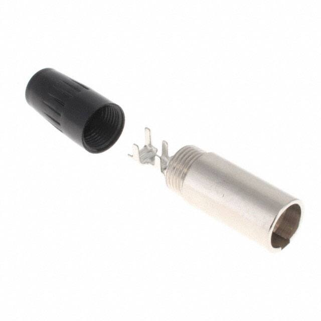


 工商网监
湘ICP备2023018690号
工商网监
湘ICP备2023018690号
