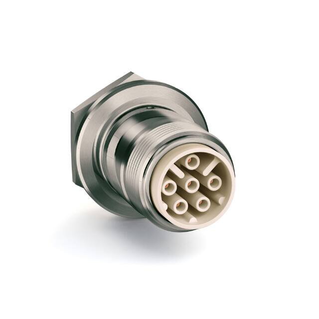
MOD Series
M Series
MC Series MCS Series
VP Series
100 Series
S Series
Series
Operating voltage up to 5 kVDC
Operating current up to 4,5 A
2 - 6 high voltage contacts
Quick and easy assembling
Protection class IP68 acc. DIN EN 60529
�General characteristics and
technical data Series MCS
Series
Housing
Locking system
threaded coupling
Panel mount type
round flange
Housing material
brass (CuZn)
Surface plating
nickel (Ni)
Protection class acc. DIN EN 60529 (mated connector)
IP68
Operating temperature
-30°C to +80°C
MCS Series
Contacts 0.7 mm
Termination method
solder / crimp
Rated current
4.5 A
Contact resistance
< 0,7 mΩ
Contact diameter
0.7 mm [.028"]
Wire size
AWG 26 - 22 (0.15-0.38 mm²)
Contact material
brass (CuZn)
Contact plating
gold (Au)
Mating cycles
≥ 5000
Insulation inserts
Number of contacts
2, 4, 6
Insulation material
PBT
Flammability class
UL94 V-0
Operating temperature
-40°C to +150°C
CTI value
600
Insulation material group
I (DIN IEC 60664)
Max. diameter of dielectric cable insulation
1.6 mm
Configurations
Type
205
405
Receptacle
Plug
Suitable cable dimensions (single wire)
max. Ø 1.6 mm [.063"]
AWG 26 - 22
72
© GES Electronic & Service GmbH
www.ges-electronic.de
605
�Type MCS605
Series
Electrical Values
6-pole 5 kVDC
Characteristics
Operating Voltage (DC)
5 kV
Number of pins
6
Test Voltage (DC)
8 kV
Insulation material
PBT
Rated Current
4.5 A
Type / Version / Description
Picture / Drawing
GB-MCS605
Receptacle, panel mount
incl. female contacts 0.7 mm
GS-MCS605
MCS Series
plug, panel mount
incl. male contacts 0.7 mm
KS-MCS605
plug, cable mount
incl. male contacts 0.7 mm
KB-MCS605
Receptacle, cable mount
incl. female contacts 0.7 mm
drawing - dimensions in mm [inch]
Plug
Receptacle
Cable mount
Description
5001600
GB-MCS605
5001605
GS-MCS605
5001610
KS-MCS605 6.5 – 4.0
6.5 – 4.0 [.256" - .157"]
5001611
KS-MCS605 8.0 – 5.0
8.0 – 5.0 [.315" - .197"]
5001612
KS-MCS605 9.5 – 6.5
9.5 – 6.5 [.374" - .256"]
5001613
KS-MCS605 10.5 – 7.0
10.5 – 7.0 [.413" - .276"]
Panel mount
Clamping range
(in mm [inch])
Screwed cable gland
Part no.
5001620
KB-MCS605 6.5 – 4.0
6.5 – 4.0 [.256" - .157"]
5001621
KB-MCS605 8.0 – 5.0
8.0 – 5.0 [.315" - .197”]
5001622
KB-MCS605 9.5 – 6.5
9.5 – 6.5 [.374" - .256"]
5001623
KB-MCS605 10.5 – 7.0
10.5 – 7.0 [.413" - .276"]
Accessories - page 76
6-core cable - page 80
© GES Electronic & Service GmbH
www.ges-electronic.de
75
�Assembly instructions (GB/GS)
Series
1.
6.
Part as delivered
contacts (1), insulation part (2), housing (3)
2.
Remove dielectric insulation of single wires
(L3 = 4 mm [.157"])
! Do not damage conductor.
7.
Panel cut out
D1 mm [inch]
L1 mm [inch]
22.20 [.874"]
10.10 [.398"]
8.
MCS Series
3.
Crimp or solder one contact (1) each on every conductor
! Tin-solder must not remain on contact surface!
Carefully remove cable jacket
(L2 = min. 30 mm [1.181"])
! Do not damage metal shield.
4.
Slide contacts (1) completely into insulation
part (2) until contacts snap
...
Put in all contacts at the same time
9.
Fold back shield
Put insulation part (2) into housing (3)
... Pay attention to notches.
5.
10.
Remove any filling elements from cable
© GES Electronic & Service GmbH
Assembly finished
www.ges-electronic.de
77
�Assembly instructions (KB/KS)
1.
6.
Part as delivered
cap (1), clamping rubber (2), outer cone (3), inner
cone (4), contacts (5), insulation part (6), housing (7)
2.
Place inner cone (4) on cable
7.
MCS Series
Place cap (1), clamping rubber (2) and outer
cone (3) on cable
! Respect correct order of parts (see picture).
3.
Remove dielectric insulation of single wires
(L2 = 4 mm [.157"])
! Do not damage conductor.
8.
Carefully remove cable jacket
(L1 = 28 mm [1.102"])
! �Do not damage metal shield.
Do not damage dielectric insulation.
4.
Crimp or solder one contact (5) each on every conductor
! Tin-solder must not remain on contact surface!
9.
Fold back shield braid over jacket
5.
Completely widen shield braid. Push outer cone (3)
and clamping rubber (2) under shield braid against
inner cone (4) until shield braid clamps between outer
cone (3) and inner cone (4)
10.
Remove any filling elements from cable
78
Series
© GES Electronic & Service GmbH
Cut overlapping shield braid
! C
� arefully remove loose shield parts. Loose shield
parts can cause electrical break down.
www.ges-electronic.de
�Assembly instructions (KB/KS)
Series
11.
13.
Slide contacts (5) completely into insulation
part (6) until contacts snap
... I�nsert all contacts at the same time. Pull gently
to check that contacts are correctly located
and remain in position.
Wrench size
cap
Wrench size
housing
Tightening
torque [Nm]
20
19
5
14.
Assembly finished
Slide insulation part (6) into housing (7)
until insulation part snap in
! U
� se notches for correct position of
insulation part.
MCS Series
12.
Put on cap
!
Note – important!
1. �Please carefully read assembly
instructions before cable assembly.
2. �Cable assembly must only be done
by trained and qualified personnel.
© GES Electronic & Service GmbH
www.ges-electronic.de
79
�
很抱歉,暂时无法提供与“5001600”相匹配的价格&库存,您可以联系我们找货
免费人工找货