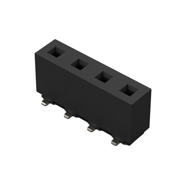
H
B±0.35
A±0.30
1.40
5.08±0.15
1.40
5.08
3.70
8.10
3.70
8.10
5.08
G
5.08
Ø1.80
Number of
Contacts
Pin 1.14X0.40
Recommended PCB Layout
Bottom Entry General Tolerance ±0.05
F
Recommended PCB Layout
Top Entry General Tolerance ±0.05
6.10
Cap
9.35±0.25
E
8.90
7.10
3.00
A
Solder Area
2.80 ref
Solder Area
0.12
Dimensions
A
B
2
5.08
10.16
3
10.16
15.24
4
15.24
20.32
5
20.32
25.40
6
25.40
30.48
7
30.48
35.56
8
35.56
40.64
9
40.64
45.72
10
45.72
50.80
11
50.80
55.88
12
55.88
60.96
13
60.96
66.04
14
66.04
71.12
15
71.12
76.20
7.10±0.30
A
D
Section A-A
Ordering Grid
Specifications
C
B
Material
Insulator: LCP, UL94V-0
Contact: Phosphor Bronze
BK015
Mechanical & Environmental
Operating Temperature: -40°C to +105°C
Soldering Process
IR Reflow: 260°C for 10 sec.
Manual Solder: 350°C for 3-5 sec
Plating
Contact: Tin All Over
Underplating: Nickel all over
Electrical
Current Rating: 7.9 Amp Per Pin
Contact Resistance: 30 mΩ max.
Insulation Resistance: 1500 MΩ min.
Dielectric Withstand Voltage: 1500 V AC
A
Mates with
(Subject to Pin Length)
BK010
BK020
For bottom entry applications, stringent soldering
control & pin alignment are required as lead to pad
misalignment could cause incorrect mating.
3
X
Request Samples
and Quotation
Packing Options
E = Tube with Cap (Standard)
B = Tape and Reel with Cap
D = Tube
Contact Plating
C= Tin All Over
Part Number
Product Description
BK015
5.08mm Pitch Socket, Single Row,
Surface Mount, Vertical,Dual Entry
Drawing Date
26th May 2017
By
2
C
No. of Contacts
02 to 15
Detail
1
XX
4
Revision
Date
5
CC
Tolerances (Except as Noted)
Drawing
Release
A1
09/09/21
X. ± 0.30
X.° ± 5°
X.X° ± 3°
X.X ± 0.25
X.XX ± 0.15 X.XX° ± 2°
X.XXX ± 0.10 X.XXX° ± 1°
Length
Angle
6
Units:
Metric (mm)
C
3rd Angle Projection
7
This drawing is confidential and
copyright of Global Connector
Technology, Ltd (GCT).
This drawing must not be copied
or disclosed without written
consent. E & OE
www.gct.co
Not to
Scale
Drawn By
CC
8
Sheet No.
1/1
很抱歉,暂时无法提供与“BK015-08-C-E”相匹配的价格&库存,您可以联系我们找货
免费人工找货