UTL SERIES
UL/IEC Power + Control Supply
��Overview
UTL Series |
Typical applications............................................ 06
Features & Benefits ........................................... 07
Range overview ................................................. 08
General technical characteristics ....................... 10
Stripping instructions for crimp contacts ........... 46
Tooling for crimp contacts ................................. 50
Handle & interchangeable heads
for crimp contacts .............................................. 52
Crimping control for crimp contacts .................. 53
Insertion tool & extraction tool
for crimp contacts .............................................. 54
Stripping instructions and tooling
for coax contacts ............................................... 55
Assembly instructions ........................................ 60
Mated connector length..................................... 65
Evaluation kit ..................................................... 67
Rated current & working voltage ....................... 71
UV resistance ..................................................... 72
UL94 + UL1977 .................................................. 73
IEC 61984 with IP code explained .................... 76
IEC 61140 explained ......................................... 77
What is NEMA Rating? ...................................... 79
Ethernet for the Layman .................................... 80
RS-485 for the Layman ...................................... 82
Customized solution &
Overmolded cable assembly.............................. 14
3 Contacts + ground ......................................... 18
5 Contacts ......................................................... 22
6 Contacts ......................................................... 26
8 Contacts ......................................................... 30
Contacts
Description ........................................................ 36
Contact plating selector guide .......................... 37
Contact selector guide ...................................... 38
Packaging .......................................................... 38
Crimp contacts .................................................. 39
#16 coaxial contacts .......................................... 41
PCB contacts ..................................................... 42
Appendices
Appendices
Connector
Contacts
Technical Information
Technical Information
Overview
Connector
Contents
Glossary of terms ............................................... 85
Part number index.............................................. 86
3
�UTL SERIES
© 2019 SOURIAU - SOURIAU is a registered trademark
�UTL Series
Overview
Typical applications ................................................................................................. 06
Features & Benefits ................................................................................................. 07
Range overview ...................................................................................................... 08
General technical characteristics ............................................................................. 10
5
�UTL Series | Overview
Energy - Power
Medical
© krungchingpixs / Fotolia
Telecom - Data infrastructure
Instrumentation & Measurement
6
© Volodymyr Kyrylyuk / Fotolia
Building Automation & Control
© smart.art / Fotolia
© Olivier Tuffé / Fotolia
Stage & Light
© Vibe Images / Fotolia
© Pavel Losevsky / Fotolia
Typical applications
�UTL Series | Overview
Features & Benefits
EASY
TO
USE
EASY
TO
SUPPLY
EASY
TO
CUSTOMIZE
High level of UL & IEC qualification
IP68/69K & UV Resistant
IK07 Impact Resistant
Moisture proof
Overview
EASY
TO
TRUST
•
•
•
•
• Push-pull coupling
• Blind mateable
• Sensitive tactile and audible click
• Worldwide distributor network
• Short lead-time
• Turnkey solution thanks to our overmold capabilities with
your cable spec
• Strong R&D team to develop customized solutions
UTL MAKES YOUR LIFE EASIER
7
�UTL Series | Overview
Range
PLUGS
UTL6JC 4 pos (103G1)
Protective shroud
Screwed backshell only available for UTL size 10:
connector layout 103G1
UTL5 4 pos (103G1)
HARNESS
Overmold
(straight or right angle)
Backshell UTLJC only for 4 pos (103G1) & 5 pos. (145)
“Clip” backshell only available for UTLM size 14:
connector layout 145
TYPES OF CONTACTS
UTL6
UTL6JC only for 4 pos (103G1) & 5 pos. (145)
Terminating Resistor
120Ω impedance
Only for 6 pos. (102G1W3) & 8 pos. (122G1W5)
Machined pin
Machined sealed pin
Stamped and formed pin
Machined socket
Machined sealed socket
Stamped and formed socket
Screw socket only for UTL145
8
EVALUATION KIT
�UTL Series | Overview
overview
RECEPTACLES
Overview
UTL1JC only for 4 pos (103G1)
In line - UTL1
HARNESS
Jam nut - UTL7
Overmold
(straight or right angle)
Square flange - UTL0 only for 4 pos. (103G1)
Terminating Resistor
120Ω impedance
Only for 6 pos. (102G1W3) & 8 pos. (122G1W5)
9
�UTL Series | Overview
Description
• The UTL Series is a plastic connector range
that meets industrial safety standards.
• UTL can be used for power supply and power
+ control supply with DMX or RDM signal.
• The «Key hole» of the coupling system
allows blind mating. In dark conditions the
mechanical
discriminations
allow
easy
mating to avoid connector damage.
• The stainless steel latch coupling system is
simple to use. With only 1 finger, connectors
are mated with an audible click.
• An optional protective shroud is also available to
prevent the disconnection of the connectors
without a tool.
• The UTL Series is rated at IP68/69K even in
dynamic conditions and remains sealed
even when used continuously underwater
or cleaned using a high pressure hose while
the cable is moving.
•
The UTL Series uses an outdoor rated
material per Underwriters Laboratories.
•
Cable assembly equipped with DMX +
Power cables suitable for outdoor use (PUR
or Neoprene outer jacket), please consult us
for more information.
Technical features
Materials
• Housing: Thermoplastic
- Raw material standards:
. UL94
. UL746
• Contacts: Copper alloy
• Latch: Stainless steel
Electrical
• Connector specially designed to be
engaged or disengaged in normal use when
live or under load
• First Mate Last Break contact mating on
ground line
• Signal lines (for UTL102G1W3 &
UTL122G1W5):
RS485 compliant, 2.5A 10V
• Finger touch proof (connector
equipped with socket contacts)
• In accordance with:
- Connector standards:
. UL 1977: UL file number ECBT2.E169916
. IEC 61984: please consult us
. C22.2 N°182.3: file number ECBT8.
E169916
- Equipment standards:
. IEC60065, IEC60598, IEC61076-2-103,
IEC60320
10
Environmental
• Temperature class (according to
IEC61984):
From -40°C to +105°C for connector
• Flammability rating:
UL 94: V-0 for connector
UL94: 5VA for thermoplastic
UL746C: 5 inch (127mm) end-product flame
test
• Salt spray:
≥1,000 hours
• UV resistant:
No mechanical degradation or important
color variation due to environmental
exposure (F1 material per the UL 746C)
• Sealing:
- IP68/69K mated with standard contacts
- IP68/69K unmated with specific contacts
- IP68 1 bar / 1 week
- IP67 mated for evaluation kits
- Moisture proof capability
• Fluid resistance:
- Gas and oil
- Mineral oil
- Acid bath
- Basic bath
- For other fluids, please consult us
• Halogen free
• RoHS compliant
Mechanical
COMPLIANT
• Durability:
- 250 mating in CBC (Current Breaking
Capacity) use (UL1977; IEC61984)
- 500 mating in COC use (IEC61984)
- 1,000 matings & unmatings tested
• Coupling system:
- Sensitive and audible click
- Blind mating
• Touchproof:
IP2X in unmated condition (connector
equipped with socket contacts)
• Shock:
IK07 according to IEC62262
�UTL Series | Overview
Qualification time saving
In today’s fast paced environment we are all buying electronic devices with confidence. To achieve such a high level of
trust, the regulator had to put in place a wide variety of safety standards. Some are dedicated to the equipment, some to
the connection.
SOURIAU designed and qualified the UTL Series according to the UL 1977 and IEC 61984 but we also took into
account additional requirements.
+
Additional Capabilities
❏
❏
❏
❏
❏
❏
❏
❏
Overview
UL 1977 & IEC 61 984 Qualified
Impact resistance
Stress relief
Flame retardant
Finger probe
Aging
Hot wire
Bending
Current breaking
In this way, the UTL Series is also compliant with ALL equipment standards mentioned below.
=
Easy Equipment Qualification
Now, the qualification of your equipment is much easier.
UL201
Safety standard of industrial equipment
UL 1995
Heating and cooling equipment
UL 2238
Cable assemblies and fittings for industrial
control and signal distribution
IEC 60601
Medical equipment
IEC 61010
Safety requirements for electrical equipment
for measurement, control, and laboratory use
IEC 60598
Street lights
UL/IEC 60950
Information technology equipment
11
�UTL SERIES
© 2019 SOURIAU - SOURIAU is a registered trademark
�UTL Series
Connector
Customized solution & overmolded cable assembly ....................................... 14
3 Contacts + ground
103G1: 16A 500V.................................................................... 18
5 Contacts
145: 16A 500V........................................................ 22
6 Contacts
102G1W3: 16A 500V.................................................................... 24
8 Contacts
122G1W5: 16A 500V.................................................................... 30
13
�UTL Series | Connector
SOURIAU has been designing harsh environment connectors for
over one century, year after year developing customized solutions
based on dedicated technical specifications from our customers.
Thanks to a strong R&T and R&D department and a certified
laboratory, we're able to propose customized solutions; the only
limit is your imagination!
© ESB Professional / Shutterstock
Customized solution capability
Overmolded cable assembly
SOURIAU has provided connectors for various applications for more than 90 years that have been used in the most extreme environments.
Conscious about the difficulty in finding a quick and reliable harness manufacturer, we began our own in-house overmolded cable assembly
production. It allows customers to reduce the number of suppliers and to take advantage of the “best in class” quality of the SOURIAU
group. Overmolding is a process that further enhances the sealing properties and helps to minimize stress on the cable termination to the
connector. In addition, the wires are encapsulated inside the molding which creates a barrier preventing liquid/moisture from entering the
equipment through the connector or cable jacket if breached.
14
�UTL Series | Connector
UTL overmolded cable assembly
Overmolding description
O-ring
Compound
Connector
Cable outer
sheath
PVC or PUR
overmolding
Connector with cable gland backshell
If cable jacket is breached...
GOOD
...water ingress unhampered, leading to damage.
Overmolded connector
If cable jacket is breached...
BEST
...prevents water ingress via capillary action.
Overmold design for illustration purpose only
15
�UTL Series | Connector
UTL overmolded cable assembly
Description
Cable - 3 + ground
• Outer sheath: rubber compound EM2
in acc. to HD 22.1 that is VDE 0282 part 1
• Outer sheath color: black
• Flame retardant in acc. to IEC 60332-1-2
resp. VDE 0482 part 332-1-2
• Resistant to Oil, Solvents, Water, Ozone,
aging and abrasion
Cable - 6 pos.
• Signal: 1 x 2 x 0.22 + shielding
Power: 3G1.5
• Outer sheath: PUR RAL9005
• Outer sheath color: black
• Core section: 0.22 mm² and 1.5 mm²
Cable - 8 pos.
• Signal: 2 x 2 x 0.22 + shielding
Power: 3G1.5
• Outer sheath: PUR RAL9005
• Outer sheath color: black
• Core section: 0.22 mm² and 1.5 mm²
Specifications
PLATING
SALT SPRAY
TEMPERATURE
Up to + 90° C (1) with 103G1 (4 pos)
No plating
≥1000 H
Up to + 80° C (1) with 102G1W3 (6 pos)
Up to + 80° C
(1) See page 17 for more information
16
(1)
with 122G1W5 (8 pos)
WATERPROOF
COUPLING
IP68/69K dynamic
mated & unmated
1,000 matings/unmatings
�UTL Series | Connector
UTL overmolded cable assembly
Cable information
Rated voltage:
U0/U: 450/750 V
Wire section:
3 + ground: 2.5 mm²
6 pos. & 8 pos.: 1.5 mm² (power), 0.22 mm² (signal)
Temperature:
3 + ground: flexible use and fixed installation -25° C up to +60° C
6 pos. & 8 pos.: flexible use -15° C up to +70° C, fixed installation -30° C up to +70° C
Harmonized reference:
3 + ground: H07 RNF 4G x 2.5
6 pos. & 8 pos.: Not Applicable
Nomenclature Key
Definitions of Cable Types
S:
Service Grade (also means extra hard service when not
followed by J, V, or P)
J:
Hard Service
V:
Vacuum cleaner cord (also light duty cable)
P:
Parallel cord (also known as zip cord) – Always light duty
E:
Thermoplastic Elastomer (UL/NEC designation ONLY)
O:
Oil Resistant outer jacket
OO: Oil Resistant outer jacket and insulation
T: Thermoplastic
W:
Outdoor-includes sunlight resistant jacket and wet location
rated conductors (formerly "W-A")
H:
Heater cable
VW-1: Flame retardant (vertical grade)
FT2: Flame retardant (horizontal grade)
SVT:
Thermoplastic insulated vacuum cleaner cord, with or
without 3rd conductor for grounding purposes;
300V (PVC)
SJT:
Junior hard service, thermoplastic insulated conductors
and jacket. 300V (PVC)
SJTW: Same as SJT except outdoor rated. (PVC)
SJTO: Same as SJT but oil resistant outer jacket. (PVC)
SJTOW: Same as SJTO except outdoor rated. (PVC)
ST:
Hard service cord with all thermoplastic construction,
600V (PVC)
STW: Same as ST except outdoor rated. (PVC)
STO: Same as ST but with oil resistant outer jacket. (PVC)
STOW: Same as STO except outdoor rated. (PVC)
Connector
Standardization of American Cable
17
�UTL Series | Connector
103G1 (shell size 10, 3 + ground, 4x#16)
Layout
OR
OR
OR
OR
OR
OR
OR
WITH
OR
Connector part number
Plugs and receptacles have to be equipped with both contact genders. Ground lines will never be equipped with the
same contacts as the neutral and phase.
Part number
Male insert
Female insert
Black color
Grey color
Black color
Grey color
Contact type
Connector type
Crimp or PCB
contacts
supplied separately
see page 21
Square flange receptacle
Jam nut receptacle
In line receptacle without backshell
In line receptacle with backshell
Plug for panel mounting
Plug for overmolding
Plug threaded without backshell and O-ring
Plug with backshell
UTL0103G1P
UTL7103G1P
UTL1103G1P
UTL1JC103G1P
UTL5103G1P
UTL6103G1P
UTL6TH103G1P
UTL6JC103G1P
UTL0103G1P03
UTL7103G1P03
UTL1103G1P03
UTL6103G1P03
-
UTL0103G1S
UTL7103G1S
UTL1103G1S
UTL1JC103G1S
UTL5103G1S
UTL6103G1S
UTL6TH103G1S
UTL6JC103G1S
UTL0103G1S03
UTL7103G1S03
UTL1103G1S03
UTL6103G1S03
-
Strandard delivered packaging: individual bag. For bulk delivery of 100 pcs please add a "B" after the P or S (connector gender) and before the potential "03" digits.
Overmolded cable assembly part number
Nbr
contacts
Size
Wire size
Description
Length* (FT)
Part number
4
4
4
4
4
4
4
4
4
4
4
4
10
10
10
10
10
10
10
10
10
10
10
10
14 AWG
16 AWG
18 AWG
14 AWG
16 AWG
18 AWG
14 AWG
16 AWG
18 AWG
14 AWG
16 AWG
18 AWG
D/E assembly 1 male plug & 1 female plug
D/E assembly 1 male plug & 1 female plug
D/E assembly 1 male plug & 1 female plug
S/E assembly 1 female plug
S/E assembly 1 female plug
S/E assembly 1 female plug
S/E assembly 1 male plug
S/E assembly 1 male plug
S/E assembly 1 male plug
D/E assembly 1 male plug & 1 female in line receptacle
D/E assembly 1 male plug & 1 female in line receptacle
D/E assembly 1 male plug & 1 female in line receptacle
3
3
3
3
3
3
3
3
3
3
3
3
UTLMKT63G1PS3FT
UTLMK63G1PS03FT00
UTLMK63G1PS03FT01
UTLMKT63G1S3FT
UTLMK63G1S03FT00
UTLMK63G1S03FT01
UTLMKT63G1P3FT
UTLMK63G1P03FT00
UTLMK63G1P03FT01
UTLMKT613G1SP3FT
UTLMK613G1PS03FT00
UTLMK613G1PS03FT01
* Other lengths available: 6 and 12 foot only: e.g. UTLMKT63G1PS6FT for a 6 foot version 14 AWG jumper or UTLMK63G1PS06FT01 for a 6 foot version 18 AWG jumper.
Contact us for custom length or design needs.
Evaluation kit
Evaluation kit is composed of 1 connector, contacts and 1 heat shrink boot for a quick and easy assembly production.
For more information please see page 67.
18
�3 + ground
16A/250-500V
UTL Series | Connector
per IEC 61984
103G1 (shell size 10, 3 + ground, 4x#16)
Dimensions (for mated connector lengths see page 65)
Square flange receptacle - UTL0
0.472"
1.181"
In line receptacle - UTL1 & Jam nut receptacle - UTL7
1.181"
1.322"
0.787"
Ø 3.2
1.125"
1.125"
Ø 0.708"
UTL1
UTL7
Front view
Plug - UTL5 & UTL6TH
1.456"
0.492"
Front view
Plug for overmolding - UTL6
0.610"
1.047"
0.444"
0.610"
Front view
UTL6TH
Plug with backshell - UTL6JC
1.051"
2.901" maxi
0.610"
1.027"
0.787"
1.137"
2.448"
Cable diameter acceptance of backshell: from
0.275" to 0.475"
Connector
Front view
In line receptacle - UTL1JC
1.181"
0.933"
1.027"
Ø 0.610"
UTL5
Cable diameter acceptance of backshell: from
0.275" to 0.475"
Front view
Front view
Panel cut out
Ø 0.874"
Ø 0.874"
0.370"
7"
67
0.858"
0.
7"
"
0
72
67
0.
0.
0.057"
Jam nut receptacle - UTL7
maximum panel thickness: 0.196"
Ø
Ø
Ø
1.055"
0.647"
Plug for panel mounting - UTL5
maximum panel thickness: 0.236"
Ø 0.129"
0.647"
Square flange receptacle - UTL0
0.057"
Note: all dimensions are in inch and for information only
19
�UTL Series | Connector
103G1 (shell size 10, 3 + ground, 4x#16)
Accessories and tooling
Dustcap for plug
IP67
Dustcap for receptacle
Handle (without head)
Tool kit
IP67
Part number
Part number
Part number
Part number
UTL610DCG
UTL10DCG
SHANDLES
TOOLKIT
Dustcap for male
receptacle
Dustcap for female
receptacle
IP68/69K
Head crimp tooling (without handle)
Contacts
IP68/69K
Part number
Part number
UTL103G1PDCG68
UTL103G1SDCG68
Extraction tool #16
Insertion tool #16
Part number
Part number
RX2025GE1
RTM205
Cable gland
backshell*
Backshell housing*
Part number
of head
Contact size
RM/RC 28M1K(1)
RM/RC 24M9K(1)
RM/RC 20M13K(1)
RM/RC 20M12K(1)
RM/RC 16M23K(1)
RM/RC 14M30K(1)
SM/SC 24ML1TK6(1)
SM/SC 20ML1TK6(1)
SM/SC 16ML1TK6(1)
SM/SC 14ML1TK6(1)
SM/SC 16ML11TK6(1)
RM/RC 16M25K
RM/RC 14M25K
RMDXK10D28K
RCDXK1D28K
RM/RC DX60xxD28K
RM/RC DXK10D28 +
YORX090
RM/RC DX60xxD28
S16RCM20*
S16RCM20*
S16RCM20*
S16RCM20*
S16RCM16*
S16RCM14*
S16SCM20*
S16SCM20*
S16SCML1*
S16SCML1*
S16SCML11*
S16RCM1625*
S16RCM1425*
Standard contacts
#16
Ø 0.062"
Coaxial contacts
M20S-1J
#16
Ø 0.062"
(1): Example of plating, for other plating options see page 38
* Heads to be used with handle PN: SHANDLES
Part number
Part number
UTL10JC
UTL10JCP1
+
Handle
=
Head
Complete set
* Backshells delivered with UTL10SEAL for sealing with plug or receptacle
O-ring
Nut
Protective shroud
Part number
Part number
Part number
Part number
UTL610PS
SWSFILLERPLUG
UTL10SEAL
UTL10NUT
Can be used only with UTL5, UTL6JC, UTL6TH
20
Sealing plug
See instruction page 59
�3 + ground
16A/250-500V
UTL Series | Connector
per IEC 61984
103G1 (shell size 10, 3 + ground, 4x#16)
Contacts
Contact type
AWG
Crimp
Machined
Stamped & Formed reeled contacts
See note (2) for loose piece
Max
insulator Ø
0.021"
0.039"
26-24
RM24M9K
RC24M9K
0.031"
0.062"
22-20
RM20M13K(1)
RC20M13K(1)
0.045"
0.070"
22-20
RM20M12K
(1)
RC20M12K
0.045"
0.086"
20-16
RM16M23K(1)
RC16M23K(1)
0.070"
0.125"
16-14
RM14M30K
RC14M30K
(1)
(1)
(1)
(1)
(1)
RM16M25K
0.090"
0.125"
RC16M25K
0.070"
0.125"
16-14
RM14M25K
RC14M25K
0.089"
0.125"
24
RM24M25K(3)
RC24M25K(3)
0.025"
0.125"
26-24
SM24M1TK6(1)(2)
SC24M1TK6(1)(2)
-
0.035"- 0.062"
22-20
SM20M1TK6
(1)(2)
SC20M1TK6
-
0.047"- 0.082"
18-16
SM16M1TK6(1)(2)
SC16M1TK6(1)(2)
-
0.125"
SM16M11TK6
SC16M11TK6
-
0.118"
SM14M1TK6(1)(2)
SC14M1TK6(1)(2)
-
0.125"
RMDXK10D28
RCDXK1D28
-
-
Cable multipiece
Coaxial*
Max
wire Ø
RC28M1K(1)
14
Cable monocrimp
see page 41
Twisted pair monocrimp
PCB
Female
RM28M1K(1)
18-16
Twisted pair multipiece
Male
30-28
20-16
Machined sealed
(with O-Ring for IP68/69K unmated)
Part number
(1)(2)
(1)(2)
(1)(2)
RMDX60xxD28
RCDX60xxD28
-
-
RMDXK10D28 +
YORX090
RCDXK1D28 +
YORX090
-
-
RMDX60xxD28
RCDX60xxD28
-
-
For male insert
-
RM20M12E8K
RC20M12E84K
-
For female insert
-
RM20M12E8K
RC20M12E83K
-
Connector
#16
-
(1): Example of plating, for other plating options see page 38 / (2): For loose piece contact packaging, place "L" in part number. Example: SM20ML1TK6
(3): Includes RM/RC24M25K contacts + a ferrule RR24M1K. The ferrule can also be ordered separately. See page 53
*: Coax contacts cannot be used in the ground cavity
Note: all dimensions are in inch
REMINDER
Plugs and receptacles have to be equipped with both contact genders.
EX: UTL6103G1P = 3 x SM16M1TK6 (signal) + 1 x SC16M1TK6 (ground)
UTS 103 derating curves
Electrical characteristics
Current (A)
30
UL
16A 600V V0
13A 277V for CBC use
CN
13A 600V
10A 277V for CBC use
28
25
23
Test
conditions
20
18
15
Contact used:
Machined contacts
Wires used:
1.31mm²
IEC
16A 500V 6KV 4
13A 250V 4KV 4 for CBC use
13
10
8
5
3
0
Current use
0
20
40
60
80
Ambient operating temperature (°C)
Limited use
100
120
Not recommended use
Derating curves based on a continuous current, for information only, please contact us for
specific need.
21
�UTL Series | Connector
145 (shell size 14, 5x#16)
OR
OR
Layout
WITH
Connector part number
Contact type
Connector type
Crimp contacts
to be ordered
separately see page 25
Screw termination
contacts, delivered
with connector (1)
Part number
Male insert
Female insert
Plug with backshell*
-
UTL6JC145S
Plug without backshell
-
UTL6145S
Jam-nut without backshell
UTL7145P
-
Plug with backshell*
-
UTL6JC145SSCR
Plug without backshell
-
UTL6145SSCR
* Non removable backshell when mated. IP68/69K not guaranted if backshell removed.
1: Screw termination version (from AWG18 to AWG14) or crimp version.
Strandard delivered packaging: individual bag. For bulk delivery of 100 pcs please add a "B" after the P or S (connector gender) and before the potential "03" digits.
Overmolded cable assembly
Please consult us.
22
�5 contacts
16A/250-500V
UTL Series | Connector
per IEC 61984
145 (shell size 14, 5x#16)
Dimensions (for mated connector lengths see page 66)
Jam nut receptacle - UTL7
1.354"
1.417"
0.562"
1.472"
1.240"
Connector
Front view
Plug with backshell - UTL6
0.594"
1.228"
2.748"
Ø 0.393" mini
Ø 0.669" maxi
3.976"
Front view
Panel cut out
Plug without backshell - UTL6
Jam nut receptacle - UTL7
1.925"
Ø 1.181"
Ø
0"
00
1.
0.940"
Maximun panel thickness: 0.196"
0.594"
1.228"
0.814"
0.059"
Front view
Note: all dimensions are in inch and for information only
23
�UTL Series | Connector
145 (shell size 14, 5x#16)
Tooling
Handle (without head)
Tool kit
Head crimp tooling (without handle)
Contacts
Part number
Part number
SHANDLES
TOOLKIT
+
Handle
=
Head
Complete set
Extraction tool #16
Insertion tool #16
Part number
Part number
RX2025GE1
RTM205
Accessories
24
Backshell
Backshell
Part number
Part number
UTL14JC
UTL14JCP1
RM/RC 28M1K(1)
RM/RC 24M9K(1)
RM/RC 20M13K(1)
RM/RC 20M12K(1)
RM/RC 16M23K(1)
RM/RC 14M30K(1)
SM/SC 24ML1TK6(1)
SM/SC 20ML1TK6(1)
SM/SC 16ML1TK6(1)
SM/SC 14ML1TK6(1)
SM/SC 16ML11TK6(1)
Contact size
Standard contacts
#16
Ø 0.062"
(1): Example of plating, for other plating options see page 38
* Heads to be used with handle PN: SHANDLES
Part number
of head
S16RCM20*
S16RCM20*
S16RCM20*
S16RCM20*
S16RCM16*
S16RCM14*
S16SCM20*
S16SCM20*
S16SCML1*
S16SCML1*
S16SCML11*
�5 contacts
16A/250-500V
UTL Series | Connector
per IEC 61984
145 (shell size 14, 5x#16)
Contacts
Contact type
AWG
Crimp
Machined
Stamped & Formed reeled contacts
See note (2) for loose piece
Max
insulator Ø
0.021"
0.039"
26-24
RM24M9K
RC24M9K
0.031"
0.062"
22-20
RM20M13K(1)
RC20M13K(1)
0.045"
0.070"
22-20
RM20M12K
(1)
RC20M12K
0.045"
0.086"
20-16
RM16M23K(1)
RC16M23K(1)
0.070"
0.125"
16-14
RM14M30K
RC14M30K
(1)
(1)
(1)
(1)
(1)
RM16M25K
0.090"
0.125"
RC16M25K
0.070"
0.125"
16-14
RM14M25K
RC14M25K
0.089"
0.125"
24
RM24M25K(3)
RC24M25K(3)
0.025"
0.125"
26-24
SM24M1TK6(1)(2)
SC24M1TK6(1)(2)
-
0.035"- 0.062"
22-20
SM20M1TK6
(1)(2)
SC20M1TK6
-
0.047"- 0.082"
18-16
SM16M1TK6(1)(2)
SC16M1TK6(1)(2)
-
0.125"
SM16M11TK6
SC16M11TK6
-
0.118"
SM14M1TK6(1)(2)
SC14M1TK6(1)(2)
-
0.125"
RMDXK10D28
RCDXK1D28
-
-
Cable multipiece
Coaxial*
Max
wire Ø
RC28M1K(1)
14
Cable monocrimp
see page 41
Twisted pair monocrimp
Female
RM28M1K(1)
18-16
Twisted pair multipiece
Male
30-28
20-16
Machined sealed
(with O-Ring for IP68/69K unmated)
Part number
(1)(2)
(1)(2)
(1)(2)
RMDX60xxD28
RCDX60xxD28
-
-
RMDXK10D28 +
YORX090
RCDXK1D28 +
YORX090
-
-
RMDX60xxD28
RCDX60xxD28
-
Connector
#16
-
(1): Example of plating, for other plating options see page 38
(2): For loose piece contact packaging, place "L" in part number. Example: SM20ML1TK6
(3): Includes RM/RC24M25K contacts + a ferrule RR24M1K. The ferrule can also be ordered separately. See page 53
*: Coax contacts cannot be used in the ground cavity
Note: all dimensions are in inch
Electrical characteristics
UTL145 derating curves
Current (A)
30
UL
16A 600V V0
13A 277V for CBC use
CN
13A 600V
10A 277V for CBC use
Test
conditions
28
25
23
Contact used:
Machined contacts
Wires used:
#16 contacts wired
onto 1.5mm² or
AWG16 conductors
20
18
15
13
10
8
5
IEC
16A 500V 4KV 4
13A 250V 2.5KV 4 for CBC use
3
0
0
Theoretic current use
20
40
60
80
Ambient operating temperature (°C)
Limited use
100
120
Not recommended use
Derating curves based on a continuous current, for information only, please contact us for
specific need.
25
�UTL Series | Connector
102G1W3 (shell size 10, 3x#16 + 3x#20)
OR
OR
Layout
WITH
Connector part number
Plugs and receptacles have to be equipped with both contact genders. Ground lines will never be equipped with the
same contacts as the neutral and phase.
Part number
Contact type
Connector type
Female insert
Black color
Black color
Plug
UTL6102G1W3P
UTL6102G1W3S
Jam nut receptacle
UTL7102G1W3P
UTL7102G1W3S
In line receptacle
UTL1102G1W3P
UTL1102G1W3S
Terminating Resistor
plug - 120Ω
UTL6102G1W3PCDMX
UTL6102G1W3SCDMX
Terminating Resistor
receptacle - 120Ω
UTL1102G1W3PCDMX
UTL1102G1W3SCDMX
Crimp contacts
supplied
separately see page 29
Contacts included
Male insert
The Terminating Resistor is only designed to ensure the 120 Ohms impedance on the signal lines, no contact loaded in the power positions.
#20 contacts and plastic plate are not removable.
Strandard delivered packaging: individual bag. For bulk delivery of 100 pcs please add a "B" after the P or S (connector gender) and before the potential "03" digits.
Overmolded cable assembly part number
Layout
Wire size
14 AWG
102G1W3
16 AWG
Overmolded harnesses, straight ending
Connector
Length*
(FT )
Part number
D/E assembly 1 male plug & 1 female plug
3
UTL6V2G1W3PS03FT0
S/E assembly 1 female plug
3
UTL6V2G1W3S03FT0
S/E assembly 1 male plug
3
UTL6V2G1W3P03FT0
D/E assembly 1 male plug & 1 female in line receptacle
3
UTL61V2G1W3PS03FT0
D/E assembly 1 male plug & 1 female plug
3
UTL6V2G1W3PS03FT1
S/E assembly 1 female plug
3
UTL6V2G1W3S03FT1
S/E assembly 1 male plug
3
UTL6V2G1W3P03FT1
D/E assembly 1 male plug & 1 female in line receptacle
3
UTL61V2G1W3PS03FT1
* Other stock lengths available: 6 and 12 foot only: e.g. UTL6V2G1W3P06FT0 for a 6 foot version 14 AWG
Contact us for custom length or design needs.
Evaluation kit
Evaluation kit is composed of 1 connector, contacts and 1 heat shrink boot for a quick and easy assembly production.
For more information please see page 68.
26
�6 contacts
16A/500V
UTL Series | Connector
per IEC 61984
102G1W3 (shell size 10, 3x#16 + 3x#20)
Dimensions (for mated connector lengths see page 65)
Plug for overmolding - UTL6
0.787"
1.106"
0.444"
0.610"
Ø 0.610"
1.125"
Front view
Front view
Jam nut receptacle - UTL7
Terminating Resistor plug
0.787"
0.610"
0.944"
2.559" maxi
1.125"
0.551"
0.893"
1.240"
Connector
1.240"
0.944"
In line receptacle - UTL1
Front view
Front view
Panel cut out
Terminating Resistor receptacle
Jam nut receptacle - UTL7
Ø 0.874"
Ø
7"
67
0.
Front view
0.647"
Maximun panel thickness: 0.196"
0.787"
1.125"
2.559" maxi
0.057"
Note: all dimensions are in inch and for information only
27
�UTL Series | Connector
102G1W3 (shell size 10, 3x#16 + 3x#20)
Accessories and tooling
Dustcap for plug
IP67
Dustcap for receptacle
Handle (without head)
Tool kit
IP67
Part number
Part number
Part number
Part number
UTL610DCG
UTL10DCG
SHANDLES
TOOLKIT
Dustcap for male
receptacle
Dustcap for female
receptacle
IP68/69K
Head crimp tooling (without handle)
IP68/69K
Contacts
Part number
Part number
UTL102G1W3PDCG68
UTL102G1W3SDCG68
Extraction tool #16
Insertion tool #16
Part number
Part number
RX2025GE1
RTM205
Extraction tool #20
Part number
of head
Contact size
RM/RC 24W3K(1)
RM/RC 20W3K(1)
RM/RC 18W3K(1)
SM/SC 24WL3(1)(2)
SM/SC 20WL3(1)(2)
RM/RC 28M1K(1)
RM/RC 24M9K(1)
RM/RC 20M13K(1)
RM/RC 20M12K(1)
RM/RC 16M23K(1)
RM/RC 14M30K(1)
SM/SC 24ML1TK6(1)
SM/SC 20ML1TK6(1)
SM/SC 16ML1TK6(1)
SM/SC 14ML1TK6(1)
SM/SC 16ML11TK6(1)
RMDXK10D28K
RCDXK1D28K
RM/RC DX60xxD28K
RM/RC DXK10D28 +
YORX090
RM/RC DX60xxD28
S20RCM*
S20RCM*
S20RCM*
S20SCM20*
S20SCM20*
S16RCM20*
S16RCM20*
S16RCM20*
S16RCM20*
S16RCM16*
S16RCM14*
S16SCM20*
S16SCM20*
S16SCML1*
S16SCML1*
S16SCML11*
Standard contacts
#20
Ø 0.039"
Standard contacts
#16
Ø 0.062"
Coaxial contacts
M20S-1J
#16
Ø 0.062"
(1): Example of plating, for other plating options see page 38
* Heads to be used with handle PN: SHANDLES
Part number
RX20D44
28
+
Handle
(2): loose contact
=
Head
Complete set
�6 contacts
16A/500V
UTL Series | Connector
per IEC 61984
102G1W3 (shell size 10, 3x#16 + 3x#20)
Contacts
#20
Contact type
AWG
26-24
22-20
Machined
Crimp
20-18
26-24
26-24
Stamped & Formed reeled contacts
See note (2) for loose piece
22-20
22-20
Part number
Max
wire Ø
Max
insulator Ø
RC24W3K(1)
RC20W3K(1)
RC18W3K(1)
0.031"
0.062"
0.045"
0.062"
0.051"
0.082"
SM24W3TK6(1)(2)
SM24W3S26(1)(2)
SM20W3TK6(1)(2)
SM20W3S26(1)(2)
SC24W3TK6(1)(2)
SC24W3S25(1)(2)
SC20W3TK6(1)(2)
SC20W3S25(1)(2)
-
0.035"- 0.062"
-
0.035"- 0.062"
-
0.047"- 0.082"
-
0.047"- 0.082"
RM28M1K(1)
RM24M9K(1)
RM20M13K(1)
RM20M12K(1)
RM16M23K(1)
RM14M30K(1)
RC28M1K(1)
RC24M9K(1)
RC20M13K(1)
RC20M12K(1)
RC16M23K(1)
RC14M30K(1)
0.021"
0.039"
0.031"
0.062"
0.045"
0.070"
0.045"
0.086"
0.070"
0.125"
0.090"
0.125"
SM24M1TK6(1)(2)
SM20M1TK6(1)(2)
SM16M1TK6(1)(2)
SM16M11TK6(1)(2)
SM14M1TK6(1)(2)
SC24M1TK6(1)(2)
SC20M1TK6(1)(2)
SC16M1TK6(1)(2)
SC16M11TK6(1)(2)
SC14M1TK6(1)(2)
-
0.035"- 0.062"
-
0.047"- 0.082"
-
0.125"
-
0.118"
-
0.125"
RMDXK10D28
RMDX60xxD28
RMDXK10D28 +
YORX090
RMDX60xxD28
RCDXK1D28
RCDX60xxD28
RCDXK1D28 +
YORX090
RCDX60xxD28
-
-
-
-
-
-
Male
Female
RM24W3K(1)
RM20W3K(1)
RM18W3K(1)
30-28
26-24
22-20
Machined
22-20
Crimp
20-16
16-14
26-24
22-20
Stamped & Formed reeled contacts
18-16
See note (2) for loose piece
18-16
14
Coaxial*
Cable multipiece
Cable monocrimp
Twisted pair multipiece
see page 41
Twisted pair monocrimp
-
(1): Example of plating, for other plating options see page 38
(2): For loose piece contact packaging, place "L" in part number. Example: SM20ML1TK6
*: Coax contacts cannot be used in the ground cavity
Note: all dimensions are in inch
REMINDER
Plugs and receptacles have to be equipped with both contact genders.
EX: UTL6102W3G1P = 2 x SM16M1TK6 (power) + 1 x SC16M1TK6 (ground) + 3 x SM20W3TK6 (signal)
Electrical characteristics
UTL102G1W3 derating curves
Current (A) 30
UL
16A 600V V0
13A 277V for CBC use
CN
13A 600V
10A 277V for CBC use
IEC
16A 500V 6KV 4
13A 250V 4KV 4 for CBC use
Test
conditions
Contact used:
Machined contacts
Wires used:
#16 contacts wired
onto 1.5mm² or
16AWG conductors
#20 contacts wired
onto 0.5mm² or
20AWG conductors
and powered at
2.5 Amps
28
25
23
20
18
15
13
10
8
5
3
0
0
20
40
60
80
Ambient operating temperature (°C)
100
120
Theoretic current use
Limited use
Not recommended use
Derating curves based on a continuous current, for information only, please contact us for
specific need.
29
Connector
#16
�UTL Series | Connector
122G1W5 (shell size 12, 3x#16 + 5x#20)
OR
OR
Layout
WITH
Connector part number
Plugs and receptacles have to be equipped with both contact genders. Ground lines will never be equipped with the
same contacts as the neutral and phase.
Contact type
Part number
Connector type
Male insert with female ground
Female insert with male ground
Crimp contacts
supplied
separately see page 33
Plug
UTL6122G1W5P
UTL6122G1W5S
Jam nut receptacle
UTL7122G1W5P
UTL7122G1W5S
In line receptacle
UTL1122G1W5P
UTL1122G1W5S
UTL6122G1W5PCDMX
UTL6122G1W5SCDMX
Contacts included
Terminating Resistor plug
- 120Ω
Terminating Resistor
receptacle - 120Ω
UTL1122G1W5PCDMX
UTL1122G1W5SCDMX
The Terminating Resistor is only designed to ensure the 120 Ohms impedance on the signal lines, no contact loaded in the power positions.
#20 contacts and plastic plate are not removable.
Strandard delivered packaging: individual bag. For bulk delivery of 100 pcs please add a "B" after the P or S (connector gender) and before the potential "03" digits.
Overmolded cable assembly part number
Layout
Wire size
14 AWG
122G1W5
16 AWG
Overmolded harnesses, straight ending
Connector
Length*
(FT )
Part number
D/E assembly 1 male plug & 1 female plug
3
UTL6122G1W5PS03FT0
S/E assembly 1 female plug
3
UTL6122G1W5S03FT0
S/E assembly 1 male plug
3
UTL6122G1W5P03FT0
D/E assembly 1 male plug & 1 female in line receptacle
3
UTL6V122G1W5PS03F0
D/E assembly 1 male plug & 1 female plug
3
UTL6122G1W5PS03FT1
S/E assembly 1 female plug
3
UTL6122G1W5S03FT1
S/E assembly 1 male plug
3
UTL6122G1W5P03FT1
D/E assembly 1 male plug & 1 female in line receptacle
3
UTL6V122G1W5PS03F1
* Other stock lengths available: 6 and 12 foot only: e.g. UTL6V122G1W5PS06F0 for a 6 foot version 14 AWG
Contact us for custom length or design needs.
Evaluation kit
Evaluation kit is composed of 1 connector, contacts and 1 heat shrink boot for a quick and easy assembly production.
For more information please see page 69.
30
�8 contacts
16A/500V
UTL Series | Connector
per IEC 61984
122G1W5 (shell size 12, 3x#16 + 5x#20)
Dimensions (for mated connector lengths see page 66)
Plug for overmolding - UTL6
In line receptacle - UTL1
0.787"
0.551"
1.106"
0.444"
0.610"
1.043"
1.255"
1.240"
Ø 1.133"
Jam nut receptacle - UTL7
1.240"
0.551"
Connector
Front view
Front view
Terminating Resistor plug
0.787"
0.610"
1.043"
1.062"
1.255"
2.755" maxi
Ø28.8
Front view
Front view
Panel cut out
Terminating Resistor receptacle
Jam nut receptacle - UTL7
Ø 1.062"
Ø
5"
87
0.
Front view
0.826"
Maximun panel thickness: 0.196"
0.787"
1.255"
2.755" maxi
0.059"
Note: all dimensions are in inch and for information only
31
�UTL Series | Connector
122G1W5 (shell size 12, 3x#16 + 5x#20)
Accessories and tooling
Dustcap for plug
IP67
Dustcap for receptacle
Handle (without head)
Tool kit
IP67
Part number
Part number
Part number
Part number
UTL612DCG
UTL12DCG
SHANDLES
TOOLKIT
Extraction tool #16
Insertion tool #16
Head crimp tooling (without handle)
Contacts
Part number
Part number
RX2025GE1
RTM205
Part number
of head
Contact size
RM/RC 24W3K(1)
RM/RC 20W3K(1)
RM/RC 18W3K(1)
SM/SC 24WL3(1)(2)
SM/SC 20WL3(1)(2)
RM/RC 28M1K(1)
RM/RC 24M9K(1)
RM/RC 20M13K(1)
RM/RC 20M12K(1)
RM/RC 16M23K(1)
RM/RC 14M30K(1)
SM/SC 24ML1TK6(1)
SM/SC 20ML1TK6(1)
SM/SC 16ML1TK6(1)
SM/SC 14ML1TK6(1)
SM/SC 16ML11TK6(1)
RMDXK10D28K
RCDXK1D28K
RM/RC DX60xxD28K
RM/RC DXK10D28 +
YORX090
RM/RC DX60xxD28
S20RCM*
S20RCM*
S20RCM*
S20SCM20*
S20SCM20*
S16RCM20*
S16RCM20*
S16RCM20*
S16RCM20*
S16RCM16*
S16RCM14*
S16SCM20*
S16SCM20*
S16SCML1*
S16SCML1*
S16SCML11*
Standard contacts
#20
Ø 0.039"
Standard contacts
#16
Ø 0.062"
Coaxial contacts
M20S-1J
#16
Ø 0.062"
(1): Example of plating, for other plating options see page 38
* Heads to be used with handle PN: SHANDLES
+
Handle
32
(2): loose contact
=
Head
Complete set
�8 contacts
16A/500V
UTL Series | Connector
per IEC 61984
122G1W5 (shell size 12, 3x#16 + 5x#20)
Contacts
#20
Contact type
AWG
26-24
22-20
Machined
Crimp
20-18
26-24
26-24
Stamped & Formed reeled contacts
See note (2) for loose piece
22-20
22-20
Part number
Max
wire Ø
Max
insulator Ø
RC24W3K(1)
RC20W3K(1)
RC18W3K(1)
0.031"
0.062"
0.045"
0.062"
0.051"
0.082"
SM24W3TK6(1)(2)
SM24W3S26(1)(2)
SM20W3TK6(1)(2)
SM20W3S26(1)(2)
SC24W3TK6(1)(2)
SC24W3S25(1)(2)
SC20W3TK6(1)(2)
SC20W3S25(1)(2)
-
0.035"- 0.062"
-
0.035"- 0.062"
-
0.047"- 0.082"
-
0.047"- 0.082"
RM28M1K(1)
RM24M9K(1)
RM20M13K(1)
RM20M12K(1)
RM16M23K(1)
RM14M30K(1)
RC28M1K(1)
RC24M9K(1)
RC20M13K(1)
RC20M12K(1)
RC16M23K(1)
RC14M30K(1)
0.021"
0.039"
0.031"
0.062"
0.045"
0.070"
0.045"
0.086"
0.070"
0.125"
0.090"
0.125"
SM24M1TK6(1)(2)
SM20M1TK6(1)(2)
SM16M1TK6(1)(2)
SM16M11TK6(1)(2)
SM14M1TK6(1)(2)
SC24M1TK6(1)(2)
SC20M1TK6(1)(2)
SC16M1TK6(1)(2)
SC16M11TK6(1)(2)
SC14M1TK6(1)(2)
-
0.035"- 0.062"
-
0.047"- 0.082"
-
0.125"
-
0.118"
-
0.125"
RMDXK10D28
RMDX60xxD28
RMDXK10D28 +
YORX090
RMDX60xxD28
RCDXK1D28
RCDX60xxD28
RCDXK1D28 +
YORX090
RCDX60xxD28
-
-
-
-
-
-
Male
Female
RM24W3K(1)
RM20W3K(1)
RM18W3K(1)
30-28
26-24
22-20
Machined
22-20
Crimp
20-16
16-14
26-24
22-20
Stamped & Formed reeled contacts
18-16
See note (2) for loose piece
18-16
14
Coaxial
Cable multipiece
Cable monocrimp
Twisted pair multipiece
see page 41
Twisted pair monocrimp
-
(1): Example of plating, for other plating options see page 38
(2): For loose piece contact packaging, place "L" in part number. Example: SM20ML1TK6
*: Coax contacts cannot be used in the ground cavity
Note: all dimensions are in inch
REMINDER
Plugs and receptacles have to be equipped with both contact genders.
EX: UTL6122G1W5P = 2 x SM16M1TK6 (power) + 1 x SC16M1TK6 (ground) + 5 x SM20W3TK6 (signal)
Electrical characteristics
UTL122G1W5 derating curves
Current (A) 30
UL
16A 600V V0
13A 277V for CBC use
CN
13A 600V
10A 277V for CBC use
IEC
16A 500V 6KV 4
13A 250V 4KV 4 for CBC use
Test
conditions
Contact used:
Machined contacts
Wires used:
#16 contacts wired
onto 2.5mm² or
14AWG conductors
#20 contacts wired
onto 0.5mm² or
20AWG conductors
and powered at
2.5 Amps
28
25
23
20
18
15
13
10
8
5
3
0
0
20
40
60
80
Ambient operating temperature (°C)
100
120
Theoretic current use
Limited use
Not recommended use
Derating curves based on a continuous current, for information only, please contact us for
specific need.
33
Connector
#16
�UTL SERIES
© 2019 SOURIAU - SOURIAU is a registered trademark
�UTL Series
Contacts
Description ................................................................................................................ 36
Contact plating selector guide .................................................................................. 37
Contact selector guide .............................................................................................. 38
Packaging .................................................................................................................. 38
Crimp contacts .......................................................................................................... 39
#16 coaxial contacts .................................................................................................. 41
PCB contacts ............................................................................................................. 42
35
�UTL Series | Contacts
Contacts
Description
The UTL series is delivered without contacts (crimp version). This series offers the unique possibility to use the same contact in any layout as
long as it receives the same active part size.
This provides the benefit of standardization and subsequent reduced inventory costs. In addition, it eliminates the need for added tooling and
simplifies the assembly process. SOURIAU contacts are designed for simple snap-in installation and further eliminate the need for insertion
tooling.
Crimp contacts are available in different versions:
• Machined
• Stamped & Formed
The UTL series 3 + ground can be equipped with PCB contacts
36
• Coaxial
�UTL Series | Contacts
Contacts
Contact plating selector guide
Once the contact size has been selected, the next step is to decide on which type to use. SOURIAU offers two main types of electrical contacts:
• Machined
• Stamped & Formed
Machined contacts are generally chosen as a better solution for power applications or when lower quantities are needed.
Stamped & formed contacts offer the ability to be crimped automatically which makes them more suitable for high volume production
applications.
The next decision to make is: What plating should I choose?
The graph below can help guide you to plating recommendations based on application, mating cycles and current/voltage needs.
Note: do not mix different plating (i.e. tin plated pin contacts with gold plated socket contacts).
Number of
cycles
Vibration
250
100
0.4μm of gold
min
Contacts
Gold flash
Silver
Tin
Current /
Voltage
1Amp
5mV
Contact
size
#20
#12
#16
#8
37
�UTL Series | Contacts
Contacts
Plating selector guide
Contacts supplied separately
Electrical characteristics: contact resistance
#20
Ø 0.039"
#16
Ø 0.062"
Machined
< 6mΩ
Stamped and Formed
< 6mΩ
Machined
< 3mΩ
Stamped and Formed
< 6mΩ
Stamped & Formed contacts
Contact
size
#20
Ø 0.039"
#16
Ø 0.062"
Plating description
Plating
code
Active area
Other areas
S25
(female)
0,75μm Gold mini
over Nickel
Gold flash
over Nickel
S26
(male)
0,75μm Gold mini
over Nickel
Gold flash
over Nickel
TK6
0,5μm - 2,5μm Sn pre-plated
-
S31
Gold Flash over Nickel
S18
0,75μm Gold mini
over Nickel
Crimped area: 1.3µ Tin
mini over Nickel
Other areas: 1.3µ Tin
mini
D70
0,13μm Gold mini
over Nickel
Gold flash
over Nickel
TK6
0,5μm - 2,5μm Sn pre-plated
-
Machined contacts
Contact
size
Plating
code
Plating description
#20
Ø 0.039"
K
0.4 μm Gold over 2 μm Nickel mini
K
0.4 μm Gold over 2 μm Nickel mini
J
Gold Flash over Nickel 2 μm mini
#16
Ø 0.062"
Active area
T
Tin 3 μm (-0/+2) over 1.3 μm Nickel mini
D28*
0.75 μm mini Gold over 2 μm Nickel mini
* For Coax contacts only
Packaging - Size contacts #20 & #16
Due to the wide variety of applications, contact packaging is offered for small series (bulk package) and high volume production (reeled contacts):
Machined contacts*
Stamped & Formed
• 25 pieces loose package
• 3,000 pieces reeled
• 50 pieces bulk package
• 1,000 pieces bulk package
* Note : 1,000 pieces bulk package available by adding 1000 at the end of the part number: e.g. RC16M23K1000
2,000 pieces reeled package available by adding K at the begining of the part number: e.g. KRC16M23K
38
• 2,000 pieces reeled
Size #16 only
�UTL Series | Contacts
Crimp contacts
Standard version
Contact
size
#16
Ø 0.062"
Stamped & Formed
Wire size
Type
Machined
#20
Ø 0.039"
Machined
Part number
AWG
mm²
Male
26-24
0.13-0.20
RM24W3K
SM24W3-
(1)
Stamped &
Formed
26-24
0.13-0.25
Machined
22-20
0.32-0.52
Stamped &
Formed
22-20
0.35-0.5
SM24WL3-
-
RC18W3K
RC28M1RC24M9SC24M1-(1)
SC24ML1-(2)
RC20M13RC20M12SC20M1-(1)
SC20ML1-(2)
RC16M23-
0.051"
0.082" max
K
0.021"
0.043"
K, J
0.031"
0.062"
K, J
Stamped &
Formed
22-20
0.35-0.5
Machined
20-16
0.52-1.5
Machined
Sealed contact
20-16
0.52-1.5
RM16M25K
Machined
Sealed contact
24
0.25
16-14
1.5-2.5
Stamped &
Formed
14
2.0-2.5
Machined
Sealed contact
16-14
1.5-2.5
TK6
S25 (female)
S26 (male)
SC20WL3-(2)
0.32-0.52
Machined
0.046"- 0.081"
SM20WL3-(2)
22-20
0.8-1.5
K
-
Machined
18-16
0.062" max
SC20W3-(1)
0.13-0.25
Stamped &
Formed
0.035"- 0.062"
SC24W3-
SM20W3-(1)
26-24
0.8-1.5
K
TK6
S25 (female)
S26 (male)
0.045"
0.13-0.2
18-16
0.062" max
-
RC20W3K
26-24
Stamped &
Formed
0.031"
(1)
RM20W3K
Machined
0.50-0.93
0.05-0.08
RC24W3K
-
Stamped &
Formed
20-18
30-28
Female
Max
insulator Ø
SC24WL3-(2)
(2)
RM18W3K
RM28M1RM24M9SM24M1-(1)
SM24ML1-(2)
RM20M13RM20M12SM20M1-(1)
SM20ML1-(2)
RM16M23-
Machined
Machined
Available
plating
see page 38
Max
wire Ø
0.035"-0.050" 0.035"- 0.062" TK6, S31, S18
0.045"
0.070"
0.086"
K, J
0.046"- 0.081" 0.046"- 0.081" TK6, S31, S18
0.070"
0.125"
K, J
RC16M25K
0.070"
0.125"
K
RM24M25K(3)
RM24M25K(3)
0.025"
0.125"
K
SM16M1SM16ML1-(2)
SM16M11-(1)
SM16ML11-(2)
RM14M30SM14M1-(1)
SM14ML1-(2)
SC16M1SC16ML1-(2)
SC16M11-(1)
SC16ML11-(2)
RC14M30SC14M1-(1)
SC14ML1-(2)
0.118"
No insulation
grip
TK6, S31, S18
RM14M25K
RC14M25K
(1)
(1)
Contacts
Machined
& sealed
0.078"- 0.118" 0.081"- 0.118" TK6, S31, S18
0.090"
0.125"
K, J
0.125"
No insulation
grip
TK6, S31, S18
0.090"
0.125"
K
(1): Contact reeled (2): Loose contact. Exemple: RM24W3K - Size #20, Machined, AWG24 wire.
(3): Includes RM/RC24M25K contacts + a ferrule RR24M1K. The ferrule can also be ordered separately. See page 53
REMINDER
Plugs and receptacles have to be equipped with both contact genders. Examples:
UTL6122W3G1P = 2 x SM16M1TK6 (power) + 1 x SC16M1TK6 (ground) + 5 x SM20W3TK6 (signal)
Note: all dimensions are in inch and for information only
39
�UTL Series | Contacts
Crimp contacts
First Mate Last Break contacts
Contact
size
Type
#16
Ø 0.062"
Longer male
contact
(+0.039")
for First Mate
Last Break
Connection
Machined
#16
Ø 0.062"
Shorter
female contact
(-0.027")
for Last Mate
First Break
Connection
Machined
Wire size
Part number
Female
Color band
Max
wire Ø
(inch)
Max
insulator Ø
(inch)
Front
Rear
-
Red
AWG
mm²
Male
30-28
0.05-0.08
RM28M1GE1-
0.021"
0.039"
26-24
0.13-0.2
RM24M9GE1-
0.031"
0.062"
Red
Red
22-20
0.32-0.52
RM20M12GE1-
0.045"
0.086"
Blue
Red
20-16
0.52-1.5
RM16M23GE1-
0.070"
0.125"
-
Red
16-14
1.5-2.5
RM14M30GE1-
30-28
0.05-0.08
-
0.089"
-
-
Red
RC28M1GE7-
0.021"
0.039"
-
Blue
26-24
0.13-0.2
RC24M9GE7-
0.031"
0.062"
Red
Blue
22-20
0.32-0.52
RC20M12GE7-
0.045"
0.086"
Blue
Blue
18-16
0.92-1.5
RC16M23GE7-
0.070"
0.125"
-
Blue
16-14
1.5-2.5
RC14M30GE7-
0.089"
-
-
Blue
-
Available
plating
see p. 38
K
K
How to make FMLB / LMFB* connection
Contact 1
Contact 2
Standard male
contact
Standard female
contact
Longer male contact
Standard male
contact
Standard female
contact
Shorter female
contact
FMLB
LMFB
* FMLB: First Mate Last Break / LMFB: Last Mate First Break
40
First Mate Last Break contacts should be
chosen only if the cavity is not marked with
the ground symbol. For cavities marked
with the ground symbol, standard contacts
will fulfill the same role as a first mate, last
break contact used in a standard cavity.
Ground symbol
�UTL Series | Contacts
#16 coaxial contacts
Coaxial contact range
Note: Coax contacts cannot be used in the ground cavity
We provide 2 types of coaxial contacts suitable for 50 or 75Ω, coaxial cable or twisted pair cable.
Monocrimp coaxial contact
• The monocrimp one-piece coaxial contacts offer high reliability plus the
economic advantage of a 95% reduction in installation time over conventional
assembly methods.
• This economy is achieved by simultaneously crimping both the inner conductor
and outer braid or drain wire.
Multipiece crimp coaxial contact
• The inner conductor and outer braid is crimped individually.
• The thermoplastic insulating bushing in the outer body is designed to accept
and permanently retain the inner contact.
• An outer ferrule is used to connect the braid to the outer contact and provide
cable support to ensure against bending and vibration.
Contacts
Suitable for coaxial cable or twisted cable
• For jacket diameter from 0.025" to 0.1057"
Inner conductor from 30 AWG to 24 AWG
• For jacket diameter from 0.070" to 0.120"
Inner conductor up to 0.096" diameter
Contacts for coaxial cable summary
Contact range
Contact type
Male contact
Female contact
Multipiece
RMDXK10D28
RCDXK1D28
Monocrimp
RMDX60xxD28
RCDX60xxD28
Contacts for twisted pairs cable summary
Contact type
Contact range
Male contact
Female contact
Multipiece
RMDXK10D28
+ YORX090
RCDXK1D28
+ YORX090
Monocrimp
RMDX60xxD28
RCDX60xxD28
41
�UTL Series | Contacts
PCB contacts for 3 + ground (103G1)
PCB contacts for 3 + ground (103G1)
PCB soldering
UTL range can be carried out with a wave soldering process, but not reflow soldering process.
All high temperature processes are prohibited.
Contact size
Connector type
#16
Ø 0.062"
Part number contact
Plating
see page 38
Male
Female
Male insert
RM20M12E8K
RC20M12E84K
Female insert
RM20M12E8K
RC20M12E83K
K
Nominal length
Dimension of dipsolder contacts out of connector (contacts to be ordered separately).
UTL7 female
UTL7 male
0.181"
0.114"
Note: The 6 pos. & 8 pos. layouts do not support PCB contacts
42
0.181"
0.188"
�UTL Series | Contacts
Contacts
Notes
43
�UTL SERIES
© 2019 SOURIAU - SOURIAU is a registered trademark
�UTL Series
Technical Information
Stripping instructions for crimp contacts ................................................................. 46
Tooling for crimp contacts ....................................................................................... 50
Handle & interchangeable heads for crimp contacts .............................................. 52
Crimping control for crimp contacts ........................................................................ 53
Insertion tool & extraction tool for crimp contacts .................................................. 54
Stripping instructions and tooling for coax contacts................................................ 55
Assembly instructions .............................................................................................. 60
Mated connector length .......................................................................................... 65
Evaluation kit 3 contacts + ground .......................................................................... 67
Evaluation kit 6 contacts .......................................................................................... 68
Evaluation kit 8 contacts .......................................................................................... 69
Evaluation kit – Assembly instructions ..................................................................... 70
Rated current & working voltage ............................................................................. 71
UV resistance ........................................................................................................... 72
UL94 + UL1977 ........................................................................................................ 73
IEC 61984 & IP codes explained ............................................................................. 76
IEC 61140 explained ............................................................................................... 78
What is NEMA rating? ............................................................................................. 79
Ethernet for the Layman .......................................................................................... 80
RS-485 for the Layman ............................................................................................ 82
45
�UTL Series | Technical Information
Stripping instructions for crimp contacts
Stripping & cutting dimensions of outer jacket
• Female insulator: Strip external cable sheath, adjust ground cable length
• Male insulator: Strip external cable sheath, adjust signal cable lengths
• Then, strip individual wire according to the recommended stripping length below
• Crimp contacts (see page 49)
3 + ground
UTL0103G1P - UTL1103G1P - UTL5103G1P UTL6103G1P - UTL6TH103G1P - UTL7103G1P
UTL0103G1S - UTL1103G1S - UTL5103G1S UTL6103G1S - UTL6TH103G1S - UTL7103G1S
1.259"
Ground line Female contact
0.984"
L*
L*
Phase lines
Female
contacts
Phase lines
Male contacts
0.984"
1.181"
UTL6JC103G1P
UTL6JC103G1S
2.362"
Ground line Female contact
2.086"
2.047"
L*
Phase lines
Male
contacts
UTL1JC103G1P
Ground line Female contact
1.653"
46
L*
2.244"
Phase lines Female contacts
UTL1JC103G1S
1.929"
* see page 49
Ground line Male contact
1.614"
L*
Phase lines
Male
contacts
Ground line Male contact
L*
1.811"
Phase lines Female contacts
Note: Assembly operations mentioned above shall not interfere or to be in contradiction with the IPC-WHMA-A-620B
�UTL Series | Technical Information
Stripping instructions for crimp contacts
Stripping & cutting dimensions of outer jacket
• Female insulator: Strip external cable sheath, adjust ground cable length
• Male insulator: Strip external cable sheath, adjust signal cable lengths
• Then, strip individual wire according to the recommended stripping length below
• Crimp contacts (see page 49)
5 pos.
UTL6145P - UTL7145P - UTL1145P
UTL6145S - UTL7145S - UTL1145S
1.417"
1.377"
Ground line
L*
L*
1.456"
UTL6JC145SSCR
1.535"
L*
Technical Information
Ground line
1.456"
6 pos.
UTL6102G1W3P - UTL7102G1W3P - UTL1102G1W3P
1.417"
Ground line Female contact
UTL6102G1W3S - UTL7102G1W3S - UTL1102G1W3S
1.023"
L*
Ground line Male contact
1.181"
1.200"
Power lines
Male
contacts
Power lines
Female
contacts
Drain
0.984"
* see page 49
L*
Drain
Signal lines
Male contacts
0.984"
Signal lines
Female contacts
Note: Assembly operations mentioned above shall not interfere or to be in contradiction with the IPC-WHMA-A-620B
47
�UTL Series | Technical Information
Stripping instructions for crimp contacts
Stripping & cutting dimensions of outer jacket
• Female insulator: Strip external cable sheath, adjust ground cable length
• Male insulator: Strip external cable sheath, adjust signal cable lengths
• Then, strip individual wire according to the recommended stripping length below
• Crimp contacts (see page 49)
8 pos.
UTL6122G1W5P - UTL7122G1W5P - UTL1122G1W5P
1.850"
Ground line Female contacts
UTL6122G1W5S - UTL7122G1W5S - UTL1122G1W5S
1.496"
L*
Ground line Male contacts
1.614"
1.692"
Power lines
Male
contacts
Power lines
Female
contacts
Drain
Drain
Signal lines
Male contacts
1.417"
* see page 49
48
L*
Signal lines
Female contacts
1.456"
Note: Assembly operations mentioned above shall not interfere or to be in contradiction with the IPC-WHMA-A-620B
�UTL Series | Technical Information
Stripping instructions for crimp contacts
Wire stripping length
Part number
Male
Stripping
length L
(inch)
Female
Machined contact
#20 - Ø 0.039"
RM24W3- / RM20W3RM18W3-
RC24W3- / RC20W3RC18W3-
0.188"
#16 - Ø 0.062"
L
RM28M1- / RM24M9RM20M13- / RM20M12-
RC28M1- / RC24M9RC20M13- / RC20M12-
RM16M23- /RM14M30-
RC16M23- /RC14M30-
0.279"
RM16M25- /RM14M25-
RC16M25- /RC14M25-
0.212" /
0.204"
RM24M25-
RC24M25-
0.212" /
0.204"
Stamped & formed
0.188"
#20 - Ø 0.039"
SM24W3- / SM24WL3SM20W3- / SM20WL3-
With insulation support
SC24W3- / SC24WL3SC20W3- / SC20WL3-
0.157"
#16 - Ø 0.062"
L
SM24M1- / SM24ML1SM20M1- / SM20ML1-
SC24M1- / SC24ML1SC20M1- / SC20ML1-
0.157"
SM16M11- / SM16ML11-
SC16M11- / SC16ML11-
0.183"
Without insulation support
#16 - Ø 0.062"
L
Note: See page 38 for plating options and other contact details
SM16M1- / SM16ML1-
SC16M1- / SC16ML1-
0.250"
SM14M1- / SM14ML1-
SC14M1- / SC14ML1-
0.250"
Technical Information
Note: Assembly operations mentioned above shall not interfere or to be in contradiction with the IPC-WHMA-A-620B
Screw termination version
Female
Screw contact delivered with connector
Stripping length L
(inch)
#16 (Ø 0.062")
0.228"
L
Section: 1.5²mm or AWG16 max, 0.5²mm or AWG20 min. - Insulate diameter: Ø 0.157" maxi. - Cable diameter : Ø 0.354" to Ø 0.669" maxi
49
�UTL Series | Technical Information
Tooling for crimp contacts
Automatic crimping tools
Mecal is a leader in manufacturing tooling for
crimping terminals over a stripped wire.
Established in 1976, Mecal has become one of the
world's leading companies dedicated to the design
and manufacture of semi automatic production tools
for strip fed, open barrel crimp terminals, serving the
Automotive, Telecom and Datacom industries.
SOURIAU designs, manufactures and markets high
performance - high reliability interconnect solutions
for severe environments dedicated to the Aerospace,
Defense/Space, Heavy Industry (Railway & Mass Transit,
Nuclear, Oil & Gas) and Industrial Equipment markets.
SOURIAU has a worldwide presence with R & D centers
and production sites in Europe, USA, Japan and India.
The Company is deeply involved in the environmental
protection with industrial sites following ISO 14001
and RoHS products.
SOURIAU has been working in partnership with Mecal for many years. With sales offices located in all major
industrial regions of the world, the combined strengths of both organizations has resulted in a truly global
solution to all your production tooling needs. If you need automatic crimping tool, don't hesitate to contact
Mecal.
Mini Applicator
Stripper
Presses
Mecal sales network:
http://www.mecal.net
SOURIAU doesn't propose automatic crimp tooling. For tooling development, please contact directly Mecal or your
tooling supplier.
50
�UTL Series | Technical Information
Tooling for crimp contacts
Crimp tool table
Standard contacts
Contact size
#20
Ø 0.039"
#16
Ø 0.062"
(1) loose contact
Part number
RM/RC 24W3K
RM/RC 20W3K
RM/RC 18W3K
SM 24WL3S*(1)
SC 24WL3S*(1)
SM/SC 20WL3S*(1)
RM/RC 28M1*
RM/RC 24M9*
RM/RC 20M13*
RM/RC 20M12*
RM/RC 16M23*
RM/RC 14M30*
SM/SC 24ML1*
SM/SC 20ML1*
SM/SC 16ML1*
SM/SC 14ML1*
SM/SC 16ML11*
Head*
Handles*
Insertion tool
Extraction tools
-
RX20D44
RTM205
RX2025GE1
S20RCM
S20SCM20
S16RCM20
SHANDLES
S16RCM16
S16RCM14
S16SCM20
S16SCML1
S16SCML11
* endurance of SHANDLES & Head tools = 50,000 cycles
Contact size
#16
Ø 0.062"
Sealed contact
#16
Ø 0.062"
Longer RM
contact
Tool with separate locator
Part number (1)
Hand tools*
(SHANDLES) head
Hand tool
RM/RC 24M25K
S16RCM1625
-
-
-
RM/RC 16M25K
S16RCM1625
-
-
-
RM/RC 14M25K
S16RCM1425
-
-
-
S16RCM20
-
-
-
RM16M23GE1K
S16RCM16
MH860
MH86186
6/8
RM14M30GE1K
S16RCM14
RM28M1GE1K
RM24M9GE1K
Positioner + locator setting
RC28M1GE7K
#16
Ø 0.062"
Shorter RC
contact
RC24M9GE7K
RC20M13GE7K
RC20M12GE7K
RC16M23GE7K
RC14M30GE7K
(1) see page 38 for plating options and other contact details
Insertion
tool
Extraction
tool
RTM205
RX2025GE1
Technical Information
Specific contacts
4/6
S16RCM20
5/6
MH860
MH86164G
S16RCM16
S16RCM14
5/7
6/8
M317
UH25
3
* endurance of SHANDLES & Head tools = 50,000 cycles
51
�UTL Series | Technical Information
Handle & interchangeable heads for crimp contacts
Crimping with SOURIAU tooling
1) Fully close then release the tool, keep it open.
Open the 2 pins.
2) Choose the adapter head (sold separately), keep vertical and
slide it into the handle until the mechanical stop.
3) Close the two pins simultaneously to maintain the head.
4) Strip the cable properly by checking the recommended size
in the catalog on pages 46 to 48.
GOOD
WRONG
5) Place conductors, with no deterioration, in the contact bucket.
All strands to be located in the crimp bucket.
6) Position the contact in the bottom of the tool by checking
its orientation. Maintain the wire in position.
7) Tighten sharply the handles to the end of the mechanism
(max 175 N). After handles are opened, extract the contact.
8) Control the quality of crimping (see page 53).
Note: Assembly operations mentioned above shall not interfere or to be in contradiction with the IPC-WHMA-A-620B
52
WRONG
�UTL Series | Technical Information
Crimping control for crimp contacts
Crimping
- No health risk from heavy metal and flux steam
- Preservation of conductor flexibility behind the crimped
connection
- No burned, discolored and overheated wire insulation
- Good connections with reproducible electrical and mechanical
performances
- Easy production control.
To ensure that the crimp tooling is performing according to original
specifications, it is important to carry out regular checks. A common
way to check the performance of tooling is with a simple pull test,
ideally using a dedicated electric pull tester. Minimum recommended
pull forces are indicated in the tables below:
W
Active
contact part
Machined
contacts size
#20
Ø0.039"
S&F
contacts size
#20
Ø0.039"
Machined
contacts size
#16
Ø0.062"
S&F
contacts size
#16
Ø0.062"
Contact type
RM24W3K
RC24W3K
RM20W3K
RC20W3K
RM18W3K
RC18W3K
SM24WL3TK6*
SC24WL3TK6*
SM20WL3TK6*
SC20WL3TK6*
RM28M1K*
RC28M1K*
RM24M9K*
RC24M9K*
RM20M13K*
RC20M13K*
RM20M12K*
RC20M12K*
Die location
on heads
RM16M23K*
RC16M23K*
RM24M25K
RC24M25K
RM16M25K
RC16M25K
RM14M25K
RC14M25K
RM14M30K*
RC14M30K*
SM24ML1TK6*
SC24ML1TK6*
SM20ML1TK6*
SC20ML1TK6*
SM16ML11TK6*
SC16ML11TK6*
SM16ML1TK6*
SC16ML1TK6*
SM14ML1TK6*
SC14ML1TK6*
* example of plating, for other plating see page 38
Stamped & Formed
contact
W
20
18
16
Wire section
range
26 AWG
24 AWG
22 AWG
20 AWG
20 AWG
18 AWG
26 AWG
24 AWG
22 AWG
20 AWG
30 AWG
28 AWG
26 AWG
24 AWG
22 AWG
20 AWG
22 AWG
20 AWG
20 AWG
18 AWG
16 AWG
Section
(mm²)
0.12 min
0.25 max
0.32 min
0.50 max
0.50 max
0.82 max
0.12 min
0.25 max
0.32 min
0.50 max
0.05 min
0.08 max
0.12 min
0.25 max
0.32 min
0.50 max
0.32 min
0.50 max
0.50 max
0.82 max
1.50 max
20
24 AWG
0.25max
32 N
0.065"
0.085"
118
16
16
14
16
14
0.82 max
1.50 max
1.50 min
2.50 min
1.50 min
2.50 min
0.12 min
0.25 max
0.32 min
0.50 max
0.82 min
1.50 max
0.82 min
1.50 max
90 N
150 N
150 N
230 N
150 N
230 N
15 N
32 N
40 N
60 N
90 N
150 N
90 N
150 N
0.070"
0.077"
0.082"
0.090"
0.082"
0.090"
0.089"
0.095"
0.105"
0.109"
0.105"
0.109"
0.033"
0.059"
0.040"
0.060"
18
16
18
16
18 AWG
16 AWG
16 AWG
14 AWG
16 AWG
14 AWG
26 AWG
24 AWG
22 AWG
20 AWG
18 AWG
16 AWG
18 AWG
16 AWG
0.051"
0.053"
0.058"
0.066"
0.082"
0.082"
0.079"
0.080"
14
14 AWG
2.50 max
230 N
0.070"
0.101"
26/24
22/20
20/18
26/24
22/20
30/28
26/24
22/20
26/24
22/20
Tensile straight Height (inch) Width (inch)
test (mini)
H (±0.002") W (±0.002")
15 N
0.037"
0.050"
32 N
40 N
0.049"
0.070"
60 N
60 N
0.053"
0.073"
90 N
15 N
0.031"
0.058"
32 N
40 N
0.039"
0.060"
60 N
11 N
0.044"
0.055"
11 N
15 N
0.045"
0.055"
32 N
40 N
60 N
0.049"
0.069"
40 N
60 N
60 N
0.065"
0.085"
90 N
0.070"
0.089"
150 N
0.077"
0.095"
Tooling head
part number
S20RCM
S20SCM20
S16RCM20
Technical Information
Machined
contact
H
H
One of the key factors which affects the performance of a connector
is the way contacts are terminated. Crimped connections are today
seen as the best solution to ensure quality throughout the lifetime of
the product. Here are some reasons why we recommend this method
of termination for UTL connectors:
Advantages (Extract from the IEC 60352-2):
- Efficient processing of connections at each production level
- Processing by fully-automatic or semi- automatic crimping
machines, or with hand operated tools
- No cold-soldered joints
- No degradation of the spring characteristic of female contacts
by the soldering temperature
S16RCM16
16RCM1625
S16RCM1625
S16RCM1425
S16RCM14
S16SCM20
S16SCML11
S16SCML1
Note: Assembly operations mentioned above shall not interfere or to be in contradiction with the IPC-WHMA-A-620B
53
�UTL Series | Technical Information
Insertion tool for crimp contacts
Contact size
#16
Part number
RTM205
RTM205
Extraction tool for crimp contacts
Contact size
Part number
#20
RX20D44
#16
RX2025GE1
RX20D44
RX2025GE1
Contact extraction instructions
Place the tool into the cavity from front face of the connector, push on
the handle, then remove the contact.
#20 female contact are not removable.
54
�UTL Series | Technical Information
#16 coaxial contacts
Twisted pair cable monocrimp contact cabling
Ø over jacket (inch)
Cable type
AWG26
(7x0.16)
Ø over jacket
G
Outer maxi
ØD
Inner conductor
ØG
0.041"
0.018"
Part number
Male
RMDX6031D28
Female
RCDX6031D28
Inner +
outer tool
Crimp tool
S-80J +
SL-105J
M20S-1J
Cable strip length
(inch)
A
B
C
0.185" 0.236" 0.157"
Cable strip length
See cable strip lengths
D
C
B
A
0.629" mini
Male coax contact
Female coax contact
G
Braid crimp (G) to be measured with
die set fully closed
Technical Information
G
Inner conductor crimp (G) to be
measured with die set fully closed
Tooling for coaxial contacts
M20S-1J
Die and
Stop Bushing
55
�UTL Series | Technical Information
#16 coaxial contacts
Coax cable with monocrimp contact cabling
Cable type Impedance
Ohm
Ø over jacket (inch)
Outer
Outer
Dielectric
maxi
braid
ØF
ØD
ØE
Inner
conductor
ØD
RG174/U
1.968"
0.114"
0.088"
0.059"
0.018"
RG188A/U
1.968"
0.109"
0.077"
0.059"
0.020"
RG316/U
1.968"
0.098"
0.080"
0.059"
0.020"
Part number
Male
RMDX6032D28
Female
RCDX6032D28
Male
RMDX6036D28
Female
RCDX6036D28
Male
RMDX6036D28
Female
RCDX6036D28
Inner +
outer tool
M20S-1J
S-80J +
SL-105J
0.200" 0.236" 0.459"
M20S-1J
S-80J +
SL-105J
0.200" 0.236" 0.459"
M20S-1J
S-80J +
SL-105J
0.200" 0.236" 0.459"
Ø over jacket
G
F
E
Cable strip length
(inch)
Crimp
tool
A
Cable strip length
D
See cable strip lengths
A
B
C
Male coax contact
Female coax contact
Tooling for coaxial contacts
M20S-1J
Die and
Stop Bushing
56
B
C
�UTL Series | Technical Information
#16 coaxial contacts
Twisted pair cable multipiece contact cabling
Cable type
Ø over jacket (inch)
Inner
Outer maxi
conductor
ØD
ØG
AWG26
(7x0.16)
0.041"
0.018"
Crimp
tool
Part number
Male
RMDXK10D28 + YORX090
Female
RCDXK10D28 + YORX090
M20S-1J
Inner
tool
Outer
tool
Cable strip length
(inch)
A
B
C
S26D2J S22-1J 0.312" 0.312" 0.312"
+
+
SL46D2K SL47-1J 0.250" 0.250" 0.312"
Multipiece kit details
Outer contact
RMDXK10D28
or
RCDXK1D28
Inner contact
Outer hyring
includes
Inner supporting
sleeve
Male cable strip length
Ø over jacket
G
D
Female cable strip length
B
C
B
C
A
A
0.629" mini
0.629" mini
Female contact
YORX090
Inner supporting
sleeve
Inner pin
Outer female contact
Technical Information
Outer hyring
Male contact
Outer male contact
Inner socket
Inner supporting
sleeve
YORX090
Outer hyring
Tooling for coaxial contacts
M20S-1J
Die and
Stop Bushing
57
�UTL Series | Technical Information
#16 coaxial contacts
Twisted pair cable multipiece male contact cabling
Cable
type
Impedance
Ohm
Ø over jacket (inch)
Outer
Outer
Dielectric
maxi
braid
ØF
ØD
ØE
Inner
conductor
ØD
RG174/U
50
0.114"
0.088"
0.059"
0.018"
RG188/U
50
0.109"
0.077"
0.059"
0.020"
RG161/U
70
0.082"
-
0.057"
0.011"
RG179A/U
RG179B/U
75
0.105"
0.083"
0.062"
0.011"
RG187/U
75
0.109"
0.077"
0.059"
0.011"
RG178A/U
50
0.075"
0.053"
0.033"
0.011"
RG196/U
50
0.079"
-
0.033"
0.011"
Crimp
tool
Part number
Inner
tool
Cable strip length
(inch)
Outer
tool
A
0.296" 0.359" 0.690"
Multipiece kit details
Cable strip length
Outer contact
RMDXK10D28
includes
Inner contact
A
Outer hyring
Dielectric
diameter
Inner supporting
sleeve
B
C
Contact assembly with dielectric diameter over 0.055" - without inner supporting sleeve
Outer male contact
Inner socket
Step 1:
- Assemble outer hyring onto cable
- Assemble inner socket to inner conductor and crimp
Outer hyring
Step 2:
- Insert the assembly into the outer male contact
until the inner socket snaps into place
- The cable braid (shield) should now cover the
barrel of the outer male contact as shown
Step 3:
- Slide outer hyring forward against spring and
crimp in place as shown
Locking louver typical
Grounding louver typical
Contact assembly with dielectric diameter under 0.055" - with inner supporting sleeve
Outer male contact
Inner socket
Step 1:
- Assemble outer hyring onto cable
- Assemble supporting sleeve over dielectric and under braid
- Assemble inner socket to inner conductor, push back against
sleeve and crimp
Supporting
sleeve
58
Outer hyring
C
0.172" 0.312" 0.625"
M20S-1J S26D2J S22-1J
see
+
+
page 57 SL46D2K SL47-1J
RMDXK10D28
B
Inner supporting
sleeve
Step 2:
- Insert the assembly into the outer male contact
until the inner socket snaps into place
- The cable braid (shield) should now cover the
barrel of the outer male contact as shown
Outer hyring
Step 3:
- Slide outer hyring forward against spring and
crimp in place as shown
Locking louver typical
Grounding louver typical
�UTL Series | Technical Information
#16 coaxial contacts
Twisted pair cable multipiece female contact cabling
Cable
type
Impedance
Ohm
Ø over jacket (inch)
Outer
Outer
Dielectric
maxi
braid
ØF
ØD
ØE
Inner
conductor
ØD
RG174/U
50
0.114"
0.088"
0.059"
0.018"
RG188/U
50
0.109"
0.077"
0.059"
0.020"
RG161/U
70
0.082"
-
0.057"
0.011"
RG179A/U
RG179B/U
75
0.105"
0.083"
0.062"
0.011"
RG187/U
75
0.109"
0.077"
0.059"
0.011"
RG178A/U
50
0.075"
0.053"
0.033"
0.011"
RG196/U
50
0.079"
-
0.033"
0.011"
Part number
RCDXK1D28
Crimp
tool
Inner
tool
Outer
tool
M20S-1J
see
page 57
S26D2J +
SL46D2K
S22-1J
+
SL47-1J
Cable strip
length (inch)
A
C
0.172" 0.438"
0.250" 0.438"
Multipiece kit details
Cable strip length
Outer contact
RCDXK1D28
includes
Inner contact
A
Outer hyring
Dielectric
diameter
Inner supporting
sleeve
C
Contact assembly with dielectric diameter over 0.055" - without inner supporting sleeve
Step 1:
- Assemble outer hyring onto cable
- Assemble inner pin to inner conductor and crimp
Outer female contact
Inner pin
Step 2:
- Insert the assembly into the outer female contact
until the inner pin snaps into place
- The cable braid (shield) should now cover the
barrel of the outer female contact as shown
Technical Information
Outer hyring
Step 3:
- Slide outer hyring forward against spring and
crimp in place as shown
Contact assembly with dielectric diameter under 0.055" - with inner supporting sleeve
Outer hyring
Step 1:
- Assemble outer hyring onto cable
- Assemble supporting sleeve over dielectric and under braid
- Assemble inner pin to inner conductor, push back against
sleeve and crimp
Outer hyring
Supporting sleeve
Inner pin
Step 2:
- Insert the assembly into the outer female contact
until the inner pin snaps into place
- The cable braid (shield) should now cover the
barrel of the outer female contact as shown
Outer female contact
Step 3:
- Slide outer hyring forward against spring and
crimp in place as shown
Supporting
sleeve
59
�UTL Series | Technical Information
Assembly instructions
UTL0 assembly (Mounting suggestion)
• Strip wires
• Crimp contacts
• Place all the contacts inside the corresponding cavities
• Manually push each contact, or use our tool (RTM205 for #16 contacts), until audible click. Check each contact retention,
with two finger retraction
• Place receptacle in the panel cut-out (see dimension page 19 for UTL103G1)
• Secure receptacle with M3 screws (not supplied), torque 0.7 Nm maxi
Receptacle flange
O-ring
Panel
Panel
UTL6 or UTL1 assembly
• Strip wires
• Crimp contacts
• Place all the contacts inside the corresponding cavities
• Manually push each contact, or use our tool (RTM205 for #16 contacts), until audible click. Check each contact retention,
with two finger retraction
• Do an overmolding on the wired set or use heat shrink boot
UTL6
UTL1
Note: Assembly operations mentioned above shall not interfere or to be in contradiction with the IPC-WHMA-A-620B
60
UTL6
UTL1
�UTL Series | Technical Information
Assembly instructions
UTL7 assembly (Mounting suggestion)
• Slide nut over the wires
• Strip wires
• Crimp contacts
• Place all the contacts inside the corresponding cavities
• Manually push each contact, or use our tool (RTM205 for #16
contacts), until audible click. Check each contact retention,
with two finger retraction
• Seat o-ring, place receptacle in the panel cut-out
(see dimension page 19 for UTL103G1, page 23 for UTL145,
page 27 for UTL102G1W3 or page 31 for UTL122G1W5)
• Tighten jam nut torque: 2.5 Nm maxi, tightening tool: 7/8"
Jam nut
O-ring
Panel thickness:
0.236" maxi
Final view
O-ring
UTL6145 with backshell assembly
Screw version
Wires
Backshell
Plug
Nut
Screwcontacts
Technical Information
• Slide backshell on the cable
• Strip wires
• For screw termination version: place each stripped wire in
the contact and tighten the screw, advised torque 20 Ncm
• For crimp termination version: crimp contacts
on wires and insert contacts in the cavities
• Check wire retention by a slight two finger retraction
• Then click the backshell on the plug rear side
• Tighten the cable gland on the backshell, indicative torque: 3 Nm
• Finally tighten the nut on the cable gland, wrench size 30, indicative
torque: 8 Nm maxi (coupling torque will depend of the cable type)
Torque: 20 Ncm
Screwdriver: 0,4x2 mm
Audible "Click"
Backshell
wrench
Nut
wrench
Note: Assembly operations mentioned above shall not interfere or to be in contradiction with the IPC-WHMA-A-620B
61
�UTL Series | Technical Information
Assembly instructions
Protective shroud assembly UTL6JC & UTL6TH (Mounting suggestion)
• No tool is required to assemble the Protective Shroud UTL10PS
on the plug.
• Take care about the orientation of the protective shroud
• Put the protective shroud on the appropriate area until a click
is heard
• By a visual control, make sure that the Protective Shroud is well
oriented and inserted
• Please note that we don't recommend to dismantling the protective
shroud after assembly
Protective
shroud
Audible "Click"
• The aim of the Protective Shroud is to
not be able to disconnect the plug
without a tool
• To disconnect the plug, when Protective
Shroud is used, please use a screw driver
and put the screw driver into the hole of
the protective shroud
Note: Assembly operations mentioned above shall not interfere or to be in contradiction with the IPC-WHMA-A-620B
62
• Then push on the screwdriver and pull
slightly on the plug do disconnect it
�Assembly instructions
UTL1JC103G1 & UTL6JC103G1 assembly (Mounting suggestion)
UTL6TH
Backshell
housing
Cable gland
housing
O-ring
Nut
UTL1
• Screw the nut of the cable gland by using a wrench (size 25).
Recommended coupling torque 5 Nm ➎
• Please note that the coupling torque of the nut is for information
only and may need to be adjusted according to your cable
specification (diameter, flexibility, outer jacket material for
example). SOURIAU cannot be responsible in case the
coupling torque is not adapted to the cable specification
➌
➊
➍
➋
➎
Technical Information
• Slide nut over the wires ➊
• Strip wires
• Crimp contacts
• Place all the contacts inside the corresponding cavities
• Manually push each contact, or use our tool (RTM205 for #16
contacts), until audible click. Check each contact retention,
with two finger retraction ➋
• Check the presence and the appropriate positioning of the
connector O-ring
• Screw backshell housing at the rear of the connector until the
mechanical stop (recommended coupling torque 2.5 Nm). You can
use a dummy receptacle in order to facilitate this assembly
operation ➌
• Then check the presence and the appropriate positioning of
the cable gland gasket
• Screw the cable gland housing at the rear of the backshell housing
by using a wrench (size 25) with the recommended coupling
torque 3 Nm ➍
Note: Assembly operations mentioned above shall not interfere or to be in contradiction with the IPC-WHMA-A-620B
63
�UTL Series | Technical Information
Assembly instructions
SWSFILLERPLUG mounting for 3 + ground
Push the sealing plug into each connector cavity to seal until a mechanical stop.
UTL0
0.275" mini
0.622"
mini
0.346" mini
Male
Female
0.472"
mini
UTL7 & UTL1
0.354" mini
0.700"
mini
0.421" mini
Male
Female
0.551"
mini
UTL6
0.629"
mini
0.354" mini
Male
Note: all dimensions are in inch
64
0.291" mini
0.488"
mini
Female
�UTL Series | Technical Information
3.425"
Mated connector length
103G1 (shell size 10, 3 + ground, 4x#16) & 102G1W3 (shell size 10, 3x#16 + 3x#20)
UTL0 + UTL6 overmolded
UTL7 + UTL6 overmolded
3.110" maxi
3.070" maxi
UTL1 + UTL6 overmolded
4.881" maxi
UTL5 + UTL1JC
UTL7 + UTL6JC
Right angle overmolded
plug
Technical Information
4.015" maxi
4.015" maxi
Right angle overmolded
receptacle
2.874" maxi
2.913" maxi
2.204" maxi
2.125" maxi
Note: all dimensions are in inch
65
�UTL Series | Technical Information
Mated connector length
122G1W5 (shell size 12, 3x#16 + 5x#20)
UTL7 + UTL6 overmolded
UTL1 overmolded + UTL6 overmolded
5.314" maxi
3.582" maxi
145 (shell size 14, 5x#16)
UTL1 or UTL7 + UTL6
2.047"
UTL1 or UTL7 + UTL6JC
4.133"
Note: all dimensions are in inch
66
�UTL Series | Technical Information
Evaluation kit 3 contacts + ground part number (103G1)
Evaluation kit is composed of 1 connector, contacts and 1
heat shrink boot for a quick and easy assembly production.
mm²
UTL6103G1W3S
UTL1103G1W3P
UTL1103G1W3S
UTL7103G1W3P
UTL7103G1W3S
UTL0103G1W3P
UTL0103G1W3S
SM20ML1S31
SC20ML1S31
SM16ML1S31
SC16ML1S31
SM14ML1S31
SC14ML1S31
Male power
20
0.5
1
-
-
-
-
-
-
-
4
2
-
-
-
-
Plug
Male power
16
1.5
1
-
-
-
-
-
-
-
-
-
4
2
-
-
UTL6103G1P14AWG
Plug
Male power
14
2.5
1
-
-
-
-
-
-
-
-
-
-
-
4
2
UTL6103G1S20AWG
Plug
Female power
20
0.5
-
1
-
-
-
-
-
-
2
4
-
-
-
-
UTL6103G1S16AWG
Plug
Female power
16
1.5
-
1
-
-
-
-
-
-
-
-
2
4
-
-
UTL6103G1S14AWG
Plug
Female power
14
2.5
-
1
-
-
-
-
-
-
-
-
-
-
2
4
UTL1103G1P20AWG
Inline
receptacle
Male power
20
0.5
-
-
1
-
-
-
-
-
4
2
-
-
-
-
UTL1103G1P16AWG
Inline
receptacle
Male power
16
1.5
-
-
1
-
-
-
-
-
-
-
4
2
-
-
UTL1103G1P14AWG
Inline
receptacle
Male power
14
2.5
-
-
1
-
-
-
-
-
-
-
-
-
4
2
UTL1103G1S20AWG
Inline
receptacle
Female power
20
0.5
-
-
-
1
-
-
-
-
2
4
-
-
-
-
UTL1103G1S16AWG
Inline
receptacle
Female power
16
1.5
-
-
-
1
-
-
-
-
-
-
2
4
-
-
UTL1103G1S14AWG
Inline
receptacle
Female power
14
2.5
-
-
-
1
-
-
-
-
-
-
-
-
2
4
UTL7103G1P20AWG
Jam nut
receptacle
Male power
20
0.5
-
-
-
-
1
-
-
-
4
2
-
-
-
-
UTL7103G1P16AWG
Jam nut
receptacle
Male power
16
1.5
-
-
-
-
1
-
-
-
-
-
4
2
-
-
UTL7103G1P14AWG
Jam nut
receptacle
Male power
14
2.5
-
-
-
-
1
-
-
-
-
-
-
-
4
2
UTL7103G1S20AWG
Jam nut
receptacle
Female power
20
0.5
-
-
-
-
-
1
-
-
2
4
-
-
-
-
UTL7103G1S16AWG
Jam nut
receptacle
Female power
16
1.5
-
-
-
-
-
1
-
-
-
-
2
4
-
-
UTL7103G1S14AWG
Jam nut
receptacle
Female power
14
2.5
-
-
-
-
-
1
-
-
-
-
-
-
2
4
UTL0103G1P20AWG
Square flange
receptacle
Male power
20
0.5
-
-
-
-
-
-
1
-
4
2
-
-
-
-
UTL0103G1P16AWG
Square flange
receptacle
Male power
16
1.5
-
-
-
-
-
-
1
-
-
-
4
2
-
-
UTL0103G1P14AWG
Square flange
receptacle
Male power
14
2.5
-
-
-
-
-
-
1
-
-
-
-
-
4
2
UTL0103G1S20AWG
Square flange
receptacle
Female power
20
0.5
-
-
-
-
-
-
-
1
2
4
-
-
-
-
UTL0103G1S16AWG
Square flange
receptacle
Female power
16
1.5
-
-
-
-
-
-
-
1
-
-
2
4
-
-
UTL0103G1S14AWG
Square flange
receptacle
Female power
14
2.5
-
-
-
-
-
-
-
1
-
-
-
-
2
4
Evaluation kit is the solution for a quick prototyping,
please note that the IP level of the evaluation kit is IP67.
Part number
Connector type
Gender
UTL6103G1P20AWG
Plug
UTL6103G1P16AWG
Wire section
67
Technical Information
AWG
UTL6103G1W3P
Kit contains
�UTL Series | Technical Information
Evaluation kit 6 contacts part number (102G1W3)
Evaluation kit is composed of 1 connector, contacts and 1
heat shrink boot for a quick and easy assembly production.
AWG
mm²
UTL6102G1W3P
UTL6102G1W3S
UTL1102G1W3P
UTL1102G1W3S
UTL7102G1W3P
UTL7102G1W3S
Heat shrink boot
SM20WL3S26
SC20WL3S25
SM24WL3S26
SC24WL3S25
SM16ML1S31
SC16ML1S31
SM14ML1S31
SC14ML1S31
Kit contains
Male power
16
1.5
1
-
-
-
-
-
1
1
-
3
-
3
2
-
-
Plug
Male power
14
2.5
1
-
-
-
-
-
1
1
-
3
-
-
-
3
2
UTL6102G1W3S16AWG
Plug
Female power
16
1.5
-
1
-
-
-
-
1
-
1
-
3
2
3
-
-
UTL6102G1W3S14AWG
Plug
Female power
14
2.5
-
1
-
-
-
-
1
-
1
-
3
-
-
2
3
UTL1102G1W3P16AWG
Inline
receptacle
Male power
16
1.5
-
-
1
-
-
-
1
1
-
3
-
3
2
-
-
UTL1102G1W3P14AWG
Inline
receptacle
Male power
14
2.5
-
-
1
-
-
-
1
1
-
3
-
-
-
3
2
UTL1102G1W3S16AWG
Inline
receptacle
Female power
16
1.5
-
-
-
1
-
-
1
-
1
-
3
2
3
-
-
UTL1102G1W3S14AWG
Inline
receptacle
Female power
14
2.5
-
-
-
1
-
-
1
-
1
-
3
-
-
2
3
UTL7102G1W3P16AWG
Jam nut
receptacle
Male power
16
1.5
-
-
-
-
1
-
-
1
-
3
-
3
2
-
-
UTL7102G1W3P14AWG
Jam nut
receptacle
Male power
14
2.5
-
-
-
-
1
-
-
1
-
3
-
-
-
3
2
UTL7102G1W3S16AWG
Jam nut
receptacle
Female power
16
1.5
-
-
-
-
-
1
-
-
1
-
3
2
3
-
-
UTL7102G1W3S14AWG
Jam nut
receptacle
Female power
14
2.5
-
-
-
-
-
1
-
-
1
-
3
-
-
2
3
Evaluation kit is the solution for a quick prototyping,
please note that the IP level of the evaluation kit is IP67.
Part number
Connector type
Gender
UTL6102G1W3P16AWG
Plug
UTL6102G1W3P14AWG
68
Wire section
�UTL Series | Technical Information
Evaluation kit 8 contacts part number (122G1W5)
Evaluation kit is composed of 1 connector, contacts and 1
heat shrink boot for a quick and easy assembly production.
mm²
UTL6122G1W5S
UTL1122G1W5P
UTL1122G1W5S
UTL7122G1W5P
UTL7122G1W5S
Heat shrink boot
SM20WL3S26
SC20WL3S25
SM24WL3S26
SC24WL3S25
SM16ML1S31
SC16ML1S31
SM14ML1S31
SC14ML1S31
Male power
16
1.5
1
-
-
-
-
-
1
2
-
5
-
3
2
-
-
Plug
Male power
14
2.5
1
-
-
-
-
-
1
2
-
5
-
-
-
3
2
UTL6122G1W5S16AWG
Plug
Female power
16
1.5
-
1
-
-
-
-
1
-
2
-
5
2
3
-
-
UTL6122G1W5S14AWG
Plug
Female power
14
2.5
-
1
-
-
-
-
1
-
2
-
5
-
-
2
3
UTL1122G1W5P16AWG
Inline
receptacle
Male power
16
1.5
-
-
1
-
-
-
1
2
-
5
-
3
2
-
-
UTL1122G1W5P14AWG
Inline
receptacle
Male power
14
2.5
-
-
1
-
-
-
1
2
-
5
-
-
-
3
2
UTL1122G1W5S16AWG
Inline
receptacle
Female power
16
1.5
-
-
-
1
-
-
1
-
2
-
5
2
3
-
-
UTL1122G1W5S14AWG
Inline
receptacle
Female power
14
2.5
-
-
-
1
-
-
1
-
2
-
5
-
-
2
3
UTL7122G1W5P16AWG
Jam nut
receptacle
Male power
16
1.5
-
-
-
-
1
-
-
2
-
5
-
3
2
-
-
UTL7122G1W5P14AWG
Jam nut
receptacle
Male power
14
2.5
-
-
-
-
1
-
-
2
-
5
-
-
-
3
2
UTL7122G1W5S16AWG
Jam nut
receptacle
Female power
16
1.5
-
-
-
-
-
1
-
-
2
-
5
2
3
-
-
UTL7122G1W5S14AWG
Jam nut
receptacle
Female power
14
2.5
-
-
-
-
-
1
-
-
2
-
5
-
-
2
3
Evaluation kit is the solution for a quick prototyping,
please note that the IP level of the evaluation kit is IP67.
Part number
Connector type
Gender
UTL6122G1W5P16AWG
Plug
UTL6122G1W5P14AWG
Wire section
69
Technical Information
AWG
UTL6122G1W5P
Kit contains
�UTL Series | Technical Information
Evaluation kit
•
Assembly instructions
The boot is semi-flexible and heat-shrinkable with a moldable adhesive inner lining.
• Place the heat shrink boot over the cable
• Strip the cable jacket (see pages 46 to 48)
• Strip the individual wires (see page 49)
• Crimp the contacts (see pages 52 & 53) ➊
• Place the contacts in their cavities, checking the retention by slightly pulling the cable ➋
• Clean the connector surface and the cable jacket with isopropyl alcohol
(Note: It is advised to rub the jacket with sand paper and clean the jacket before shrinking the boot)
• Position the boot over the rear threads ➌
• Heat the boot with a heat gun: minimum shrink temp: 80°C - minimum full recovery temp: 110°C make sure to apply the heat evenly around
the boot. Starting by applying the heat from the rear of the connector. ë
Do not apply excessive heat, as it will damage the connector and/or boot.
• Let the boot cool down ➎
• Check for good retention and the boot glue grip ➏.
70
➊
➋
➌
➍
➎
➏
�UTL Series | Technical Information
Rated current & working voltage
Current carrying capacity
The current carrying capacity of a connector is limited by the thermal properties of materials used in its construction. The amount of current that
can be handled depends on the size of cable used, the ambient temperature and the heat that is generated inside the connector. Part 3 of the
IEC 60512 standard determines through a derating curve, the maximum current permissible, which varies from one layout to another (Fig.1 &
Fig.2). Wire size plays an important role as well, since they help to dissipate heat and avoid overheating (Fig.1 & Fig.2).
Please note that the curve should be adjusted when dealing with potential hot spots, which can occur as a result of unequal loading of current
across a number of contacts. As a general rule, it is best to avoid locating power handling contacts in the middle of the connector; try to locate
them towards the edge where heat can be dissipated more effectively. Eventually you should find a level which represents the permissible
operating range:
Fig.1: UTL103G1 – 1.5 mm² wires
30
28
25
25
23
23
20
20
Current (A)
Current (A)
28
18
15
13
10
18
15
13
10
8
8
5
5
3
3
0
Fig.2: UTL103G1 – 2.5 mm² wires
30
0
20
40
60
80
Ambient operating temperature (°C)
Theoretic current use
100
Limited use
120
0
0
20
40
60
80
100
Ambient operating temperature (°C)
120
Not recommended use
Technical Information
The rated current is defined as uninterrupted continuous current that a connector can take when all contacts are energized simultaneously
without exceeding the maximum limit of temperature. The ground contact is never loaded.
71
�UTL Series | Technical Information
UV resistance
UV resistance
Solar radiation affects all materials, but plastics can be
susceptible to extreme degradation over time.
The choice of materials for the UTL series was therefore
a critical consideration.
All over the world we are not exposed to the same
amount of energy given by the sun. The chart shown
here clearly illustrates this.
So we performed test according to the ISO 4892-2 and
simulated 5 years exposure to outdoor environments
(temperature, humidity, etc...).
Yearly mean of daily irradiation in UV (280-400 nm)
on horizontal plane (J/cm²) (1990-2004)
90°
60°
30°
0°
- 30°
- 60°
- 90°
- 180°
72
- 120°
- 90°
- 60°
- 30°
0°
30°
60°
90°
120°
150°
180°
190
170
180
150
160
140
130
120
110
100
90
80
70
60
50
40
30
20
J/cm²
0
In addition, to that we asked UL to perform UV test per
the UL746C. Our material has been rated F1 which is the
highest level in this standard.
- 150°
10
After this period there was no significant colour variation,
no crazing, no cracking and no major variation of
mechanical properties.
�UTL Series | Technical Information
UL94 + UL1977
Underwriter laboratories
There are two main standards for industrial connectors: UL94 & UL1977
UL 94: Tests for Flammability of Plastic Materials for Parts
in Devices and Appliances
This standard is dedicated to plastics flammability. It characterizes how the material burns in various orientation and thicknesses. Whereas most
of our competitors are using a 50W test to classify the ability of their solution to withstand fire, SOURIAU decided to increase this to a 500W test.
New regulations tend to emphasize the importance of burning behavior making the 50W test less and less relevant.
The UTL series has been rated at 5VA.
Procedure: Bar specimens are to be 4.921" long by 0.511" wide, and provided in the minimum thickness.
Plaque specimens are to be 5.905" by 5.905" and provided in the minimum thickness.
Thicker specimens may also be provided and shall be tested if the results obtained on the minimum thickness indicate inconsistent test results.
The maximum thickness is not to exceed 0.511".
5VA
Afterflame time plus afterglow time after fifth flame
application for each individual bar specimen
≤60s
Cotton indicator ignited by flaming particles or
drops from any bar specimen
No
Burn-through (hole) of any plaque specimen
No
0.511"
Material
O
ve
ra
5VA Vertical burning:
• The specimen is clamped from the upper 0.236" of the
specimen, with the longitudinal axis vertical, so that the
lower end of the specimen is 11.810" above a horizontal
layer of not more than 0.08 g of absorbent cotton thinned to
approximately 1.968" x 1.968" and a maximum thickness of
0.236".
• The 500W flame is then to be applied to one of the lower
corners of the specimen so that the tip of the blue cone is
within 0 to 0.118" of the specimen edge.
• Apply the flame for 5±0.5 seconds and then remove for
5±0.5 seconds. Repeat the operation until the specimen
has been subjected to five applications of the test flame.
he
ig
ht
of
fla
m
e
In
ne
co r b
ne lue
45°
11.810"
Cotton
5.905"
Material
Center
0.511"
5VA Horizontal burning:
• Support the plaque specimen by a clamp in the horizontal
plane.
• The flame is then to be applied to the centre of the bottom
surface of the plaque so that the tip of the blue cone is within
0 to 0.118" of the plaque surface.
• Apply the flame for 5±0.5 seconds and then remove for
5±0.5 seconds. Repeat the operation until the plaque specimen
has been subjected to five applications of the test flame.
• After the fifth application of the test flame, and after all flaming
or glowing combustion has ceased, it is to be observed
whether or not the flame penetrated (burned through) the
plaque material. In addition, no opening greater than 0.118"
shall appear after the test.
ll
4.921"
Technical Information
Conditions
45°
73
�UTL Series | Technical Information
UL94 + UL1977
Underwriter laboratories
UL1977
There are several standards which deal with plug and receptacle. Each of them is only for a small area of applications. It could be
telecommunication, etc. The UL 1977 covers single and multipole connectors intended for factory assembly.
Requirements apply to devices taking into account intensity and voltage. The categories are as follows:
30 V
(42 V peak)
0
600 V
0
Type 0
Type 1A
8.3 A
Type 2
31 A
Tybe 1B
Type 3
200 A
Type 4
1000 A
According to above table, the level of performance that has to be reached could be different. Most of them are explained in the following page.
Insulating materials:
Material uses for electrical insulation, as a minimum, have to comply with the characteristics shown below:
• Minimum ratings for polymeric materials
Type
Flame rating
Relative thermal index (RTI)
Electrical/mechanical w/o impact */**
0
-
50/50
1A
HB
50/50
1B
HB
50/50
2
HB
50/50
3
HB
50/50
4
HB
50/50
* The RTI of the material shall not be lower than the temperature measured during
the Temperature Test.
** For a thickness less than that for which a value has been established, the RTI of
the minimum thickness with an established value shall be used.
Assembly:
Connector has to be keyed to prevent any mismating that can damage the machine or hurt the user. In the same way, plugs and sockets have to
be equipped to protect persons against contact with live parts.
Finally the identified grounding contact shall be located so that the corresponding electrical continuity has to be completed before any other
contact.
74
�UTL Series | Technical Information
UL94 + UL1977
Underwriter laboratories
UL1977
Spacing:
For a 250V max connector, distance through air or over material shall be 1.2mm whereas from 250V to 600V connector the spacing is 0.125"
minimum. These distances have to be taken between uninsulated live parts as shown in the matrix below:
• Applicability of spacing requirements
Type
Uninsulated live part - uninsulated
live part of opposite polarity
Uninsulated live part - uninsulated
grounded metal part
Uninsulated live part - exposed dead
metal part
0
No
No
No
1A
Yes
Yes
Yes
1B
Yes
Yes
No
2
Yes
Yes
Yes
3
Yes
Yes
Yes
4
Yes
Yes
Yes
An alternative way to determine voltage rating is with the Dielectric-Withstand test. If during one minute there is no arc-over or breakdown the
rated voltage is given as shown below:
a) 500 volts for a type 1B device
b) 1000 volts plus twice rated voltage for types 1A, 2, 3 and 4 devices.
Marking:
A device shall be legibly marked with the manufacturer's trade name, trade mark, or other descriptive marking by which the organization
responsible for the product may be identified. (Exception: If the device is too small, or where the legibility would be difficult to attain, the
manufacturer’s name, trademark, or other descriptive marking may appear on the smallest unit container or carton)
Technical Information
The following shall be marked on the device or on the smallest unit container or carton or on a stuffer sheet in the smallest unit container or
carton:
a) The catalog number or an equivalent designation
b) The electrical rating in both volts and amperes, if assigned
c) Whether ac or dc, if restricted
d) Flammability class, if identified
Example :
10A 500V UL94 V-0
75
�UTL Series | Technical Information
IEC 61984 & IP codes explained
IEC 61984
The norm is dedicated to connectors with rated voltage above 50V and up to 1000V and rated currents up to 125A per contact.
Depending on your application connectors could be compliant with another standard. This has to be double checked with the customer.
There are a lot of constructional requirements and performances specified in that standard. Most of them are illustrated in greater details hereafter.
Provisions for grounding:
The UTL connector is intended to be used on Class I,II and III systems (See IEC 61140) . Not like a typical connector, the UTL can be used to
interrupt current. The “First mate Last break” contact feature is built in so any regular contact will ensure the functionality. Critically, among all of
the normal assumptions we make in designing a connector, this contact has to be considered as a live part and must be protected against electric
shock by double or reinforced insulation.
First digit
(foreign bodies
protection)
IP code:
IP is a coding system defined by the IEC 60529 to indicate the
degrees of protection provided by an enclosure. The aim of this is to
give information regarding the accessibility of live parts against ingress
of water and other foreign bodies.
1st digit
0
1
2
3
4
5
6
Degree of protection
No protection against accidental contact.
No protection against solid foreign bodies.
Protection against contact with any large area by hand and against
large solid foreign bodies with a diameter bigger than 50 mm.
Protection against contact with the fingers.
Protection against solid foreign bodies with a diameter bigger than
12 mm.
Protection against tools, wires or similar objects with a diameter
bigger than 2.5 mm.
Protection against small solid bodies with a diameter bigger than
2.5 mm.
Same as 3 however diameter is bigger than 1 mm.
Full protection against contact. Protection against interior injurious
dust deposits.
Total protection against contact.
Protection against penetration of dust.
UTL offers high sealing
performance IP68 / 69K…
Even in dynamic situations.
Code letters
(international
Protection)
76
Second digit
(water
protection)
2nd digit
Degree of protection
0
No protection against water.
1
2
Drip-proof.
Protection against vertical water drips.
Drip-proof.
Protection against water drips up to a 15° angle.
3
Spray-proof.
Protection against diagonal water drips up to a 60° angle.
4
Splash-proof.
Protection against splashed water from all directions.
Hose-proof.
Protection against water (out of a nozzle) from all directions.
Protection against temporary flooding.
5
6
7
8
Protection against temporary immersions.
Protection against water pressure.
Pressure to be specified by supplier.
In addition to the IEC 60529 we conjointly use the DIN 40050 part 9
which is dedicated to road vehicles. The main differences are:
• First digit: 5 replaced by 5K, 6 by 6K. In the DIN the tested
equipment is not depressurized as it is in the IEC.
• Second digit: 5K and 6K has been added and are equivalent
respectively to 5 and 6 but with higher pressure.
9K which represents the High pressure cleaning.
9K
IEC 61984 ed.2.0 “Copyright © 2008 IEC Geneva, Switzerland.www.iec.ch"
IEC 60664-1 ed.2.0 “Copyright © 2007 IEC Geneva, Switzerland.www.iec.ch”
IP 6 8
High pressure hose-proof.
Protection against high pressure water (out of a nozzle) from all
directions.
�UTL Series | Technical Information
IEC 61984 & IP codes explained
IEC 61984
Overvoltage
UTL connectors are qualified to be used on systems rated at Overvoltage category III
Per the IEC 60664-1 (formely VDE 0110) each category is linked to the end application and where the device will be implemented:
• Category IV (primary overcurrent protection equipment):
Origin of the installation
• Category III (Any fixed installation with a permanent connection)
Fixed installation and equipment and for cases where the reliability and the availability is subject to special requirements
• Category II (Domestic applicances):
Energy consuming equipment to be supplied from the fixed installation
• Category I (Protected electronic circuit):
For connection to circuit in which measurements are taken to limit transient overvoltage.
Pollution degree
• Degree 1 (Air conditioned dry room):
No pollution or only dry, non conductive pollution occurs. The pollution has no influence.
• Degree 2 (Personal computer in a residential area):
Only non conductive pollution occurs except that occasionally a temporary conductivity caused by condensation is to be
expected.
• Degree 3 (Machine tools):
Conductive pollution occurs or dry non-conductive pollution occurs which becomes conductive due to condensation which is to
be expected.
• Degree 4 (Equipment on roofs, locomotives):
Continuous conductivity occurs due to conductive dust, rain or other wet conditions.
Technical Information
Per the IEC 60664-1 (formerly VDE 0110) the environment affects the performance of the insulation. Particles can build a bridge between
two metal parts. As a rule dust mixed with water can be conductive and more generally speaking metal dust is conductive. Finally, the
standard defines 4 levels of pollution:
Finally, the harsher the environment is, the longer clearance and creepage distances should be. Nonetheless, according the IEC 61984,
enclosure rated at IP54 or higher can be dimensioned for a lower pollution degree. This applies to mated connectors disengaged for test and
maintenance.
Marking
The marking should give enough details to the user to know what the main characteristics are and without going deep in technical
documentation. Below examples identify the suitability of the connector:
• Example 1:
Marking of a connector with rated current 16A, rated voltage 400V, rated impulse voltage 6kV and pollution degree 3, 2 and 1 for
use in any system, preferably unearthed or delta-earthed systems:
16A
400V
6kV
16A
400V
6kV
33
• Example 2:
Marking of a connector with rated current 16A, rated insulation voltages line-to-earth 250V, line-to-line 400V, rated impulse
voltage 4kV and pollution degree 3, 2 and 1 for use in earthed systems:
16A250V
250V400V
400V4kV
4kV3 3
16A
77
�UTL Series | Technical Information
IEC 61140 explained
IEC 61140
On a daily basis, we are using many electrical appliances, some are grounded, and some are not. The levels of grounding protection are clearly
defined by the International Electrotechnical Commission standard IEC 61140, a standard that has an influence on our connectors and how
they should be used; our customers therefore need to pay particular attention to the three categories defined within this standard to ensure
compatibility with their system. Everything explained hereafter is valid for connectors not intended to interrupt current.
Class I:
Devices which belong to this category have their chassis grounded via the ground wire (green/yellow in Europe, green in the US, Canada and
Japan). A fault in the appliance might cause a live conductor to energize the casing. In this case, the current flows to the ground conductor and
the circuit interrupter will cut off the power supply. In case of the UTL series, the envelope cannot become live since it is made in plastic. There
is no special care to be taken to attach the connector shell to the ground.
Class II:
Products in this category have reinforced insulation, meaning that the casing does not need to be connected to ground. In this case, the
possibility of electric shock has been removed. Most of the time, reinforced insulation means double insulation, i.e. the second layer will take over
the first one in case the first one fails. The UTL series could be used in that condition. We recommend to contact SOURIAU for further explanation.
Note: UL 1310 also defines a class II device, but in that case this is just to set the upper limit of use, like a wall charger for our cell phone.
Class III:
In this category, electrical appliances are fed by a low voltage source (
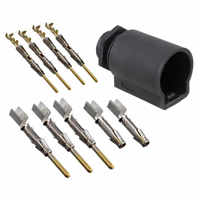


 工商网监
湘ICP备2023018690号
工商网监
湘ICP备2023018690号
