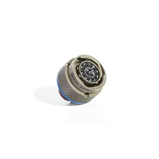
MIL-DTL-38999
Features and Application
Series II
Features and Application
Closed-Entry Socket Insert – Hard dielectric socket face
has lead-in chamfers for positive alignment of pins (even
partially bent within pre-established limits) with sockets.
MIL-DTL-38999 Series II connectors feature a bayonet
coupling mechanism with lower profile design and
rear-removable crimp contact retention system.
Interfacial Pin Insert Seal – Raised moisture barriers
around each pin, which mate into lead-in chamfers of hard
face socket insert, provide individual contact sealing. Interfacial seal is never touched by service tools.
Reduction of both size and weight were achieved through the
use of thinner shell walls and length restrictions. These design
restrictions reduced the RFI attenuation characteristics and the
“scoop” protection, while yielding an excellent general purpose,
lightweight connector. Compared to Series I, Series II connectors achieve up to 20% reduction in mated pair length, up to
39% reduction in outside diameter and up to 40% reduction in
weight (128 pin mated pair).
This family of connectors is offered in six receptacle-mounting
styles. They include square flange receptacles, for both front
and rear panel (wall) mounting; square flange receptacles, for
both front and rear panel (box) mounting; square flange receptacle with extended grommet, for front of panel (box) mounting; and jam nut receptacles which incorporate
“O” ring seals, designed for rear panel “D” hole mounting.
Elastomer Wire Sealing Grommet – Sealing over a wide
range of wire diameters is assured by a triple wire seal in
each cavity at the rear of the connector.
Superior Contact Stability – Rear release crimp contact
system features a stamped beryllium-copper retaining clip
captivated by molded-in shoulders of each contact cavity in
the insulator. A rear-inserted M81969 plastic tool expands
the tines beyond the shoulder, releasing the contact.
Shell Polarization – Alternate key/keyway positions prevent
cross mating of adjacent connectors having same insert
arrangement.
Plugs are available in two designs, with and without RFI
grounding.
Fifty-two insert arrangement per MIL-STD-1560 are tooled
and qualified to MIL-DTL-38999 Series II, utilizing 3 to 128
M39029 contacts. Contacts come in sizes 22D, 22M, 22, 20, 16
and 12, terminating wire sizes from 28 to 12 gauge.
These connectors are available in wide range of shell materials
and finishes. Aluminum shells are offered in electroless nickel,
bright cadmium, anodized, and olive drab cadmium. Other finishes such as zinc cobalt are available upon request to commercial callouts only. In addition, we offer passivated stainless steel
shells with standard environment-resisting inserts (commercial
callouts only).
Universal I/R Tool – A single, expendable plastic tool is used
for both insertion and removal of contacts.
www.conesys.com
– 22 –
sales@aero-electric.com
38999 S II
These connectors were designed for military and commercial
applications where the prime requirements are lower profile
and lighter weight.
�MIL-DTL-38999
Performance Specifications
Series II
Performance Specifications
Shell-to-Shell Conductivity
Maximum potential drop shall not exceed:
• With RFI spring fingers, finish F = 1.0 millivolt, while
finishes A and B = 2.5 millivolts.
• Without spring fingers = 200 millivolts.
• Finish C = nonconductive.
Operating Temperature Range
Finish B: -65°C to +175°C (-85°F to +347°F)
Finishes C and F: -65°C to +200°C (-85°F to +392°F)
Finish A: -65°C to +150°C (-85°F to 302°F)
38999 S II
Material and Plating Data (Finish)
B – aluminum shell, olive drab cadmium over nickel base
C – aluminum shell, black anodized finish
F – aluminum shell, electroless nickel finish
A – aluminum shell, silver to light iridescent yellow color
(bright) cadmium over electroless nickel base
Shielding Effectiveness
RFI and EMI attenuation at the specified frequencies meet
the requirements of MIL-DTL-38999.
• RFI shielding effectiveness of mated connectors with
RFI backshells is measured in a triaxial radio frequency
leakage fixture.
• EMI shielding effectiveness is measured at the interface
of mated connectors and tested by the mode-stirred technique specified in method 3008 of MIL-STD-1344.
Corrosion Resistance
Finishes A, B and C withstand 500-hour salt spray.
Finish F withstands 48-hour salt spray.
Shock and Vibration Requirements
Wired, mated connectors shall not be damaged, nor shall
there be a current interruption longer than one microsecond
when subjected to the following:
Durability
Mated connectors withstand a minimum of 250 mating
cycles for RFI plug (MS27484) and 500 cycles for MS27473
and MS27500 plugs.
Standard Shock
Mated connectors withstand a pulse of approximate half
sine wave of 300 G magnitude with duration of three
milliseconds applied in three axes per MIL-STD-1344,
method 2004.
Environmental Seal
Wired, mated connectors with specified accessories attached, shall meet the altitude-immersion test specified by
MIL-DTL-38999.
Fluid Resistance
Connectors resist specified immersions in MIL-PRF-7808,
MIL-PRF-23699, MIL-PRF-5606, M2-V Chevron oil, Coolanol
25, MIL-DTL-83133 (JP-8), MIL-DTL-5624 (JP-4, JP-5),
SAE-AMS1424 Type I, and other solvents and cleaning agents.
Vibration
Mated connectors withstand the following vibration levels:
• Random vibration per MIL-STD-1344, method 2005 test
condition VI, Letter “J”.
Voltage Rating
Service
Rating
Suggested Operating Voltage
Test Voltage
Test Voltage
Test Voltage
Test Voltage
(Sea Level)
Sea Level
50,000 Ft.
70,000 Ft.
100,000 Ft.
V RMS
V RMS
V RMS
V RMS
AC (RMS)
DC
M
400
550
1300
550
350
200
N
300
450
1000
400
260
200
I
600
850
1800
600
400
200
II
900
1250
2300
800
500
200
Note: The establishment of electrical safety factors is left
entirely to the designer, as he is in the best position to know
www.conesys.com
exactly what peak voltages, switching currents, transients, etc.,
can be expected in a particular circuit.
– 23 –
sales@aero-electric.com
�MIL-DTL-38999
Part Number Development
Series II
Military and Aero-Electric Part Number Development
Mil. Prefix
Aero Prefix
MS
AE
27473
273
T
T
12
12
B
B
35
35
P
P
A
A
-340
Class
38999 S II
Shell Type
27472 = Front, wall mount receptacle = 272 (Aero p/n)
27473 = Straight plug = 273 (Aero p/n)
27474 = Jam nut receptacle = 274 (Aero p/n)
27484 = RFI grounding plug = 284 (Aero p/n)
27497 = Rear, wall mount receptacle = 297 (Aero p/n)
27499 = Front, box mount receptacle = 299 (Aero p/n)
27500 = Standard plug with 90Þ backshell = 200 (Aero p/n)
27508 = Rear, box mount receptacle = 208 (Aero p/n)
27513 = Front, box mount rec. (long grommet) = 213 (Aero p/n)
T = With accessory thread (MS27472, 27473, 27474, 27484 & 27497)
E = Same as T in line above except connector is kitted with E-Nut
= No accessory thread, box mount (MS27499 & MS27508)
= No accessory thread, box mount, long grommet (MS27513)
P = Supplied with ring and potting boot (same shell types as “T” class)
Shell Size
8, 10, 12, 14, 16, 18, 20, 22 or 24
Finish (Material & Plating)
A = Aluminum shell, silver to light iridescent yellow (bright) cadmium over electroless nickel base
B = Aluminum shell, olive drab cadmium over electroless nickel base
C = Aluminum shell, black anodized finish (not available in MS27484)
F = Aluminum shell, electroless nickel finish
E = Stainless steel shell, passivated (Aero p/n only, n/a in AE284)
BN = Aluminum shell, Black Nickel Finish (Aero p/n only)
Insert Arrangement
See page 41-43
Contact Designator
P = Pin
A = Pin connector less pins (with intent to use non-std pin contacts)
S = Socket B = Socket connector less sockets (with intent to use non-std socket contacts)
Polarization (Keying)
N = Normal (Omitted in part number)
A, B, C, or D (B & C keyways are not available in shell size 8)
Modification (applies to Aero part numbers only)
01 = Less contacts (is not marked on the part)
340 = Connector kitted with M85049/27-XXX E-nut
341 = Connector kitted with M85049/49-2-XXX straight clamp
342 = Connector kitted with M85049/47XXX right angle clamp
Consult factory for other modifications
Note 1: Each connector is furnished with contacts unless
ordered less contacts (L/C) as follows: One spare contact
for inserts requiring 2 through 26 of each contact and two
spares for inserts with 27 or more contacts, and a minimum
of one sealing plug up to 10% of the number contacts. One
insertion/extraction tool for each contact size is also included.
www.conesys.com
Note 2: Proper part number marking has no “0” in front
of single digit shell size (8) and no “0” in front of single digit
layout. Example of each: J MS27472T8B35S and
J MS27472T10B5S. In both “N” for normal is omitted.
Please note that JAN or J marking is required immediately
in front of MS number.
– 24 –
sales@aero-electric.com
�MS27497
Rear, Wall Mount Receptacle
AE297
Bayonet Coupling, Crimp Removable, Rear Release, Low Profile/Light Weight
D
MAX
A
.447(11.35)
.442(11.23)
MAX
.069(1.75)
.058(1.47)
B
MASTER KEYWAY
.219(5.56)
MIN FULL THREAD
K GROMMET EXTENSION
38999 S II
�H
�E
MAX
GROMMET
MAX
Page 24
Page 37
Pages 41–43
Page 23
Pages 39, 40
Page 35
A
B
Maximum
(TP)
inch
mm
inch
F ACCESSORY THREAD
4 MINOR KEYWAYS
Completed Part Number
Contacts, Sealing Plugs and Tools
Insert Arrangements
Performance Specifications
Insert Availability and Contact Information
Polarization
Shell
Size
G NO. OF TEETH
BLUE COLOR BAND
4x � C
ØC
Note: See page 36 for panel thickness.
D
ØE
F
G
ØH
K
Maximum
Maximum
Accessory
Thread
No. of
Teeth
Maximum
Grommet
Extension
+.010
-.005
+.25
-.13
mm
inch
mm
inch
mm
inch
mm
UNEF-2A
inch
mm
inch
mm
8
.828
21.03
.594
15.09
.120
3.05
.988
25.10
.547
13.89
7/16-28
12
.299
7.59
.150/.090
3.81/2.29
10
.954
24.23
.719
18.26
.120
3.05
.988
25.10
.672
17.07
9/16-24
16
.427
10.85
.150/.090
3.81/2.29
12
1.047
26.59
.812
20.62
.120
3.05
.988
25.10
.844
21.44
11/16-24
20
.541
13.74
.150/.090
3.81/2.29
14
1.141
28.98
.906
23.01
.120
3.05
.988
25.10
.969
24.61
13/16-20
24
.666
16.92
.150/.090
3.81/2.29
16
1.234
31.34
.969
24.61
.120
3.05
.988
25.10
1.094
27.79
15/16-20
28
.791
20.09
.150/.090
3.81/2.29
18
1.328
33.73
1.062
26.97
.120
3.05
.988
25.10
1.219
30.96
1-1/16-18
32
.897
22.78
.150/.090
3.81/2.29
20
1.453
36.91
1.156
29.36
.120
3.05
.988
25.10
1.344
34.14
1-3/16-18
36
1.022
25.96
.150/.090
3.81/2.29
22
1.578
40.08
1.250
31.75
.120
3.05
.988
25.10
1.469
37.31
1-5/16-18
40
1.147
29.13
.150/.090
3.81/2.29
24
1.703
43.26
1.375
34.93
.147
3.73
1.056
26.82
1.594
40.49
1-7/16-18
44
1.272
32.31
.140/.040
3.56/1.02
www.conesys.com
– 25 –
sales@aero-electric.com
�MS27472
Front, Wall Mount Receptacle
AE272
Bayonet Coupling, Crimp Removable, Rear Release, Low Profile/Light Weight
D
MAX
A
.069(1.75)
.058(1.47)
.322(8.18)
.317(8.05)
MAX
B
MASTER KEYWAY
.219(5.56)
MIN FULL THREAD
K GROMMET EXTENSION
Page 24
Page 37
Pages 41–43
Page 23
Pages 39, 40
Page 35
MAX
GROMMET
G NO. OF TEETH
BLUE COLOR BAND
4x � C
38999 S II
�H
�E
F ACCESSORY THREAD
4 MINOR KEYWAYS
Completed Part Number
Contacts, Sealing Plugs and Tools
Insert Arrangements
Performance Specifications
Insert Availability and Contact Information
Polarization
A
B
Maximum
(TP)
Shell
Size
inch
mm
inch
ØC
D
+.010
-.005
+.25
-.13
mm
inch
mm
inch
ØE
F
G
ØH
K
No. of
Teeth
Maximum
Grommet
Extension
±.003
±.08
Accessory
Thread
mm
inch
mm
UNEF-2A
Maximum
inch
mm
inch
mm
8
.828
21.03
.594
15.09
.120
3.05
.932
23.67
.471
11.96
7/16-28
12
.299
7.59
.150/.090
3.81/2.29
10
.954
24.23
.719
18.26
.120
3.05
.932
23.67
.588
14.94
9/16-24
16
.427
10.85
.150/.090
3.81/2.29
12
1.047
26.59
.812
20.62
.120
3.05
.932
23.67
.748
19.00
11/16-24
20
.541
13.74
.150/.090
3.81/2.29
14
1.141
28.98
.906
23.01
.120
3.05
.932
23.67
.873
22.17
13/16-20
24
.666
16.92
.150/.090
3.81/2.29
16
1.234
31.34
.969
24.61
.120
3.05
.932
23.67
.998
25.35
15/16-20
28
.791
20.09
.150/.090
3.81/2.29
18
1.328
33.73
1.062
26.97
.120
3.05
.932
23.67
1.123
28.52
1-1/16-18
32
.897
22.78
.150/.090
3.81/2.29
20
1.453
36.91
1.156
29.36
.120
3.05
.932
23.67
1.248
31.70
1-3/16-18
36
1.022
25.96
.150/.090
3.81/2.29
22
1.578
40.08
1.250
31.75
.120
3.05
.932
23.67
1.373
34.87
1-5/16-18
40
1.147
29.13
.150/.090
3.81/2.29
24
1.703
43.26
1.375
34.93
.147
3.73
1.000
25.40
1.498
38.05
1-7/16-18
44
1.272
32.31
.140/.040
3.56/1.02
www.conesys.com
– 26 –
sales@aero-electric.com
�MS27508
Rear, Box Mount Receptacle
AE208
Bayonet Coupling, Crimp Removable, Rear Release, Low Profile/Light Weight
.757(19.23)
MAX
A
.447(11.35)
.442(11.23)
MAX
B
MASTER KEYWAY
38999 S II
MAX
Page 24
Page 37
Pages 41–43
Page 23
Pages 39, 40
Page 35
.069(1.75)
.058(1.47)
.322(8.18)
.317(8.05)
�F
4x � C
.250(6.35)
MAX
.060(1.52)
MAX
GROMMET EXTENSION
�H
�E
MAX
�F
GROMMET MAX
BLUE COLOR BAND
4 MINOR KEYWAYS
Completed Part Number
Contacts, Sealing Plugs and Tools
Insert Arrangements
Performance Specifications
Insert Availability and Contact Information
Polarization
A
B
Maximum
(TP)
Shell
Size
inch
mm
inch
Note: See page 36 for panel thickness.
ØC
ØE
ØF
ØH
+.010
-.005
+.25
-.13
±.003
±.08
mm
inch
mm
inch
mm
inch
mm
inch
Maximum
Maximum
mm
8
.828
21.03
.594
15.09
.120
3.05
.471
11.96
.547
13.89
.299
7.59
10
.954
24.23
.719
18.26
.120
3.05
.588
14.94
.672
17.07
.427
10.85
12
1.047
26.59
.812
20.62
.120
3.05
.748
19.00
.844
21.44
.541
13.74
14
1.141
28.98
.906
23.01
.120
3.05
.873
22.17
.969
24.61
.666
16.92
16
1.234
31.34
.969
24.61
.120
3.05
.998
25.35
1.094
27.79
.791
20.09
18
1.328
33.73
1.062
26.97
.120
3.05
1.123
28.52
1.219
30.96
.897
22.78
20
1.453
36.91
1.156
29.36
.120
3.05
1.248
31.70
1.344
34.14
1.022
25.96
22
1.578
40.08
1.250
31.75
.120
3.05
1.373
34.87
1.469
37.31
1.147
29.13
24
1.703
43.26
1.375
34.93
.147
3.73
1.498
38.05
1.594
40.49
1.272
32.31
www.conesys.com
– 27 –
sales@aero-electric.com
�MS27499
Front, Box Mount Receptacle
AE299
Bayonet Coupling, Crimp Removable, Rear Release, Low Profile/Light Weight
.763(19.38)
MAX
A
MAX
.069(1.75)
.058(1.47)
.322(8.18)
.317(8.05)
B
MASTER KEYWAY
.312(7.92)
MAX
�H
�E
4x � C
Page 24
Page 37
Pages 41–43
Page 23
Pages 39, 40
Page 35
38999 S II
.060(1.52)
MAX
GROMMET EXTENSION
�F
MAX
MAX
GROMMET
BLUE COLOR BAND
4 MINOR KEYWAYS
Completed Part Number
Contacts, Sealing Plugs and Tools
Insert Arrangements
Performance Specifications
Insert Availability and Contact Information
Polarization
A
B
Maximum
(TP)
Shell
Size
inch
mm
inch
ØC
ØE
ØF
ØH
+.010
-.005
+.25
-.13
±.003
±.08
mm
inch
mm
inch
mm
inch
mm
inch
Maximum
Maximum
mm
8
.828
21.03
.594
15.09
.120
3.05
.471
11.96
.453
11.51
.299
7.59
10
.954
24.23
.719
18.26
.120
3.05
.588
14.94
.578
14.68
.427
10.85
12
1.047
26.59
.812
20.62
.120
3.05
.748
19.00
.703
17.86
.541
13.74
14
1.141
28.98
.906
23.01
.120
3.05
.873
22.17
.828
21.03
.666
16.92
16
1.234
31.34
.969
24.61
.120
3.05
.998
25.35
.953
24.21
.791
20.09
18
1.328
33.73
1.062
26.97
.120
3.05
1.123
28.52
1.062
26.97
.897
22.78
20
1.453
36.91
1.156
29.36
.120
3.05
1.248
31.70
1.188
30.18
1.022
25.96
22
1.578
40.08
1.250
31.75
.120
3.05
1.373
34.87
1.312
33.32
1.147
29.13
24
1.703
43.26
1.375
34.93
.147
3.73
1.498
38.05
1.438
36.53
1.272
32.31
www.conesys.com
– 28 –
sales@aero-electric.com
�MS27474
Jam Nut Receptacle
AE274
Bayonet Coupling, Crimp Removable, Rear Release, Low Profile/Light Weight
D
G
MAX.
MASTER
KEYWAY
"O" RING
A
.105(2.67)
.084(2.13)
SS 8-22 .150(3.81)
.090(2.29)
GROMMET
SS 24 .140(3.56) EXTENSION
.040(1.02)
38999 S II
B
�J
�F
FLAT
MAX
GROMMET
H NO. OF TEETH
M ACCESSORY THREAD
HEX NUT
PER MS3186
E THREAD
3 BAYONET PINS
4 MINOR KEYWAYS
BLUE COLOR BAND
Page 24
Page 37
Pages 41–43
Page 23
Pages 39, 40
Page 35
Completed Part Number
Contacts, Sealing Plugs and Tools
Insert Arrangements
Performance Specifications
Insert Availability and Contact Information
Polarization
A
Shell
Size
PANEL THICKNESS
.109(2.77)
.062(1.57)
B
D
E
ØF
±.005
±.13
+.001
-.006
+.03
-.15
±.016
±.41
Jam Nut Thread
Class 2A
±.003
±.08
inch
mm
inch
mm
inch
mm
inch
mm
G
H
ØJ
M
Maximum
No. of
Teeth
Maximum
Accessory
Thread
inch
mm
inch
mm
UNEF-2A
8
.438
11.13
.817
20.75
1.250
31.75
7/8-20UNEF
.471
11.96
.937
23.80
12
.299
7.59
7/16-28
10
.438
11.13
.941
23.90
1.375
34.93
1-20UNEF
.588
14.94
.937
23.80
16
.427
10.85
9/16-24
12
.438
11.13
1.065
27.05
1.500
38.10
1-1/8-18UNEF
.748
19.00
.937
23.80
20
.541
13.74
11/16-24
14
.438
11.13
1.190
30.23
1.625
41.28
1-1/4-18UNEF
.873
22.17
.937
23.80
24
.666
16.92
13/16-20
16
.438
11.13
1.320
33.53
1.781
45.24
1-3/8-18UNEF
.998
25.35
.937
23.80
28
.791
20.09
15/16-20
18
.438
11.13
1.440
36.58
1.890
48.01
1-1/2-18UNEF
1.123
28.52
.937
23.80
32
.897
22.78
1-1/16-18
20
.464
11.79
1.565
39.75
2.016
51.21
1-5/8-18UNEF
1.248
31.70
.931
23.65
36
1.022
25.96
1-3/16-18
22
.464
11.79
1.690
42.93
2.140
54.36
1-3/4-18UNS
1.373
34.87
.931
23.65
40
1.147
29.13
1-5/16-18
24
.464
11.79
1.815
46.10
2.265
57.53
1-7/8-16UN
1.498
38.05
.984
24.99
44
1.272
32.31
1-7/16-18
www.conesys.com
– 29 –
sales@aero-electric.com
�MS27513
Long Grommet, Front, Box Mount Receptacle
AE213
Bayonet Coupling, Crimp Removable, Rear Release, Low Profile/Light Weight
.907(23.04)
MAX
A
MAX
B
MASTER KEYWAY
.069(1.75)
.058(1.47)
.516(13.11)
MAX
.322(8.18)
.317(8.05)
.312(7.92)
MAX
MAX
GROMMET
38999 S II
�H
�E
�F
MAX
BLUE COLOR BAND
4x � C
4 MINOR KEYWAYS
Page 24
Page 37
Pages 41–43
Page 23
Pages 39, 40
Page 35
Completed Part Number
Contacts, Sealing Plugs and Tools
Insert Arrangements
Performance Specifications
Insert Availability and Contact Information
Polarization
A
B
Maximum
(TP)
Shell
Size
inch
mm
inch
ØC
ØE
ØF
ØH
+.010
-.005
+.25
-.13
±.003
±.08
mm
inch
mm
inch
mm
inch
mm
inch
Maximum
Maximum
mm
8
.828
21.03
.594
15.09
.120
3.05
.471
11.96
.453
11.51
.299
7.59
10
.954
24.23
.719
18.26
.120
3.05
.588
14.94
.578
14.68
.427
10.85
12
1.047
26.59
.812
20.62
.120
3.05
.748
19.00
.703
17.86
.541
13.74
14
1.141
28.98
.906
23.01
.120
3.05
.873
22.17
.828
21.03
.666
16.92
16
1.234
31.34
.969
24.61
.120
3.05
.998
25.35
.953
24.21
.791
20.09
18
1.328
33.73
1.062
26.97
.120
3.05
1.123
28.52
1.062
26.97
.897
22.78
20
1.453
36.91
1.156
29.36
.120
3.05
1.248
31.70
1.188
30.18
1.022
25.96
22
1.578
40.08
1.250
31.75
.120
3.05
1.373
34.87
1.312
33.32
1.147
29.13
24
1.703
43.26
1.375
34.93
.147
3.73
1.498
38.05
1.438
36.53
1.272
32.31
www.conesys.com
– 30 –
sales@aero-electric.com
�MS27473
Straight Plug
AE273
Bayonet Coupling, Crimp Removable, Rear Release, Low Profile/Light Weight
38999 S II
Page 24
Page 37
Pages 41–43
Page 23
Pages 39, 40
Page 35
Completed Part Number
Contacts, Sealing Plugs and Tools
Insert Arrangements
Performance Specifications
Insert Availability and Contact Information
Polarization
ØA
ØC
D
E
ØF
G
H
Minimum
Maximum
No of
Teeth
Accessory
Thread
Maximum
Maximum
Grommet
Extension
Shell
Size
inch
mm
inch
mm
UNEF-2A
inch
mm
inch
mm
inch
mm
8
.337
8.56
.299
7.59
12
7/16-28
.750
19.05
.916
23.27
.150/.090
3.81/2.29
10
.465
11.81
.427
10.85
16
9/16-24
.859
21.82
.916
23.27
.150/.090
3.81/2.29
12
.557
14.15
.541
13.74
20
11/16-24
1.031
26.19
.916
23.27
.150/.090
3.81/2.29
14
.702
17.83
.666
16.92
24
13/16-20
1.156
29.36
.916
23.27
.150/.090
3.81/2.29
16
.827
21.01
.791
20.09
28
15/16-20
1.281
32.54
.916
23.27
.150/.090
3.81/2.29
18
.927
23.55
.897
22.78
32
1-1/16-18
1.406
35.71
.916
23.27
.150/.090
3.81/2.29
20
1.052
26.72
1.022
25.96
36
1-3/16-18
1.531
38.89
.916
23.27
.150/.090
3.81/2.29
22
1.177
29.90
1.147
29.13
40
1-5/16-18
1.641
41.68
.916
23.27
.150/.090
3.81/2.29
24
1.302
33.07
1.272
32.31
44
1-7/16-18
1.766
44.86
.984
24.99
.140/.040
3.56/1.02
www.conesys.com
– 31 –
sales@aero-electric.com
�MS27484
RFI Grounding Plug
AE284
Bayonet Coupling, Crimp Removable, Rear Release, Low Profile/Light Weight
38999 S II
Page 24
Page 37
Pages 41–43
Page 23
Pages 39, 40
Page 35
Completed Part Number
Contacts, Sealing Plugs and Tools
Insert Arrangements
Performance Specifications
Insert Availability and Contact Information
Polarization
ØA
ØC
D
E
ØF
G
H
Minimum
Maximum
No of
Teeth
Accessory
Thread
Maximum
Maximum
Grommet
Extension
Shell
Size
inch
mm
inch
mm
UNEF-2A
inch
mm
inch
mm
inch
mm
8
.337
8.56
.299
7.59
12
7/16-28
.750
19.05
.916
23.27
.150/.090
3.81/2.29
10
.465
11.81
.427
10.85
16
9/16-24
.859
21.82
.916
23.27
.150/.090
3.81/2.29
12
.557
14.15
.541
13.74
20
11/16-24
1.031
26.19
.916
23.27
.150/.090
3.81/2.29
14
.702
17.83
.666
16.92
24
13/16-20
1.156
29.36
.916
23.27
.150/.090
3.81/2.29
16
.827
21.01
.791
20.09
28
15/16-20
1.281
32.54
.916
23.27
.150/.090
3.81/2.29
18
.927
23.55
.897
22.78
32
1-1/16-18
1.406
35.71
.916
23.27
.150/.090
3.81/2.29
20
1.052
26.72
1.022
25.96
36
1-3/16-18
1.531
38.89
.916
23.27
.150/.090
3.81/2.29
22
1.177
29.90
1.147
29.13
40
1-5/16-18
1.641
41.68
.916
23.27
.150/.090
3.81/2.29
24
1.302
33.07
1.272
32.31
44
1-7/16-18
1.766
44.86
.984
24.99
.140/.040
3.56/1.02
www.conesys.com
– 32 –
sales@aero-electric.com
�MS27500
Plug with 90° Backshell
AE200
Bayonet Coupling, Crimp Removable, Rear Release, Low Profile/Light Weight
� F MAX
COUPLING NUT
BLUE COLOR BAND
MASTER KEY
38999 S II
�A
MIN
SHELL
Y
MAX
W
MAX
4 MINOR KEYS
L MAX
Page 24
Page 37
Pages 41–43
Page 23
Pages 39, 40
Page 35
Completed Part Number
Contacts, Sealing Plugs and Tools
Insert Arrangements
Performance Specifications
Insert Availability and Contact Information
Polarization
ØA
ØF
Minimum
Shell
Size
inch
L
Maximum
W
Maximum
Y
Maximum
Maximum
mm
inch
mm
inch
mm
inch
mm
inch
mm
8
.337
8.56
.750
19.05
1.859
47.22
1.000
25.40
.828
21.03
10
.465
11.81
.859
21.82
1.859
47.22
1.032
26.21
.891
22.63
12
.557
14.15
1.031
26.19
1.938
49.23
1.094
27.79
1.016
25.81
14
.702
17.83
1.156
29.36
2.125
53.98
1.219
30.96
1.141
28.98
16
.827
21.01
1.281
32.54
2.281
57.94
1.281
32.54
1.255
31.88
18
.927
23.55
1.406
35.71
2.312
58.72
1.344
34.14
1.469
37.31
20
1.052
26.72
1.531
38.89
2.375
60.33
1.375
34.93
1.550
39.37
22
1.177
29.90
1.641
41.68
2.531
64.29
1.438
36.53
1.675
42.55
24
1.302
33.07
1.766
44.86
2.828
71.83
1.719
43.66
1.800
45.72
www.conesys.com
– 33 –
sales@aero-electric.com
�M38999/10
Dummy Stowage Receptacle
AE210
Dummy Stowage Receptacle, Bayonet Coupling
38999 S II
Part Number Configuration
MIL. Prefix
Aero Prefix
M38999/
AE2
10
10-
XX
XX
B
B
Shell Type
10 = receptacle, dummy stowage, bayonet coupling
Shell Size
8 THRU 24 (Note: single digit for shell size 8)
Material Finish
B = Aluminum, Cadmium Olive Drab
A = Aluminum, Bright Cadmium over Nickel base (Aero p/n only)
F = Aluminum shell, Electroless Nickel finish (Aero p/n only)
S = Stainless steel shell, passivated (Aero p/n only)
BN = Aluminum, Black Nickel (Aero p/n only)
BZ = Bronze (Aero p/n only)
www.conesys.com
SHELL
SIZE
ØA
+.001
-.005
ØT
+.010
-.005
S
MAX
8
.473
.120
.828
10
.590
.120
.954
12
.750
.120
1.047
14
.875
.120
1.141
16
1.000
.120
1.234
18
1.125
.120
1.328
20
1.250
.120
1.453
22
1.375
.120
1.578
24
1.500
.147
1.703
– 34 –
sales@aero-electric.com
�MIL-DTL-38999
Polarization
Series II
Keying Positions
NORMAL
C°
38999 S II
N°
A°
MASTER
KEYWAY
B°
D°
10°
DATUM
F
Notes:
1. Mating face of receptacle shown (plug is opposite).
2. The master keyway (key) has various positions relative
to DATUM F; the minor keyways (keys) remain fixed as
shown. In the Normal position, the master keyway (key)
is 100° from DATUM F.
3. The angles for a given connector are the same whether it
contains pin or socket inserts.
4. The insert arrangement does not rotate relative to master
keyway (key).
Keying Positions
BSC
Shell
Size
N°
A°
B°
C°
D°
8
100
82
-
-
118
10
100
86
72
128
114
12
100
80
68
132
120
14
100
79
66
134
121
16
100
82
70
130
118
18
100
82
70
130
118
20
100
82
70
130
118
22
100
85
74
126
115
24
100
85
74
126
115
www.conesys.com
– 35 –
sales@aero-electric.com
�MIL-DTL-38999 Series II
Flange and Jam Nut Receptacle
Panel Cutouts
Panel Cutouts
JAM NUT
FLANGE MOUNT
D MAX
PANEL THICKNESS
38999 S II
4x � C
.109(2.77)
.062(1.57)
PANEL THICKNESS
�B
MIN
F
�E
A
Note 1: Flange Mounting Dimensions (Ø B cutout and
D max) listed only for back of panel mounting (MS27497
and MS27508).
Note 2: D max includes mounting hardware.
Flange and Jam Nut Mounting Dimensions
A
ØB
(TP)
Minimum
Shell
Size
inch
mm
inch
ØC
D
ØE
±.005
±.13
mm
inch
mm
inch
mm
Maximum
F
+.010
-.000
+.25
-.00
+.000
-.010
+.00
-.25
inch
mm
inch
mm
8
.594
15.09
.557
14.15
.128
3.25
.146
3.71
.885
22.48
.830
21.08
10
.719
18.26
.682
17.32
.128
3.25
.146
3.71
1.010
25.65
.955
24.26
12
.812
20.62
.854
21.69
.128
3.25
.146
3.71
1.135
28.83
1.085
27.56
14
.906
23.01
.979
24.87
.128
3.25
.146
3.71
1.260
32.01
1.210
30.73
16
.969
24.61
1.104
28.04
.128
3.25
.146
3.71
1.385
35.18
1.335
33.91
18
1.062
26.97
1.229
31.22
.128
3.25
.146
3.71
1.510
38.35
1.460
37.08
20
1.156
29.36
1.354
34.39
.128
3.25
.168
4.27
1.635
41.53
1.585
40.26
22
1.250
31.75
1.479
37.57
.128
3.25
.168
4.27
1.760
44.70
1.709
43.42
24
1.375
34.93
1.604
40.74
.154
3.91
.168
4.27
1.885
47.88
1.835
46.61
www.conesys.com
– 36 –
sales@aero-electric.com
�MIL-DTL-38999
Contacts, Tools and Seal Plugs
Series II
Contacts, Plastic Insertion/Removal Tools and Seal Plugs
Application
Pin Contacts
Socket Contacts
Insertion/Removal Tools
Plastic
Contact
Size
38999 S II
Type
Military No.
Military No.
22D
Power/Signal
M39029/58-360
M39029/57-354
22M*
Power/Signal
M39029/58-361
M39029/57-355
22*
Power/Signal
M39029/58-362
M39029/57-356
20
Power/Signal
M39029/58-363
M39029/57-357
16
Power/Signal
M39029/58-364
M39029/57-358
Coax
M39029/76-424
M39029/78-432
Power/Signal
M39029/58-365
16 Coax
12
Seal Plugs
Military No.
Military No.
M81969/14-01
MS27488-22-1
—
MS27488-20-1
M81969/14-10
MS27488-16-1
M81969/14-03
M39029/57-359
MS27488-12-1
M81969/14-04
Positioner
Positioner
Insertion Tool
Extraction Tool
For Pin Contacts
For Socket Contacts
Metal
Metal
Crimping and Metal Insertion/Extraction Tools
Crimp Tool
Contact
Size/Type
Military No.
Military No.
Military No.
Military No.
Military No.
22D, 22M*
M22520/2-01
M22520/2-09
M22520/2-06
M81969/8-01
M81969/8-02
22*
M22520/2-01
M22520/2-09
M22520/2-06
M81969/8-03
M81969/8-04
M81969/8-05
M81969/8-06
M81969/8-07
M81969/8-08
M81969/8-09
M81969/8-10
M22520/1-01
M22520/1-04
M22520/1-04
M22520/2-01
M22520/2-10
M22520/2-10
16
M22520/1-01
M22520/1-04
M22520/1-04
16 Coax Inner
M22520/2-01
M22520/2-35
M22520/2-35
16 Coax Outer
M22520/4-01
M22520/4-02
M22520/4-02
12
M22520/1-01
M22520/1-04
M22520/1-04
20
Contact and Wire Data
Test Current Voltage
Contact
Size
DC Test
Max. Drop
Crimp Well Data
Well Dia.
Wire Range
Finished Wire Ø Range
Minimum Well Dept
Minimum
2
Maximum
Amps
Millivolts
inch
inch
mm
AWG
mm
inch
mm
inch
mm
22D
5.0
73
.0345 ±.0010
.141
3.58
28-22
.08-.33
.030
.76
.054
1.37
22M*
3.0
45
.028 ±.001
.141
3.58
28-24
.08-.20
.030
.76
.050
1.27
22*
5.0
73
.0365 ±.0010
.141
3.58
26-22
.13-.33
.034
.86
.060
1.52
20
7.5
55
.047 ±.001
.209
5.31
24-20
.20-.52
.040
1.02
.083
2.11
16
13.0
49
.067 ±.001
.209
5.31
20-16
.52-1.31
.065
1.65
.109
2.77
12
23.0
42
.100 ±.002
.209
5.31
14-12
2.08-3.31
.097
2.46
.142
3.61
* Inactive for new design
Note 1: Test Current and Maximum Voltage Drop when
tested with silver-plated wire at 25°C.
www.conesys.com
Note 2: Size 16 coax contacts purchased in bulk.
– 37 –
sales@aero-electric.com
�MIL-DTL-38999
Contact Installation Instructions
Series II
Contact Installation
Instructions
3. Place the correct insertion tool on the contact so that the
wire runs along the groove in the tool. (Tool tip will butt
against the shoulder.) Hold the plug or receptacle body
firmly.
Crimping Contacts
1. Select the appropriate crimp tool and ensure that the
proper crimp head positioner is used.
2. Cycle the tool to be sure the indentors are open.
3. Determine the correct selector setting for the wire size
from the data plate on the positioner (turret head
assembly) and set the selector knob on the crimp tool
to match.
4.1 If contacts are not inserted all the way prior to
removing insertion tool, do not try to reinsert the
insertion tool. Instead, remove the contact and try
again; otherwise reinserting the insertion tool may
damage the inside of the contact cavity.
4. Place the contact, mating end first, into the tool.
5. Remove tool and check the face of the connector for
proper contact installation. Proper installation may also
be checked by pulling back lightly on the wire to make
sure the contact is properly seated.
5. Insert the stripped wire into the hollow end of the
contact. Be sure the wire is inserted as far as it will go.
6. Close the tool completely to crimp. Unless the tool is
closed completely, the tool will not release the contact.
Completion
After all the cavities have been filled, slide the hardware back
into position on the connector and tighten.
7. Remove the crimped contact from the tool. Check the
inspection hole to verify that the wire is fully inserted.
Insertion of Contacts
1. Before inserting the contacts, unscrew the accessories
(clamps, backshells or adapters) from rear of plug or
receptacle. Slide the hardware over the wire bundle in
the proper order for reassembly after all the contacts
are inserted.
Extraction of Contacts (Rework)
1. Slide the hardware back over the wire bundle.
2. Select the appropriate tool. Place the wire into the extraction tool of the pin or socket.
3. Slowly slide the extraction tool down wire into the contact
cavities until the tool tip bottoms against the contact
shoulder, expanding the clip retaining tines. Hold the
wire firmly in the tool and pull the wired contact and tool
straight out of the rear of the insulator.
2. To assist insertion of contacts, lubricate insulator
(grommet) cavities with isopropyl alcohol. Alcohol will
evaporate and will not leave a conductive film. Caution:
Never use any lubricant other than isopropyl alcohol.
Size
Pin Contact
Socket Contact
Basic Crimp Tool
Pin Positioner
Socket Positioner
Insertion/Removal Tool
22D
M39029/58-360
M39029/57-354
M22520/2-01
M22520/2-09
M22520/2-06
M81969/14-01
22M
M39029/58-361
M39029/57-355
M22520/2-01
M22520/2-09
M22520/2-06
M81969/14-01
22
M39029/58-362
M39029/57-356
M22520/2-01
M22520/2-09
M22520/2-06
M81969/14-01
M22520/1-01
M22520/1-04 Red
M22520/1-04 Red
M22520/2-01
M22520/2-10
M22520/2-10
20
M39029/58-363
M39029/57-357
M81969/14-10
16
M39029/58-364
M39029/57-358
M22520/1-01
M22520/1-04 Blue
M22520/1-04 Blue
M81969/14-03
12
M39029/58-365
M39029/57-359
M22520/1-01
M22520/1-04 Yellow
M22520/1-04 Yellow
M81969/14-04
For coax contacts refer to instructions supplied with contacts.
www.conesys.com
– 38 –
sales@aero-electric.com
38999 S II
4. Beginning with a center cavity, insert the contact into
the insulator with a slow, even pressure until the contact
snaps into position. Make sure the contact and tool are
held perpendicular to the face of the insert during the
contact installation or the grommet could be damaged.
�MIL-DTL-38999 Series II
Insert Availability and Contact Information
per MIL-STD-1560
Insert Availability and Contact Information
Insert
Arrangement
Aero-Electric
Service
Status
Total
Quantity of Contacts
No. of
(by Size)
38999 S II
Series II
QPL’d
Tooled
Rating
Contacts
8-6*
8-35
8-98
10-5
10-13*
10 -35
10-98
10-99
12-3
12-4
12-8
12-22*
12-35
12-98
14-5
14-15
14-18
14-35
14-37*
14-97
16-6
16 -8
16 -26
16 -35
16-55*
16-99
18-11
18-28
18-30
18-32
18-35
18-53**
18-66*
Yes
Yes
Yes
Yes
Yes
Yes
Yes
Yes
Yes
Yes
Yes
Yes
Yes
Yes
Yes
Yes
Yes
Yes
Yes
Yes
Yes
Yes
Yes
Yes
Yes
Yes
Yes
Yes
Yes
Yes
Yes
Yes
Yes
Yes
Yes
Yes
Yes
Yes
Yes
Yes
Yes
Yes
Yes
Yes
Yes
Yes
Yes
Yes
Yes
Yes
Yes
Yes
Yes
Yes
Yes
Yes
Yes
Yes
Yes
Yes
Yes
Yes
Yes
Yes
Yes
Yes
M
M
I
I
M
M
I
I
II
I
I
M
M
I
II
I
I
M
M
I
I
II
I
M
M
I
II
I
I
I
M
M
M
6
6
3
5
13
13
6
7
3
4
8
22
22
10
5
15
18
37
37
12
6
8
26
55
55
23
11
28
30
32
66
53
66
22D
22M
22
20
16
12
6
6
3
5
13
13
6
7
3
4
8
22
22
10
14
18
5
1
37
37
8
4
6
8
26
55
55
21
26
29
32
2
11
2
1
66
53
66
See next page for Shell Sizes 20 thru 24 layouts.
* Not approved for new design. Tooled and qualified but their
separate pictorials are not shown on pages 41 thru 43, as
they are the same as corresponding (-35) layouts that take
the same quantity of 22D contacts, but are supplied with
22M contacts instead.
** Not approved for new design. Pictorial is shown on page 42.
www.conesys.com
– 39 –
sales@aero-electric.com
�MIL-DTL-38999 Series II
Insert Availability and Contact Information
per MIL-STD-1560
Insert Availability and Contact Information (continued)
Insert Arrangement
Aero-Electric
Service
Status
Total
Quantity of Contacts
No. of
(by Size)
QPL’d
Tooled
Rating
Contacts
20-1*
20-16
20-35
20-39
20-41
22-1*
22-2***
22-21
22-32
22-35
22-53
22-55
24-1*
24-4
24-19
24-24
24-29
24-35
24-61
Yes
Yes
Yes
Yes
Yes
Yes
Yes
Yes
Yes
Yes
Yes
Yes
Yes
Yes
Yes
Yes
Yes
Yes
Yes
Yes
Yes
Yes
Yes
Yes
Yes
Yes
Yes
Yes
Yes
Yes
Yes
Yes
Yes
Yes
Yes
Yes
Yes
Yes
M
II
M
I
I
M
M
II
I
M
I
I
M
I
I
I
I
M
I
79
16
79
39
41
100
85
21
32
100
53
55
128
56
19
24
29
128
61
22D
22M
22
20
16
12
79
16
79
37
41
2
38999 S II
Series II
100
85
21
32
100
53
55
128
48
8
12
29
19
12
128
61
* Not approved for new design. Tooled and qualified but their separate
pictorials are not shown on pages 41 thru 43, as they are same as
corresponding (-35) layouts that take the same quantity of 22D contacts, but are supplied with 22M contacts instead.
www.conesys.com
– 40 –
sales@aero-electric.com
�MIL-STD-1560
Insert Arrangements (Pin Front View)
for MIL-DTL-38999 Series II Connectors
Insert Arrangements Views
5
C
1
6
4
3
A
E
A
1
A
10
2
11
9
B
2
D
8-98
3 # 20, I
8-35
6 # 22D, M
38999 S II
C
10-5
5 # 20, I
A
A
8
B
C
G
D
H
F
13
12
7
6
14
1
21
15
12-3
3 # 16, II
10-98
6 # 20, I
L A
L
K
B
M
R
J
K
N
H
C
J
D
P
H
E
G
T
U
S
R
G
F
31
B
J
F
12-35
22 # 22D, M
K
A
E
C
B
D
M
G
F
F
A
A
E
G
D
D
F
A
S
P
T
J
E
F
W
X
G
H
16-26
26 # 20, I
www.conesys.com
32
C
H
F
D
47
P
53
Y
55
3
52
9
16
24
31
39
46
16-35
55 # 22D, M
16-8
8 # 16, II
C
Z
K
H
U
B
V
X
M
E
W
J H
F
G
G
C
L
E
16-99
2 # 16, 21 # 20, I
– 41 –
18-11
11 # 16, II
V
C
W
e
D
X
b
N
E
Y
a
M
D
F
d
c
P
B
U
R
D
K
A
T
S
A
J
N
L
D
E
16-6
6 # 12, I
B
T
S
C
E
14-97
4 # 16, 8 # 20, I
A
R
40
1
V
c
Y
K
25
D
U
Z
17
4
C
b
a
N
M
L
10
B
R
14-35
37 # 22D, M
14-18
18 # 20, I
B
B
C
14-5
1 # 16, 14 # 20, I
C
14-5
5 # 16, II
B
H
E
D
12-98
10 # 20, I
A
L
J
21
C
P
10-99
7 # 20, I
E
1
B
B
C
C
D
A
N
M
A
H
G
K
12-8
8 # 20, I
12-4
4 # 16, I
A
G
E
D
B
E
C
F
B
C
5
22
B
F
D
4
10-35
13 # 22D, M
A
B
E
3
F
Z
L
G
K
J
18-28
2 # 16, 26 # 20, I
sales@aero-electric.com
�MIL-STD-1560
Insert Arrangements (Pin Front View)
for MIL-DTL-38999 Series II Connectors
Insert Arrangements Views
S
R
P
d
U
e
b
M
g
f
W
a
L
D
V
E
J
a
24
U
31
N
C
21
29
39
N
58
67
12
75
W
R
L
K
11
C
S
28
38
47
57
U
J
81
19
66
S
R
P
k
h
N
n
m
z
AA
f
K
HH
FF
q
CC
DD
J
s
t
w
d
v
c
u
a
b
n
C
W
X
Y
x
e
r
EE
g
L
V
BB
GG
y
M
p
S
k
D
E
F
Z
G
H
22-53
53 # 20, I
m
z
R
P
j
AA
GG
q
N H
M
x
FF
DD
EE
v
f
L
Y
Z
a
d
e
K
G
J
94
97
5
99
6
10 0
15
24
T
S
q
LL
p
E
55
66
76
85
KK
AA
BB
n
m
N
M
f
24-4
B
K
U
P
V
C
D
R
H
J
K
N
G
h
k
L
A
L
F
z
g
DD
CC
45
93
D
e
y
HH
JJ
EE
r
34
M
C
d
8 # 16, 48 # 20, I
– 42 –
86
B
c
x
GG
P
22-55
55 # 20, I
A
s
U
R
H
77
22-35
100 # 22D, M
b
FF
E
b
c
67
96
F
w
t
V
t
u
56
95
7
a
Z
u
D
F
46
4
E
v
W
X
HH
w
g
X
C
r
35
3
U
V
Y
CC s
K
L
2
T
e
X
B
BB
H
J
1
C
d
25
16
8
B
S
G
W
G
20-41
41 # 20, I
D
f
A
p
c
d
e
M
22-32
32 # 20, I
y
i
P
N
c
H
* Inactive for new design.
** Not MIL-STD-1560 layout (not QPL’d.).
www.conesys.com
Y
F
V
p
q
f
b
98
K
J
G
U
U
g
R
F
n
r
W
T
B
G
R
i
22-21
21 # 16, II
A
T
D
T
H
22-2*
85 # 22, M
S
E
a
t
A
P
g
E
74
s
H
D
Z
m
h
K
h
Z
V
85
F
T
J
b
a
X
4
b
c
N
M
B
P
L
82
1
E
C
Y
k
i
20-39
2 # 16, 37 # 20, I
A
M
5
a
B
X
j
U
D
d
e
M
20-35
79 # 22D, M
48
p
L
20-16
16 # 16, 11
20
n
f
11
E
F
m
q
N
41
Z
r
A
W
V
C
Y
k
g
D
G
j
P
61
R
11
18-53*
53 #22, M
B
X
h
S
R
71
79
P
A
W
i
T
S
50
42
38999 S II
51
B
33
18-35
66 #22D, M
V
M
31
57
16
H
A
K
H
63
1
L
52
66
9
18-32
32 # 20, I
18-30
1 # 16, 29 # 20, I
J
3
F
G
J
K
G
H
51
53
E
Y
Z
L
64
1
b
M
21
58
X
h
F
Y
1
51
D
g
c
N
X
Z
K
j
43
C
W
f
d
P
34
4
V
e
R
C
25
10
B
U
T
c
N
S
B
17
A
T
A
T
J
H
E
S
G
F
24-19
19 # 12, I
sales@aero-electric.com
�MIL-STD-1560
Insert Arrangements (Pin Front View)
for MIL-DTL-38999 Series II Connectors
Insert Arrangements Views
A
P
B
N
R
C
Y
M
D
T
38999 S II
W
J
H
G
24-24
12 # 12, 12 # 16, I
www.conesys.com
L
F
d
94
105
1
Y
V
X
122
W
V
125
4
K
7
G
24
H
J
35
47 5870
81 93
24-35
128 # 22D, M
24-29
29# 16, I
– 43 –
104
11 4
FF
A
b
B
c
v
GG
s
d
w
HH
NN
JJ
KK
MM
CC
n
P
N
k
M
L
H
i
j
F
G
h
AA
BB
m
E
g
z
LL
DD
D
f
y
EE
P
C
e
x
PP
q
R
121
14
t
r
S
F
u
U
T
W
X
Z
a
Y
115
E
e
Z
E
U
V
71 82
D
f
M
a
36 48 59
U
c
N
25
8
C
a
X
15
B
T
b
S
K
S
P
Z
L
A
R
J
K
24-61
61 # 20, I
sales@aero-electric.com
�