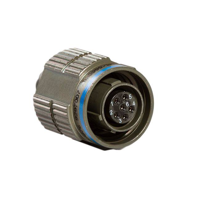
MIL-DTL-38999
Features and Application
Series III
Features and Application
Universal I/R Tool – A single, expendable plastic tool is used
for both insertion and removal of contacts.
MIL-DTL-38999 Series III is the newest cylindrical connector
designed for highest performance capabilities used in both
general purpose and severe environment applications.
Scoop-Proof Design – Recessed pins in elongated shells
minimize the possibility for contact damage. In a blind
mating application, mating shells cannot “scoop” the pins,
and cause a shorting or bending of contacts.
These connectors feature an improved “one-turn” coupling
system, utilizing self-locking acme thread. Acme threads
provide coupling durability, while thicker wall sections and
greater coupling surface area improve strength and shock
resistance. Blunting of the threads on both receptacle and
plug coupling nut eliminates cross threading.
Closed-Entry Socket Insert – Hard dielectric socket face
has lead-in chamfers for positive alignment of pins (even
partially bent within pre-established limits) with sockets.
Elongated mounting holes permit the Series III Connector to
intermount with various existing Mil-spec flange mounted
receptacles, giving it a design replacement advantage.
Elastomer Wire Sealing Grommet – Sealing over a wide
range of wire diameters is assured by a triple wire seal in
each cavity at the rear of the connector.
Wall mount receptacle, jam nut receptacle and straight
self-locking RFI plug are offered in 9 shell sizes and 54 insert
arrangements utilizing M39029 contacts in sizes 22D, 20, 16,
12, 10 power and 8 twinax.
Superior Contact Stability – Rear release crimp contact
system features a stamped beryllium-copper retaining clip
captivated by molded-in shoulders of each contact cavity in
the insulator. A rear-inserted M81969 plastic tool expands
the tines beyond the shoulder, releasing the contact.
These connectors are available in wide range of shell materials
and finishes. Aluminum shells are offered in electroless nickel
and olive drab cadmium. Other finishes such as anodic and
zinc cobalt are available upon request to commercial callouts
only. In addition, we offer stainless steel shells (both passivated
and electro-deposited nickel plated) with firewall inserts, and
for highly corrosive environments, nickel-aluminum-bronze
shells with standard environment-resisting inserts (commercial callouts only).
Metric Accessory Thread – Metric thread results in
additional wall thickness giving greater strength and shock
resistance.
Twinax Contacts – Aero Electric is Qualified to make and
supply M39029/90-529 and M39029/91-530 size 8 Twinax
contacts used in 38999 III connectors. Please consult factory
even when needing to buy just the contacts.
MIL-STD-1560 Insert Arrangements – Series III connectors
use insert patterns and contacts common to Series I,
making for an easy transition from bayonet to triple-lead,
acme-thread, self-locking coupling.
Metal-to-Metal Bottoming – This feature precludes relative
shell-to-shell motion, which may result in ordinary connector
wear and moisture entrapment.
Lockwiring Eliminated – Self-locking quick coupling plug
eliminates the need for lockwiring.
Firewall Capability - Stainless steel shells in both K and S
firewall classes are offered.
www.conesys.com
– 44 –
sales@aero-electric.com
38999 S III
Interfacial Pin Insert Seal – Raised moisture barriers
around each pin, which mate into lead-in chamfers of
hard face socket insert, provide individual contact sealing.
Interfacial seal is never touched by service tools.
�MIL-DTL-38999
Performance Specifications
Series III
Performance Specifications
Environmental Seal
Wired, mated connectors with specified accessories
attached, shall meet the altitude-immersion test specified in
MIL-DTL-38999.
Operating Temperature Range
Classes F, K, S and BZ*: -65°C to +200°C (-85°F to +392°F)
Classes W, T, Z, BN* and ZC*: -65°C to +175°C (-85°F to +347°F)
38999 S III
Material and Finish Data (Class)
F – aluminum shell, electroless nickel finish
K – stainless steel shell, passivated, firewall
S – stainless steel shell, electrodeposited nickel, firewall
T *- aluminum shell, nickel flourocarbon polymer finish
W– aluminum shell, olive drab cadmium over nickel base
Z *- aluminum shell, zinc nickel finish
BN* -aluminum shell, black nickel finish
BZ* – aluminum nickel bronze shell, std insert
ZC*– aluminum shell, zinc cobalt finish
Shell-to-Shell Conductivity
Maximum potential drop shall not exceed:
• Classes F and S = 1.0 millivolt.
• Class W = 2.5 millivolts, Class K = 10.0 millivolts
Shock and Vibration Requirements
Wired, mated connectors shall not be damaged, nor shall
there be a current interruption longer than one microsecond
when subjected to the following:
Shock
Pulse of approximate half sine wave of 300 G ± 15 percent magnitude with duration of 3 ± 1 milliseconds applied in three axes.
Corrosion Resistance
Military Classes K, W and S, withstand 500-hour salt spray.Class
F withstands 48-hour salt spray.Commerical RoHS Classes:
BN*, BZ*,ZC*. Consult factory for T and Z class availability.
High Impact Shock
When mounted as specified in MIL-S-901, grade A, a drop
of a 400 lb. Hammer from 1 foot, 3 feet and 5 feet applied to
connector in three axes, totaling nine impacts.
Durability
Minimum of 500 mating cycles.
Fluid Resistance
Connectors resist specified immersions in MIL-PRF-7808,
MIL-PRF-23699, MIL-PRF-5606, M2-V Chevron oil, Coolanol
25, MIL-DTL-83133 (JP-8), MIL-DTL-5624 (JP-4, JP-5),
SAE-AMS1424 Type I, and other solvents and cleaning agents.
Shielding Effectiveness
RFI and EMI attenuation at the specified frequencies meet
the requirements of MIL-DTL-38999.
• RFI shielding effectiveness of mated connectors with RFI backshells is measured in a triaxial radio frequency leakage fixture.
• EMI shielding effectiveness is measured at the interfaceof
mated connectors and tested by the mode-stirred technique specified in method 3008 of MIL-STD-1344.
Vibration
Wired and mated connectors withstand the following
vibration levels:
• Sine vibration where connector samples with simulated
accessory load are subjected to simple harmonic motion
from 10 to 2,000 Hz in three mutually perpendicular axes,
in 20 minute sweeps, for 12 hours in each axis at velocity of
254 mm/sec from 10-50 Hz, displacement of 1.5 mm from
50-140Hz and acceleration of 60G from 140-2,000Hz.
• Random Vibration per MIL-STD-1344, method 2005,
test condition V at ambient temperature and test
condition VI, Letter “J” at elevated temperature.
Voltage Rating
* Not on QPL, can be supplied to Aero-Electric part number only.
Service
Rating
M
N
I
II
Suggested Operating Voltage
Test Voltage
Test Voltage
Test Voltage
Test Voltage
(Sea Level)
Sea Level
V RMS
1300
1000
1800
2300
50,000 Ft.
V RMS
550
400
600
800
70,000 Ft.
V RMS
350
260
400
500
100,000 Ft.
V RMS
200
200
200
200
AC (RMS)
400
300
600
900
DC
550
450
850
1250
Note: The establishment of electrical safety factors is left
entirely to the designer, as he is in the best position to know
www.conesys.com
exactly what peak voltages, switching currents, transients, etc.,
can be expected in a particular circuit.
– 45 –
sales@aero-electric.com
�MIL-DTL-38999
Part Number Development
Series III
Military and Aero-Electric Part Number Development
Mil. Prefix
Aero Prefix
D38999/
AE3
20
20
W
W
C
C
35
35
P
P
N
N
-340
Shell Type (Specification Sheet Number)
20 = Wall mount receptacle
24 = Jam nut receptacle
26 = Self-locking, RFI grounding plug
Class (Material & Finish)
F = Aluminum shell, electroless nickel finish
W = Aluminum shell, olive drab cadmium over electroless nickel base
T = Aluminum shell, nickel flourocarbon polymer finish (consult factory for availability)
Z = Aluminum shell, zinc nickel finish (consult factory for availability)
K = Stainless steel shell, passivated, with firewall insert
38999 S III
S = Stainless steel shell, electrodeposited nickel, with firewall insert
BN* = Aluminum shell, black nickel finish, (RoHS), (Aero p/n/ only)
BZ* = Aluminum nickel bronze shell with standard insert (Aero p/n only)
ZC* = Aluminum shell, zinc cobalt plating, (RoHS), (Aero p/n only)
Shell Size
A, B, C, D, E, F, G, H or J
Insert Arrangement
See pages 60 thru 62
Contact Style
P = Pin
S = Socket
A = Pin connector less pins (with intent to use non-std pin contacts)
B = Socket connector less sockets (with intent to use non-std socket contacts)
Polarization (Keying)
N = Normal (Included in part number)
A, B, C, D, or E
Modification (applies to Aero part numbers only)
01 = Less contacts (is not marked on the part)
340 = Connector kitted with M85049/15-XXX
341 = Connector kitted with M85049/38-XXX straight clamp
342 = Connector kitted with M85049/39-XXX right angle clamp
Consult factory for other modifications
* Not on QPL, can be supplied to Aero-Electric part number only.
Note 2: Proper part number marking has no “0” in front
of single digit layout. Example: J D38999/20WB5SN. “N” for
normal is included. In addition, J or JAN must be marked
immediately in front of MIL part number.
Note 1: Each connector is furnished with contacts unless
ordered less contacts (L/C) as follows: One spare contact
for inserts requiring 2 through 26 of each contact and two
spares for inserts with 27 or more contacts, and a minimum
of one sealing plug up to 10% of the number contacts. Spare
Coax and Twinax contacts are not supplied. One
insertion/extraction tool for each contact size is also included.
www.conesys.com
– 46 –
sales@aero-electric.com
�D38999/20
Wall Mount Receptacle
AE320
Triple Start Threaded Coupling, Crimp Removable, Rear Release, Scoop-Proof
31.50(1.240)
MAX
A
G
MASTER KEYWAY
H MAX
MAX
7.11(.280)
MIN FULL THREAD
2.16(.085) MAX
GROMMET EXTENSION
D
�L
MAX
GROMMET
J NUMBER OF TEETH
F
38999 S III
E
MATING THREAD
4 MINOR KEYWAYS
LOCKING INDICATOR BAND
COLOR: RED
C
BLUE COLOR BAND
(REAR RELEASE)
K ACCESSORY THREAD
B
Page 46
Page 52
Pages 60–62
Page 45
Pages 58, 59
Page 50
A
B
C
(TP)
(TP)
±.012
±.30
inch
mm
inch
mm
inch
A
.937
23.80
.719
18.26
B
1.031
26.20
.812
20.62
C
1.126
28.60
.906
D
1.220
31.00
E
1.311
33.30
Shell
Size
Note 1: “K” Accessory Thread for AE320 is same as AE326
(“D” Accessory Thread) on page 49.
Completed Part Number
Contacts, Sealing Plugs and Tools
Insert Arrangements
Performance Specifications
Insert Availability and Contact Information
Polarization
Note 2: “F” Mating Thread for AE320 is same as AE326 (“E”
Mating Thread) on page 49 except it is Class 2A.
Note 3: Maximum Grommet Extension for insert layouts
incorporating size 8 and 10 contacts = 5.95(.234).
D
E
G
H
J
Maximum
Maximum
No. of
Teeth
ØL
±.008
±.20
±.008
±.20
mm
inch
mm
inch
mm
inch
mm
inch
mm
.594
15.09
.216
5.49
.128
3.25
.820
20.83
.098
2.50
12
.299
7.59
.719
18.26
.194
4.93
.128
3.25
.820
20.83
.098
2.50
16
.427
10.85
23.01
.812
20.62
.194
4.93
.128
3.25
.820
20.83
.098
2.50
20
.541
13.74
.969
24.61
.906
23.01
.173
4.39
.128
3.25
.820
20.83
.098
2.50
24
.666
16.92
1.062
26.97
.969
24.61
.194
4.93
.128
3.25
.820
20.83
.098
2.50
28
.791
20.09
Maximum
inch
mm
F
1.437
36.50
1.156
29.36
1.062
26.97
.194
4.93
.128
3.25
.820
20.83
.098
2.50
32
.897
22.78
G
1.563
39.70
1.250
31.75
1.156
29.36
.194
4.93
.128
3.25
.790
20.07
.126
3.20
36
1.022
25.96
H
1.689
42.90
1.375
34.93
1.250
31.75
.242
6.15
.154
3.91
.790
20.07
.126
3.20
40
1.147
29.13
J
1.811
46.00
1.500
38.10
1.375
34.93
.242
6.15
.154
3.91
.790
20.07
.126
3.20
44
1.272
32.31
www.conesys.com
– 47 –
sales@aero-electric.com
�D38999/24
Jam Nut Receptacle
AE324
Triple Start Threaded Coupling, Crimp Removable, Rear Release, Scoop-Proof
A
D
32.50 (1.280)
MAX
BLUE COLOR BAND
(REAR RELEASE)
G
LOCKING INDICATOR BAND
COLOR: RED
MASTER KEYWAY
2.16(.085) MAX
GROMMET EXTENSION
�H
B
MAX
GROMMET
FLAT
F NUMBER OF TEETH
C
K ACCESSORY THREAD
E MATING THREAD
HEX NUT
PER D38999/28
38999 S III
J THREAD
4 MINOR KEYWAYS
"O" RING SEAL
PANEL THICKNESS
3.20(.126)
1.58(.062)
Page 46
Page 52
Pages 60–62
Page 45
Pages 58, 59
Page 50
Note 1: “K” Accessory Thread for AE324 is same as AE326
(“D” Accessory Thread) on page 49.
Completed Part Number
Contacts, Sealing Plugs and Tools
Insert Arrangements
Performance Specifications
Insert Availability and Contact Information
Polarization
A
B
Note 2: “E” Mating Thread for AE324 is same as AE326 (“E”
Mating Thread) on page 49 except it is Class 2A.
Note 3: Maximum Grommet Extension for insert layouts
incorporating size 8 and 10 contacts = 5.95(.234).
C
Shell
Size
±.016
±.40
+.004
-.006
+.10
-.15
inch
mm
inch
mm
A
1.063
27.00
.651
16.53
B
1.252
31.80
.751
19.07
C
1.374
34.90
.938
23.82
D
1.500
38.10
1.062
E
1.626
41.30
1.187
D
F
G
inch
mm
Maximum
Jam Nut
Thread
+.60
-.00
mm
inch
mm
.945/.859
24.00/21.82
.555
14.10
12
.087
2.20
.299
7.59
M17x1-6g
1.063/.984
27.00/24.99
.555
14.10
16
.087
2.20
.427
10.85
M20x1-6g
1.260/1.172
32.00/29.77
.555
14.10
20
.087
2.20
.541
13.74
M25x1-6g
26.97
1.417/1.296
36.00/32.91
.555
14.10
24
.087
2.20
.666
16.92
M28x1-6g
30.15
1.457/1.422
37.00/36.12
.555
14.10
28
.087
2.20
.791
20.09
M32x1-6g
inch
+.90
-.10
J
+.024
-.000
No. of
Teeth
+.035
-.004
ØH
mm
inch
0.100R
F
1.811
46.00
1.312
33.32
1.614/1.546
41.00/39.26
.555
14.10
32
.118
3.00
.897
22.78
M35x1-6g
G
1.937
49.20
1.437
36.50
1.811/1.672
46.00/42.47
.555
14.10
36
.118
3.00
1.022
25.96
M38x1-6g
H
2.063
52.40
1.562
39.67
1.969/1.796
50.00/45.61
.555
14.10
40
.118
3.00
1.147
29.13
M41x1-6g
J
2.189
55.60
1.687
42.85
2.017/1.939
51.23/49.25
.555
14.10
44
.118
3.00
1.272
32.31
M44x1-6g
www.conesys.com
– 48 –
sales@aero-electric.com
�D38999/26
Self-Locking, RFI Grounding Plug
AE326
Triple Start Threaded Coupling, Crimp Removable, Rear Release, Scoop-Proof
31.00(1.220)
MAX
[A
BLUE COLOR BAND
LOCATION OPTIONAL
(REAR RELEASE)
MASTER KEY
MAX
COUPLING NUT
2.16(.085) MAX
GROMMET EXTENSION
7.11(.280)
MIN FULL THREAD
[B
MAX
GROMMET
RFI STRIP
38999 S III
E
MATING THREAD
4 MINOR KEYS
Page 46
Page 52
Pages 60–62
Page 45
Pages 58, 59
Page 50
T NUMBER OF TEETH
Completed Part Number
Contacts, Sealing Plugs and Tools
Insert Arrangements
Performance Specifications
Insert Availability and Contact Information
Polarization
D ACCESSORY THREAD
Note : Maximum Grommet Extension for insert layouts
incorporating size 8 and 10 contacts = 5.95(.234).
ØA
ØB
D
E
T
Maximum
Maximum
Accessory Thread
Metric
Mating Thread
Class 2B
No. of
Teeth
Shell
Size
inch
mm
inch
A
.858
21.80
.299
7.59
M12x1.0-6g 0.100R
.6250-0.1P-0.3L
12
B
.984
25.00
.427
10.85
M15x1.0-6g 0.100R
.7500-0.1P-0.3L
16
C
1.157
29.40
.541
13.74
M18x1.0-6g 0.100R
.8750-0.1P-0.3L
20
mm
D
1.280
32.50
.666
16.92
M22x1.0-6g 0.100R
1.0000-0.1P-0.3L
24
E
1.406
35.70
.791
20.09
M25x1.0-6g 0.100R
1.1875-0.1P-0.3L
28
F
1.516
38.50
.897
22.78
M28x1.0-6g 0.100R
1.2500-0.1P-0.3L
32
G
1.642
41.70
1.022
25.96
M31x1.0-6g 0.100R
1.3750-0.1P-0.3L
36
H
1.768
44.90
1.147
29.13
M34x1.0-6g 0.100R
1.5000-0.1P-0.3L
40
J
1.890
48.00
1.272
32.31
M37x1.0-6g 0.100R
1.6250-0.1P-0.3L
44
www.conesys.com
– 49 –
sales@aero-electric.com
�MIL-DTL-38999
Polarization
Series III
Keying Positions
D°
NORMAL
MASTER KEYWAY
A°
B°
C°
38999 S III
Notes:
1. Mating face of receptacle shown (plug is opposite).
2. All minor keyways (keys) are rotated to provide shell
polarization while master keyway (key) remains fixed
as shown.
Shell
Size
A (9)
B (11)
C (13)
D (15)
E (17)
F (19)
G (21)
H (23)
J (25)
www.conesys.com
3. The angles for a given connector are the same whether it
contains pin or socket inserts.
4. Insert arrangement does not rotate relative to the master
keyway (key).
Key/Keyway
Key/Keyway Positions
BSC
Identification Letter
N
A
B
C
D
E
N
A
B
C
D
E
N
A
B
C
D
E
A°
105
102
80
35
64
91
95
113
90
53
119
51
80
135
49
66
62
79
– 50 –
B°
140
132
118
140
155
131
141
156
145
156
146
141
142
170
169
140
145
153
C°
215
248
230
205
234
197
208
182
195
220
176
184
196
200
200
200
180
197
D°
265
320
312
275
304
240
236
292
252
255
298
242
293
310
244
257
280
272
sales@aero-electric.com
�MIL-DTL-38999 Series III
Flange and Jam Nut Receptacle
Panel Cutouts
Panel Cutouts
JAM NUT MOUNT
FLANGE MOUNT
3.20(.126)
1.58(.062)
PANEL THICKNESS
4x Ø C
ØB
MIN
38999 S III
D
ØE
A
Note: Diameter B cutout dimensions are listed separately
for back and front of panel mounting.
Shell
Size
inch
A
ØB
ØB
(TP)
For Back Mounting
Minimum
For Front Mounting
Minimum
mm
inch
mm
inch
ØC
mm
D
ØE
±.005
±.13
+.000*
-.010
+.00*
-.25
+.010
-.000
+.25
-.00
inch
mm
inch
mm
inch
mm
A (9)
.719
18.26
.656
16.66
.516
13.11
.128
3.25
.657*
16.70*
.700
17.78
B (11)
.812
20.62
.796
20.22
.625
15.88
.128
3.25
.771
19.59
.825
20.96
C (13)
.906
23.01
.922
23.42
.750
19.05
.128
3.25
.955
24.26
1.010
25.65
D (15)
.969
24.61
1.047
26.59
.906
23.01
.128
3.25
1.085
27.56
1.135
28.83
E (17)
1.062
26.97
1.219
30.96
1.016
25.81
.128
3.25
1.210
30.73
1.260
32.01
F (19)
1.156
29.36
1.297
32.94
1.141
28.98
.128
3.25
1.335
33.91
1.385
35.18
G (21)
1.250
31.75
1.422
36.12
1.266
32.16
.128
3.25
1.460
37.08
1.510
38.35
H (23)
1.375
34.93
1.547
39.29
1.375
34.93
.154
3.91
1.585
40.26
1.635
41.53
J (25)
1.500
38.10
1.672
42.47
1.484
37.69
.154
3.91
1.710
43.43
1.760
44.70
* Tolerance
± .10mm (±.004”)
www.conesys.com
– 51 –
sales@aero-electric.com
�MIL-DTL-38999
Contacts, Tools and Seal Plugs
Series III
Contacts, Plastic Insertion/Removal Tools and Seal Plugs
Contact
Size
22D
20
16
12
12 Coax
12 Coax
10 (Power)
8 Coax
8 Twinax****
Application
Pin Contacts
Socket Contacts
Seal Plugs
Insertion/Removal Tools
Type
Power/Signal
Power/Signal
Power/Signal
Power/Signal
Coax
Coax
Power
Coax
Twinax
Military No.
M39029/58-360
M39029/58-363
M39029/58-364
M39029/58-365
M39029/28-211
M39029/102-558
M39029/58-528
M39029/60-367
M39029/90-529
Military No.
M39029/56-348
M39029/56-351
M39029/56-352
M39029/56-353
M39029/75-416
M39029/103-559
M39029/56-527
M39029/59-366
M39029/91-530
Military No.
MS27488-22-1
MS27488-20-1
MS27488-16-1
Plastic
Military No.
M81969/14-01
M81969/14-10
M81969/14-03
MS27488-12-1
M81969/14-04
M85049/81-10***
MS27488-8-1
MS27488-8-1
M81969/14-05
M81969/14-06
M81969/14-12
Crimping and Metal Insertion/Extraction Tools
Positioner
Positioner
Insertion Tool
Extraction Tool
For Socket Contacts
Military No.
M22520/2-07
M22520/1-04
M22520/2-10
M22520/1-04
M22520/1-04
M22520/2-34
M22520/31-02
—
M22520/2-31
M22520/5-05
Die Closure B
M22520/2-37
Metal
Military No.
M81969/8-01
Metal
Military No.
M81969/8-02
M81969/8-05
M81969/8-06
M81969/8-07
M81969/8-08
M81969/8-09
M81969/8-10
M81969/8-11
M81969/8-12
M81969/8-13**
M81969/8-14
M22520/5-200
—
—
16
12
12 Coax Inner
12 Coax Outer
10 ( Power)
8 Coax Inner
Military No.
M22520/2-01
M22520/1-01
M22520/2-01
M22520/1-01
M22520/1-01
M22520/2-01
M22520/31-01
—
M22520/2-01
8 Coax Outer
M22520/5-01
8 Twinax Center
8 Twinax Outer
& Intermediate
M22520/2-01
For Pin Contacts
Military No.
M22520/2-09
M22520/1-04
M22520/2-10
M22520/1-04
M22520/1-04
M22520/2-34
M22520/31-02
—
M22520/2-31
M22520/5-05
Die Closure B
M22520/2-37
M22520/5-01
M22520/5-200
22D
20
Contact and Wire Data
Test Current*
Voltage*
DC Test
Amps
5.0
7.5
13.0
23.0
33.0
Max. Drop
Millivolts
73
55
49
42
33
Contact
Size
22D
20
16
12
10
Crimp Well Data
Well Dia.
inch
.0345 ±.0010
.047 ±.001
.067 ±.001
.100 ±.002
.137 ±.003
† MS3348 bushing required with 12 gauge wire.
* When tested with silver-plated wire.
** Insertion tool is not required.
*** Dummy contact, used in lieu of unwired contact and seal plug.
**** Aero Electric is Qualified for Twinax contacts, consult factory for a quote.
www.conesys.com
Wire Range
Minimum Well Dept
inch
mm
.141
3.58
.209
5.31
.209
5.31
.209
5.31
.355
9.02
– 52 –
AWG
28-22
24-20
20-16
14-12
12-10†
mm2
.08-.33
.20-.52
.52-1.31
2.08-3.31
3.31-5.26
Finished Wire Ø Range
Minimum
inch
mm
.030
.76
.040
1.02
.065
1.65
.097
2.46
.135
3.42
Maximum
inch
mm
.054
1.37
.083
2.11
.109
2.77
.142
3.61
.162
4.12
Note: Size 8 coax contacts are used with M17/095-RG180
cable, while size 8 Twinax contacts are used with
M17/176-00002 cable.
sales@aero-electric.com
38999 S III
Crimp Tool
Contact
Size/Type
�MIL-DTL-38999
Contact Installation Instructions
Series III
Contact Installation
Instructions
3. Place the correct insertion tool on the contact so that the
wire runs along the groove in the tool. (Tool tip will butt
against the shoulder.) Hold the plug or receptacle body
firmly.
Crimping Contacts
1. Select the appropriate crimp tool and ensure that the
proper crimp head positioner is used.
4. Beginning with a center cavity, insert the contact into
the insulator with a slow, even pressure until the contact
snaps into position. Make sure the contact and tool are
held perpendicular to the face of the insert during the
contact installation or the grommet could be damaged.
2. Cycle the tool to be sure the indentors are open.
3. Determine the correct selector setting for the wire size
from the data plate on the positioner (turret head
assembly) and set the selector knob on the crimp tool
to match.
38999 S III
4.1 If contacts are not inserted all the way prior to removing
insertion tool, do not try to reinsert the insertion tool.
Instead, remove the contact and try again; otherwise
reinserting the insertion tool may damage the inside of
the contact cavity.
4. Place the contact, mating end first, into the tool.
5. Remove tool and check the face of the connector for
proper contact installation. Proper installation may also
be checked by pulling back lightly on the wire to make
sure the contact is properly seated.
5. Insert the stripped wire into the hollow end of the
contact. Be sure the wire is inserted as far as it will go.
6. Close the tool completely to crimp. Unless the tool is
closed completely, the tool will not release the contact.
Completion
After all the cavities have been filled, slide the hardware
back into position on the connector and tighten.
7. Remove the crimped contact from the tool. Check the
inspection hole to verify that the wire is fully inserted.
Insertion of Contacts
1. Before inserting the contacts, unscrew the accessories
(clamps, backshells or adapters) from rear of plug or
receptacle. Slide the hardware over the wire bundle in
the proper order for reassembly after all the contacts
are inserted.
Extraction of Contacts (Rework)
1. Slide the hardware back over the wire bundle.
2. Select the appropriate tool. Place the wire into the extraction tool of the pin or socket.
3. Slowly slide the extraction tool down wire into the contact
cavities until the tool tip bottoms against the contact
shoulder, expanding the clip retaining tines. Hold the
wire firmly in the tool and pull the wired contact and tool
straight out of the rear of the insulator.
2. To assist insertion of contacts, lubricate insulator
(grommet) cavities with isopropyl alcohol. Alcohol will
evaporate and will not leave a conductive film. Caution:
Never use any lubricant other than isopropyl alcohol.
Size
Pin Contact
Socket Contact
Basic Crimp Tool
Pin Positioner
Socket Positioner
Insertion/Removal Tool
22D
M39029/58-360
M39029/56-348
M22520/2-01
M22520/2-09
M22520/07
M81969/14-01
20
M39029/58-363
M39029/56-351
M22520/1-01
M22520/1-04 Red
M22520/1-04 red
M22520/2-01
M22520/2-10
M22520/2-10
16
M39029/58-364
M39029/56-352
M22520/1-01
M22520/1-04 Blue
M22520/1-04 Blue
M81969/14-03
12
M39029/58-365
M39029/56-353
M22520/1-01
M22520/1-04 Yellow
M22520/1-04 Yellow
M81969/14-04
10
M39029/58-528
M39029/56-527
*
*
*
M81969/14-05
For Coax and Twinax contacts refer to instructions that are supplied with
contacts.
www.conesys.com
M81969/14-10
* Contact Daniels Manufacturing for crimp tool/positioner.
– 53 –
sales@aero-electric.com
�D38999
Accessories
Part Number Development
Dummy Stowage Receptacle
Part Number Configuration
MIL. Prefix
Aero Prefix
D38999/
AE3
22
22
C
C
W
W
Shell Type
22 = receptacle, dummy stowage, threaded
Shell Size**
A, B, C, D, E, F, G, H or J
38999 S III
Material Finish
W = Aluminum Shell, Olive Drab Cadmium Finish
F = Aluminum, Electroless Nickel Finish
K = Stainless Steel, Passivated
S = Stainless Steel, Electrodeposited Nickel
BN* = Aluminum Shell, Black Nickel Finish (Aero p/n only)
* Not on QPL, can be supplied to Aero-Electric part number only.
* * Shell size code A is for use with plugs with mating key polarizations “C”, “E” or “N”.
Shell size code AA is for use with plugs with mating key polarizations “A”, “B” or “D”.
Protective Metal Caps
Part Number Configuration
MIL. Prefix
Aero Prefix
D38999/
AE3
32
32
W
W-
11
11
R
R
Shell Type
32 = cover, protective, plug
33 = cover, protective, receptacle
Material Finish
W = Aluminum Shell, Olive Drab Cadmium Finish
F = Aluminum, Electroless Nickel Finish
K = Stainless Steel, Passivated
S = Stainless Steel, Electrodeposited Nickel
BN* = Aluminum Shell, Black Nickel Finish (Aero p/n only)
Shell Size
9,11,13, 15, 17, 19, 21, 23, 25
Style
R = Wire Rope Assembly
N = Wire Rope/Ring Assembly
* Not on QPL, can be supplied to Aero-Electric part number only.
www.conesys.com
– 54 –
sales@aero-electric.com
�D38999/22
Dummy Stowage Receptacle
AE322
AE322 Threaded Dummy Stowage Receptacle
38999 S III
SHELL
SIZE
SHELL
SIZE
CODE
9
ØB
PP
R1
R2
S
V
W
MM
INCH
MM
±.20
INCH
±.008
MM
INCH
MM
INCH
MM
±.3
INCH
±.012
MM
±.00
-.13
INCH
±.000
-.005
MM
±.3
INCH
±.012
A
12.63
12.47
.497
.491
5.49
.216
18.26
.719
15.09
.594
23.8
.937
20.83
.820
2.5
.098
11
B
15.88
15.73
.625
.619
4.93
.194
20.62
.812
18.26
.719
26.2
1.031
20.83
.820
2.5
.098
13
C
19.63
19.49
.773
.767
4.93
.194
23.01
.906
20.62
.812
28.6
1.126
20.83
.820
2.5
.098
15
D
22.84
22.69
.899
.893
4.39
.173
24.61
.969
23.01
.906
31.0
1.220
20.83
.820
2.5
.098
17
E
25.99
25.84
1.023
1.017
4.93
.194
26.97
1.062
24.61
.969
33.3
1.311
20.83
.820
2.5
.098
19
F
28.63
28.48
1.127
1.121
4.93
.194
29.36
1.156
26.97
1.062
36.5
1.437
20.83
.820
2.5
.098
21
G
31.83
31.68
1.253
1.247
4.93
.194
31.75
1.250
29.36
1.156
39.7
1.563
20.07
.790
3.2
.126
23
H
35.03
34.88
1.379
1.373
6.15
.242
34.93
1.375
31.75
1.250
42.9
1.689
20.07
.790
3.2
.126
25
J
38.18
38.03
1.503
1.497
6.15
.242
38.10
1.500
34.93
1.375
46.0
1.811
20.07
.790
3.2
.126
www.conesys.com
– 55 –
sales@aero-electric.com
�D38999/32
Protective Cover, Plug
AE332
Protective Cover Plug
38999 S III
www.conesys.com
SHELL
SIZE
A THREAD
CLASS 2A
TRIPLE START
9
11
ØB
MAX
ØD
MAX
ØE
MAX
G
INCH
MM
INCH
MM
INCH
+.512
-.276
MM
+13.0
-7.0
23.0
.945
24.0
.512
13.0
5.000
127.00
26.0
1.063
27.0
.709
18.0
5.000
127.00
1.221
31.0
1.181
30.0
.787
20.0
5.000
127.00
1.299
33.0
1.221
31.0
.906
23.0
5.000
127.00
1.1875-0.1P-.03L
1.457
37.0
1.457
37.0
1.024
26.0
5.000
127.00
1.2500-0.1P-.03L
1.575
40.0
1.575
40.0
1.142
29.0
5.000
127.00
21
1.3750-0.1P-.03L
1.732
44.0
1.732
44.0
1.260
32.0
5.000
127.00
23
1.5000-0.1P-.03L
1.811
46.0
1.811
46.0
1.339
34.0
5.000
127.00
25
1.6250-0.1P-.03L
1.969
50.0
1.929
49.0
1.535
39.0
5.000
127.00
INCH
MM
.6250-0.1P-0.3L
.906
.7500-0.1P-.03L
1.024
13
.8750-0.1P-.03L
15
1.0000-0.1P-.03L
17
19
– 56 –
sales@aero-electric.com
�D38999/33
Protective Cover, Receptacle
AE333
Protective Cover Receptacle
38999 S III
SHELL
SIZE
A THREAD
CLASS 2B
TRIPLE START
ØB
MAX
INCH
ØD
MIN
ØC
MAX
MM
INCH
MM
INCH
F
MM
INCH
+.512
-.276
MM
+13.0
-7.0
9
.6250-0.1P-0.3L
.906
23.0
1.063
27.0
.695
17.64
5.000
127.00
11
.7500-0.1P-0.3L
1.102
28.0
1.260
32.0
.865
21.97
5.000
127.00
133
.8750-0.1P-0.3L
1.221
31.0
1.457
37.0
.989
25.12
5.000
127.00
15
1.0000-0.1P-0.3L
1.260
32.0
1.575
40.0
1.178
29.92
5.000
127.00
17
1.1875-0.1P-0.3L
1.457
37.0
1.732
44.0
1.260
32.00
5.000
127.00
19
1.2500-0.1P-0.3L
1.535
39.0
1.811
46.0
1.428
36.27
5.000
127.00
21
1.3750-0.1P-0.3L
1.654
42.0
1.929
49.0
1.506
38.25
5.000
127.00
23
1.5000-0.1P-0.3L
1.772
45.0
2.126
54.0
1.678
42.62
5.000
127.00
25
1.6250-0.1P-0.3L
1.929
49.0
2.205
56.0
1.750
44.45
5.000
127.00
www.conesys.com
– 57 –
sales@aero-electric.com
�MIL-DTL-38999 Series III
Insert Availability and Contact Information
per MIL-STD-1560
Insert Availability and Contact Information
Insert
Arrangement
Aero-Electric
Service
Status
Total
Quantity of Contacts
No. of
(by Size)
Series III
QPL’d
Tooled
Rating
Contacts
22D
A35
A98
B2
B4
B5
B35
B98
B99
C4
C8
C35
C98
D5
D15
D18
D19
D35
D97
E6
E8
E26
E35
E99
F11
F28
F30
F32
F35
Yes
Yes
Yes
Yes
Yes
Yes
Yes
Yes
Yes
Yes
Yes
Yes
Yes
Yes
Yes
Yes
Yes
Yes
Yes
Yes
Yes
Yes
Yes
Yes
Yes
Yes
Yes
Yes
Yes
Yes
Yes
Yes
Yes
Yes
Yes
Yes
Yes
Yes
Yes
Yes
Yes
Yes
Yes
Yes
Yes
Yes
Yes
Yes
Yes
Yes
Yes
Yes
Yes
Yes
Yes
Yes
M
I
I
I
I
M
I
I
I
I
M
I
II
I
I
I
M
I
I
II
I
M
I
II
I
I
I
M
6
3
2
4
5
13
6
7
4
8
22
10
5
15
18
19
37
12
6
8
26
55
23
11
28
30
32
66
6
20
16
12
10
8
3
2
4
5
13
6
7
4
38999 S III
8
22
10
14
18
19
5
1
37
8
4
6
8
26
55
21
26
29
32
2
11
2
1
66
See next page for Shell Sizes G thru J layouts.
www.conesys.com
– 58 –
sales@aero-electric.com
�MIL-DTL-38999 Series III
Insert Availability and Contact Information
per MIL-STD-1560
Insert Availability and Contact Information (continued)
Insert
Arrangement
Aero-Electric
Service
Total
Status
Quantity of Contacts
No. of
38999 S III
Series III
QPL’d
Tooled
Rating
Contacts
G11
G16
G35
G39
G41
G48**
G75
H21
H32
H35
H53
H55
J4
J8
J11
J19
J20
J24
J29
J35
J43
J46****
J61
J90
Yes
Yes
Yes
Yes
Yes
N/A
Yes
Yes
Yes
Yes
Yes
Yes
Yes
Yes
Yes
Yes
Yes
Yes
Yes
Yes
Yes
Yes
Yes
Yes
Yes
Yes
Yes
Yes
Yes
Yes
Yes
Yes
Yes
Yes
Yes
Yes
Yes
Yes
Yes
Yes
Yes
Yes
Yes
Yes
Yes
Yes
Yes
Yes
I
II
M
I
I
I
Twinax
II
I
M
I
I
I
Twinax
N
I
N, Coax, Twinax
I
I
M
I
I, Coax
I
I, Twinax
11
16
79
39
41
4
4
21
32
100
53
55
56
8
11
19
30
24
29
128
43
46
61
46
** G48 layout is not to MIL-STD-1560. It is tooled and intended for comm’l
use only.
*** Not approved for new design. Pictorial is shown on page 62.
(by Size)
22D
20
16
12
10
8
11
16
79
37
41
2
4 (Power)
4 (Twinax)
21
32
100
53
55
48
8
8 (Twinax)
2
9
19
4 (Coax)
12
10
13
12
29
3 (Twinax)
23
40
61
40
20
4
2 (Coax)
4
2 (Twinax)
128
Note 1: J20P uses 4 size 12 coax contacts as follows:
2 ea M39029/28-211 and 2 ea of M39029/102-558; J20S
uses 4 size 12 coax contacts as follows: 2 ea M39029/75416 and 2 ea of M39029/103-559.
Note 2: Layouts (G75, J8, J20, J46 and J90) that take twinax
or coax contacts should not be used for firewall applications (Classes K & S) in Series III.
Note 3: H and J contact styles (in lieu of P & S) are meant
for Composite (classes J & M) Series III only. Aluminum
(classes A, B, F & W) and Firewall (classes K & S) are rated
for 500 cycles regardleess what contacts are used.
www.conesys.com
– 59 –
sales@aero-electric.com
�MIL-STD-1560
Insert Arrangements (Pin Front View)
for MIL-DTL-38999 Series III Connectors
Insert Arrangements Views
5
4
C
1
6
A
A98,
3 # 20, I
B
1
A
10
E
C
C
E
L
R
J
B
N
H
J
D
A
T
U
S
G
K
C
P
R
F
L
B
N
M
H
E
G
C
K
C
P
15
A B
N
P
U
J
D
T
H
E
G
A
H
G
B
C
J
F
C35,
22 # 22D, M
D
C98,
10 # 20, I
K
1
S
5
E
C
31
D
R
V
6
4
C
D
M
7
K
C8,
8 # 20, I
C4,
4 # 16, I
B
M
1
B
E
C
L A
K
14
21
12
B35,
13 # 22D, M
22
B99,
7 # 20, I
A
C
3
13
38999 S III
B98,
6 # 20, I
A
H
F
B
D
2
11
8
B
B5,
5 # 20, I
G
B
D
A
G
D
B4,
4 # 20, I
A
F
B
D
E
9
B2,
2 # 16, I
A
F
D
A
C
A35,
6 # 22D, M
E
D
A
B
2
3
B
21
A
L
J
B
H
E
M
G
F
F
C
D
E
F
D15,
1 # 16, 14 # 20, I
D5,
5 # 16, II
A
D
F
E6,
6 # 12, I
www.conesys.com
P
B
T
N
H
E
C
D
E8,
8 # 16, II
M
L
E
F
W
X
J
G
H
E26,
26 # 20, I
– 60 –
32
D97,
4 # 16, 8 # 20, I
A
40
R
47
P
1
V
c
Y
K
25
D
U
Z
17
4
C
b
a
B
F
C
S
10
B
R
G
D35,
37 # 22D, M
D19,
19 # 20, I
A
A
E
D18,
18 # 20, I
53
55
3
52
9
16
24
31
39
46
E35,
55 # 22D, M
Y
B
T
S
C
Z
U
D
N
V
X
M
E
W
L
K
J H
F
G
E99,
2 # 16, 21 # 20, I
sales@aero-electric.com
�MIL-STD-1560
Insert Arrangements (Pin Front View)
for MIL-DTL-38999 Series III Connectors
Insert Arrangements Views
A
T
S
A
J
K
H
d
R
B
G
K
E
17
25
34
J
F28,
2 # 16, 26 # 20, I
J
43
51
4
K
38999 S III
63
24
33
42
Y
k
i
T
R
j
h
Z
m
r
g
n
f
N
p
H
d
e
M
f
K
M
G39,
2 # 16, 37 # 20, I
N
L
W
R
L
C
Z
V
S
U
J
D
T
G
B
D
J
G48**,
4 # 8 Power, I
F
H21,
21 # 16, II
g
S
Y
16
25
35
46
56
67
77
f
e
S
R
94
96
4
97
5
G
10 0
7
W
H
99
6
E
F
15
24
34
45
55
66
76
85
H35,
100 # 22D, M
H32,
32 # 20, I
P
k
95
3
U
V
B
86
2
C
D
X
C
G75,
4 # 8 Twinax, Twinax
1
T
d
i
8
B
R
c
A
C
98
K
J
E
H
G
A
h
D
H
K
P
b
a
X
K
b
c
L
N
M
B
P
A
G41,
41 # 20, I
A
M
G35,
79 # 22D, M
F
d
e
N
F
E
a
n
p
q
P
J
L
m
r
g
R
11
E
D
Z
t
S
71
79
61
C
Y
k
h
G
c
31
B
s
S
F
b
q
P
F
G
H
41
A
i
T
E
J
C
D
G
X
j
U
D
a
Y
51
G16,
16 # 16, II
W
V
C
E
F32,
32 # 20, I
N
R
G11,
11 # 12, I
B
X
K
P
H
D
E
A
W
V
Z
B
F
50
F35,
66 #22D, M
U
a
21
C
57
16
J
X
b
M
L
M
S
L
66
9
B
D
g
h
A
H
3
c
1
L
58
G
N
C
W
f
j
F30,
1 # 16, 29 # 20, I
A
64
E
G
H
K
1
d
F
Y
J
P
X
Z
K
G
V
e
R
D
B
U
f
W
F
Z
F11,
11 # 16, II
g
a
L
a
L
C
V
M
E
S
U
e
A
T
B
T
b
D
X
M
D
10
W
e
A
d
c
N
Y
L
F
C
b
N
C
P
V
c
P
S
R
B
U
93
h
N
m
z
f
K
p
V
q
BB
GG
HH
FF
CC
DD
J
t
w
d
C
W
X
Y
x
e
r
s
EE
g
L
B
U
AA
y
M
A
T
n
v
c
u
a
b
D
E
F
Z
G
H
H53,
53 # 20, I
* Inactive for new design.
** Not MIL-STD-1560 layout (not QPL’d.).
www.conesys.com
– 61 –
sales@aero-electric.com
�MIL-STD-1560
Insert Arrangements (Pin Front View)
for MIL-DTL-38999 Series III Connectors
Insert Arrangements Views
A
T
AA
z
R
i
x
N H
M
DD
FF
v
c
d
f
L
b
u
LL
q
S
G
n
P
H55,
55 # 20, I
C
V
D
R
E
S
H
6
7
L
15
25
94
105
8
X
115
1
V
125
4
m
24
35
47 5870
104
81 93
W
t
V
s
U
v
h
u
g
a
D
q
b
r
c
E
AA
X
C
W
Z
q
D
a
p
S
s
f
e
G
d
R
V
E
H
M
w
c
m
P
J
h
M
g
L K
F
G
e
f
H
J
J46,
40 # 20, 4 # 16, 2 # 8 Coax, I / Coax
u
t
s
FF
d
w
HH
NN
KK
MM
CC
n
m
P
N
k
M
L
H
i
j
F
G
h
AA
BB
E
g
z
LL
DD
D
f
y
EE
P
C
e
x
JJ
PP
q
R
B
c
v
U
T
A
b
GG
r
S
d
x
y
k
N
L
J43,
20 # 16, 23 # 20, I
z
n
Z
a
Y
B
Y
v
H
J29,
29# 16, I
b
t
G
J
A
X
F
X
Y
G
u
r
T
F
W
t
s
U
K
N
J
K
J61,
61 # 20, I
A
u
AA
X
C
Y
v
r
B
Z
q
D
a
p
R
p
V
C
W
K
J24,
12 # 12, 12 # 16, I
B
P
11 4
J35,
128 # 22D, M
S
k
R
121
14
A
x
S
7
Z
w
U
T
T
n
W
122
Y
L
V
E
e
Z
F
H
d
M
V
J
J20
10 # 20,13 # 16, 4 # 12, 3 # 8 Twinax,
N / Coax / Twinax
71 82
36 48 59
D
f
E
U
K
J
J19,
19 # 12, I
T
W
H
C
U
c
N
a
a
L
G
K
D
B
T
b
S
X
V
S
P
Z
F
2
C
Y
A
R
R
M
E
J11
9 # 10, 2 # 20,
N
B
D
U
W
F
G
1
3
X
D
E
A
P
N
T
4
Y
N
M
T
J
B
5
Z
F
D
E
C
P
K
L
J8
8 # 8 Twinax,
Twinax
R
P
U
F
J
E
z
n
b
w
c
m
P
k
N
h
M
g
L K
F
d
x
y
G
e
f
H
J
J90,
40 # 20, 4 # 16, 2 # 8 Twinax,
I / Twinax
www.conesys.com
– 62 –
sales@aero-electric.com
38999 S III
K
h
k
A
S
B
N
G
C
L
M
C
G
H
K
m
N
H
J4,
8 # 16, 48 # 20, I
A
L
BB
CC
p
R
J
M
AA
J
f
g
KK
DD
H
e
K
EE
r
T
t
w
g
U
F
G
F
z
B
H
E
e
y
JJ
B
D
d
HH
FF
s
E
a
EE
V
D
Z
CC s
y
P
Y
r
HH
t
X
q
C
x
GG
A
A
B
c
v
u
W
C
BB
GG
j
W
p
A
b
w
X
B
V
n
m
S
k
a
Z
Y
U
�