Interface Connectors for Factory Automation Network
HR31 Series
Complies with DeviceNet requirements
Comparison of plug heights
10.2
●Hirose HR31
15
■ Features
1. DeviceNet Compliant
Conforms to requirements of Factory Automation Network DeviceNet standards.
Hirose products are distinct from products of made others, as described below.
Feature
Made by others
Crimped to commercially available cap
Reduced number of termination
connectors, inserted into housing and
operations
fastened by screw. (*)
Hirose HR31
Crimped and connected to terminal then
fastened simply by inserting into housing.
High density mounting
Plug height : 15 mm
Prevention of connection errors
Number of required operations
to secure receptacle assembly
to the board
Contact positions not identified.
Plug height is 10.2 mm, allowing use of less
space when mounting several connectors
Permanently identified contact positions
Connectors are attached by screws from
the opposite side.
No need for screws, built-in locking pin secures
connector to the board
*Although it is possible to terminate discrete cables with screws and not use a pin contact, however, there is the potential issue
and concern for long-term reliability and problems. Therefore, most users prefer to use crimp contacts.
2. Screw-lock style
The screw lock style connector features secure mating and
a higher locking force retention.
Total space occupied by mated
assemblies
3. Snap-lock Style
With screw lock
12
5. Protected contacts
When installed, the crimped contacts are protected
completely by the plug housing. This design eliminates the
risk of damaging the contacts.
27
3 4
35.5
Use crimp tools conforming to JIS C 9711 standards.
Terminated contacts can be removed using 1 mm dia. steel
pin. and re-inserted.
20
5
4. Commercially available tools may be used
1 2
The snap lock plug features a structure that creates a tactile
click during mating.
10.2
Nov.1.2021 Copyright 2021 HIROSE ELECTRIC CO., LTD. All Rights Reserved.
●Other manufacturer’s product
In cases where the application will demand a high level of reliability, such as automotive,
please contact a company representative for further information.
2014.12w
1
�HR31 Series●Interface Connectors for Factory Automation Network
Product Specification
Rating
12A (2.5mm2 wire)
10A (1.5mm2 wire)
250V AC, 350V DC
Current rating
Voltage rating
Item
1.Contact resistance
2.Insulation resistance
3.Withstanding voltage
Operating temperature range
-40ç to +100ç
Storage temperature range
-40ç to +85ç
Specification
5 mø max.
1000 Mø min.
No flashover or insulation breakdown
Nov.1.2021 Copyright 2021 HIROSE ELECTRIC CO., LTD. All Rights Reserved.
4.Impulse withstanding voltage No flashover or insulation breakdown
5.Vibration
No electrical discontinuity of 10 µs or more
6.Durability
(insertion/ withdrawal)
Contact resistance: 10 mø max.
Conditions
1A DC
500 V DC
2000V AC/one minute
Standard waveform of 4KV, positive/negative,
3 times each
Frequency: 10 to 55 Hz, single amplitude of
0.75 mm, 5 min. in each of the 3 directions, 10
cycles each
1000 cycles
7.Temperature cycle
Insulation resistance: 1000 Mø min.
Temperature: -40ç / Room temperature to
+100ç / Room temperature
Time: 30 / 10 to 15 / 30 / 10 to 15 (Minutes)
5 cycles
8.Humidity
Insulation resistance:
10 Mø min. (Humidity state)
100 Mø min. (Dry state)
96 hours at temperature of 40ç and humidity
of 90% to 95%
Materials
Part
Insulator
Screw
Plug
Crimp contact
Insulator
Material
PBT
Steel
Contact area: phosphor bronze
Termination area: copper
PBT
Male contact
Brass
Nut
Board retention pin
Steel
Phosphor bronze
Socket contact
Receptacle
Finish
Color: Black or Green
Nickel plating
Contact area: gold plating
Termination area: tin plating
Color: Black or Green
Contact area: gold plating
Termination are: gold plating
Nickel plating
Tin plating
Remarks
UL94V-0
–––––
–––––
UL94V-0
–––––
–––––
Board retention pin
Ordering information
●Connector
HR31 - 5.08 P A - 5 S C (01)
q
q Model name
w Contact pitch
e Connector type
w
e
r
HR31
5.08mm
P: Plug
R: Receptacle
Blank: With screw
r Screw lock type
A: Without screw
5
t Number of contacts
y Contact type
S: Female contact
P: Male contact
t
y
u
i
u Terminal type
C: Crimping
DL: Right angle through hole type
D: Straight through hole type
i Other specifications: A two-digit number
such as (01) or (02) is
added to indicate
other specifications.
●Crimp contact
HR31 - SC - 1 1 1 (01)
!0
!1 !2 !3
o
!4
HR31
o Model name
!3 Plating type
1: Gold plating
!0 Contact type
SC: female contact
!1 Contact packaging type 1: loose contact
!4 Other specifications: A two-digit number
!2 Conductor cross area
such as (01) or (02) is
added to indicate
1: 1.04 to 2.63mm2
other specifications.
2: 0.2 to 1.65mm2
2
�HR31 Series●Interface Connectors for Factory Automation Network
27
Plug (with screw lock)
8.3
28.3
1 2 3 4 5
10.2
25.4
35.5
Part No.
HR31-5.08P-5SC(72)
HRS No.
131-0002-2 72
Weight
8g
Crimp contact
Color
Green
B
B-B
2.35
ØA
23
B
Part No.
HR31-SC-111(71)
HR31-SC-121(71)
HRS No.
131-0004-8 71
131-0005-0 71
ØA
4
3.3
Weight
1g
Contact plating Applicable conductor cross area (Note 2)
2
1.04 to 2.63mm
Gold
2
0.2 to 1.65mm
Note 1: Packaging (100 pcs/pack)
Note 2: For a multi-strand conductors
Receptacle (Right angle through hole type with screw lock)
Connector mounting side
35.5
2
3
4
5
7.5
10
3.3
3
8.6
1
12
HR31-5.08R-5PDL
Part No.
HR31-5.08R-5PDL(72)
HR31-5.08R-5PDL(75)
HRS No.
131-0001-0 72
131-0001-0 75
Weight
4g
Color
Black
Green
Contact plating
Board retention pin
Gold
With
PCB mounting pattern
7.5±0.05
● With screw lock
1.6
5-Ø
+0.1
0
le)
h ho
roug
(Th
2.3
2-Ø
10 ±0.05
Nov.1.2021 Copyright 2021 HIROSE ELECTRIC CO., LTD. All Rights Reserved.
HR31-5.08P-5SC
+0.1
0
5.08±0.05
5.08±0.05
10.16±0.05
10.16±0.05
15.24±0.05
le)
h ho
oug
(Thr
15.24±0.05
Connector mounting side
(Board thickness =1.6)
3
�HR31 Series●Interface Connectors for Factory Automation Network
Receptacle (Straight through hole type with screw lock)
1
2
3
4
5
3.8
8.6
35.5
12
Connector mounting side B
HRS No.
131-0003-5 76
Weight
4g
Color
Green
Contact plating
Gold
Board retention pin
Without
PCB mounting pattern
● With screw lock
5.08±0.05
10.16±0.05
.1
+0 0
.6
Ø1
5-
3.8±0.05
Nov.1.2021 Copyright 2021 HIROSE ELECTRIC CO., LTD. All Rights Reserved.
HR31-5.08R-5PD
Part No.
HR31-5.08R-5PD(76)
4.3
le)
ho
o
hr
(T
h
ug
5.08±0.05
10.16±0.05
Connector mounting side B
(Board thickness =1.6)
4
�HR31 Series●Interface Connectors for Factory Automation Network
Tools
Type
Part No.
HRS No.
Manual crimp tool
Contact removal pin
HR31-TC-01
HR31-SC-TP
902-1512-4
150-0215-1
Contact removal pin
● Tools application procedures
1. Manual contact crimp tool
The tool will terminate all specified crimp contacts. Placement of correct contact in
corresponding crimp position on the tool is critical. The positions are clearly indicated on the tool
as (2) and (1.25). The exposed conductor strip length is 5mm.
Crimp position indicator
Applicable crimp contact
2
1.25
HR31-SC-111
HR31-SC-121
2
Crimp position indicator
1.25
Nov.1.2021 Copyright 2021 HIROSE ELECTRIC CO., LTD. All Rights Reserved.
Manual crimp tool
2. Contact removal/extraction
Wiring errors can be corrected by removing the crimp contacts using the extraction tool and the
following procedure.
1) Insert the extraction tool from the underside of connector and apply pressure onto the mold
lance. (Fig.1)
2) While pressing on the mold lance, angle the extraction tool and release the disconnection
prevention mechanism on the crimping contact. (Fig.2)
3) Remove the extraction tool.
4) Pull the wire rearward to disconnect and remove the contact.
Mold lance
Mold lance
Wire
Wire
Pull-out
Contact removal pin
Insertion direction
Contact removal pin
5
�HR31 Series●Interface Connectors for Factory Automation Network
Usage Precautions
1. To prevent damage, align receptacle with the panel and board in such a way that it is not
subject to excess loads.
1.1 Recommended mounting panel dimensions (right angle through hole type)
Panel
A
5 min.
+0.2
Part No.
HR31-5.08R-5PDL(**)
16.6 ±0.1
3.2 0
A
36 +0.2
+0
+0.2
+0.2
11 0
7.8 +0.2
0
Nov.1.2021 Copyright 2021 HIROSE ELECTRIC CO., LTD. All Rights Reserved.
2 0
Board
1.2 Recommended mounting panel dimensions (straight through hole type)
Panel
Part No.
5 min.
B
HR31-5.08R-5PD(**)
B
36 +0.2
+0
16.6 ±0.1
3.2
11+0.2
0
0.2+0.2
0
7.8
+0.2
0
2 +0.2
0
2. Insert the crimp contact into the plug in the direction shown below.
Crimp contact
Wire
3. Use a number 0 cross drive bit to tighten the screw lock’s screw.
4. Assure that the circuit’s power is off when mating and un-mating connectors.
®
6
2-6-3,Nakagawa Chuoh,Tsuzuki-Ku,Yokohama-Shi 224-8540,JAPAN
TEL: +81-45-620-3526 Fax: +81-45-591-3726
http://www.hirose.com
http://www.hirose-connectors.com
The characteristics and the specifications contained herein are for reference purpose. Please refer to the latest customer drawings prior to use.
The contents of this catalog are current as of date of 12/2014. Contents are subject to change without notice for the purpose of improvements.
�
HR31-5.08R-5PDL(01) 价格&库存
很抱歉,暂时无法提供与“HR31-5.08R-5PDL(01)”相匹配的价格&库存,您可以联系我们找货
免费人工找货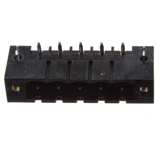


 工商网监
湘ICP备2023018690号
工商网监
湘ICP备2023018690号
