BK16-200-SZ
制修订履历表
版本 页码
A0
日期
制修订内容
1-8 2019-02-21
类
别
核准
新制订
签收日期
审核
制修订人
覃汉满
执行日期
主管签名确认
外发回签栏
Revision:PPTC-BK16-200-SZ-001(A0)
www.brightking.com
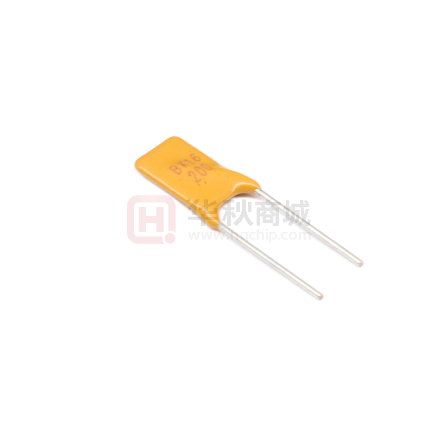
�BK16-200-SZ
Positive Temperature Coefficient (PTC) Data Sheet
Description
This model provides radial resettable overcurrent protection with holding current 2.0A. This model is suitable
for applications with higher working voltage up to 16V.
Features
■
■
■
■
■
■
■
Radial leaded devices.
Over-current protection
High voltage surge capabilities
Flame retardant epoxy polymer insulating material meets UL94 V-0 requirement.
Available in lead-free version.
Meets MSL level 1, per J-STD-020
Operating Temperature: -40℃~+85℃
Applications
■ Powered supplies
■ Industrial controls
■ Automotive electronics control
module protection
■
■
■
■
Security systems
Low voltage telecom equipment
Intelligent appliance
Power supply
Part Number Code and Marking
BK
16 -
Lead Shape
Z=Straight
Body Shape
S =Square
Holding Current Rating
Voltage Rating
Brand BK
Revision:PPTC-BK16-200-SZ-001(A0)
www.brightking.com
�BK16-200-SZ
BK 16
Brand BK
Voltage Rating
XXX
Holding Current Rating
Dimensions (Unit: mm)
A
D
B
E
F
C
SZ
Part
Number
A
B
C
D
E
F
Max.
Max.
±0.6
Max.
Typ.
Min.
BK16-200
6.5
12.5
5.1
3.0
0.6
4.6
SZ
Style.
Electrical Characteristics
Part
Number
IH
IT
VMAX
IMAX
RMAX
RMIN
Pd typ.
(A)
(A)
(VDC)
(A)
(Ω)
(Ω)
(W)
BK16-200
2.0
3.4
16
40
0.130
0.04
2.0
·IH = Hold current: maximum current device will pass without tripping in 25℃ still air.
·IT = Trip current: minimum current at which the device will trip in 25℃ still air.
·VMAX = Maximum voltage device can withstand without damage at rated current.
·IMAX = Maximum fault current device can withstand without damage at rated voltage.
·RMAX = Maximum resistance of device in initial (un-soldered) state.
·RMIN = Minimum resistance of device in initial (un-soldered) state.
·Pd typ. = Typical power dissipation from device when in the tripped state at 25℃ still air.
Revision:PPTC-BK16-200-SZ-001(A0)
www.brightking.com
�BK16-200-SZ
Polymeric PTC Selecting Guide
■ Determine the following operating parameters for the circuits:
·Normal operating current (Ihold)
·Maximum interrupt current (Imax)
·Maximum circuit voltage (Vmax)
·Normal operating temperature surrounding device (min℃/max℃)
■ Select the device from factor and dimension suitable for the application
■ Compare the maximum rating for Vmax and Imax of the PPTC device with the circuit in application and make sure
the circuit’s requirement does not exceed the device rating.
■ Check that PPTC device’s trip time (time-to-trip) will protect the circuit.
■ Verify that the circuit operating temperature is within the PPTC device’s normal operating temperature range.
■ Verify that performance and suitability of the chosen PPTC device in the application.
! WARNING
■ Mechanical Stress
·PPTC devices will undergo a thermal expansion during fault condition. If PPTC devices are installed or placed in an application
where the space between PPTC devices and the surrounding materials (e.g., covering materials, packaging materials, encapsulate
materials and the like) is insufficient, it will cause an inhibiting effect upon the thermal expansion. Pressing, twisting, bending and
other kinds of mechanical stress will also adversely affect the performance of the PPTC devices, and shall not be used or applied.
■ Chemical Pollutants
·Silicone-based oils, oils, solvents, gels, electrolytes, fuels, acids, and the like will adversely affect the properties of PPTC devices,
and shall not be used or applied.
■ Electronic and Thermal Effect
·PPTC devices are secondary protection devices and are used solely for sporadic, accidental over-current or over-temperature
error condition, and shall NOT be used if or when constant or repeated fault conditions (such fault conditions may be caused by,
among others, incorrect pin-connection of a connector) or over-extensive trip events may occur.
·PPTC devices are different from fuses and, when a fault condition occurs, will go into high-resistance state and do not open
circuit, in which case the voltage at such PPTC devices may reach a hazardous level.
·Operation over the maximum rating or other forms of improper use may cause failure, arcing, flame and/or other damage to
the PPTC devices.
·Conductive material contamination, such as metal particle, may induce shortage, flame or arcing.
·Due to the inductance, the operation circuits may generate a circuit voltage (Ldi/dt) above the rated voltage of PPTC devices,
which shall not be used under such circumstances.
■ General
·Customers shall evaluate and test the properties of PPTC devices independently to verify and ensure that their individual
applications will be met.
·The performance of PPTC devices will be adversely affected if they are improperly used under electronic, thermal and/or
mechanical procedures and/or conditions non-conformant to those recommended by manufacturer.
·Customers shall be responsible for determining whether it is necessary to have back-up, failsafe and/or fool-proof protection
To avoid or minimize damage that may result from extra-ordinary, irregular function or failure of PPTC devices.
·Any and all responsibilities and liabilities are disclaimed if any item under this notice of warning is not complied with.
Revision:PPTC-BK16-200-SZ-001(A0)
www.brightking.com
�BK16-200-SZ
Thermal Derating Curve
Percentage of Rated Current
200.00
150%
100%
50%
0%
-40.00
0.00
40.00
80.00
Device Ambient Temperature (℃)
Thermal Derating Chart – IH (A)
Maximum Ambient Operating Temperatures (℃)
Part
Number
-40
-20
0
25
30
40
50
60
70
85
BK16-200
2.94
2.66
2.40
2.0
1.87
1.74
1.60
1.40
1.26
0.94
Test Procedures and Requirement
Items
Test Conditions
Accept/Reject Criteria
Resistance
In still air @25℃
Rmin ≤ R ≤ Rmax
Time to Trip
Specified current, Vmax, 25℃
T ≤ max. Time to trip (Ttrip)
Hold Current
30 min, at IH
No trip
Trip Cycle Life
Vmax, Imax, 100 cycles
No arcing or burning
Trip Endurance
Vmax, 24hours
No arcing or burning
Revision:PPTC-BK16-200-SZ-001(A0)
www.brightking.com
�BK16-200-SZ
Typical Time-to-Trip Charts @25℃
Time to Trip (s)
100
10
1
0.1
0.01
0.001
10
1
100
Fault Current (A)
Storage Recommendations
■
■
■
■
Storage Temperature: -10℃~+40℃
Relative Humidity: ≤80%RH
Keep away from corrosive atmosphere and sunlight.
Period of Storage: 1 year.
Wave Soldering Recommendation Parameters
300
Soldering
3~5s
Temperature (℃)
250
245℃~260℃
200
150
100℃~130℃
100
Cooling
50
0
0
50
100
150
200
Time (s)
Items
Pre-Heating Zone
Soldering Zone
Cooling Zone
Conditions
Refer to the condition recommended by the flux manufacturer.
Maximum ramping rate should not exceed 4℃/sec.
Maximum solder temperature should not exceed 260℃
Forced cooling
Revision:PPTC-BK16-200-SZ-001(A0)
www.brightking.com
�BK16-200-SZ
Manual Soldering Recommendation Parameters
Items
Conditions
Soldering condition
The highest power of the manual soldering iron should be 30W or less, soldering
temperature should not be higher than 280℃.
Soldering time
The soldering time should be kept within 3 seconds, otherwise it might cause
insulation layer cracking, and increased part resistance.
Soldering position
The distance on the leads between the soldering point and bottom of the PPTC
body should be equal or greater than 4mm.
Other
The soldering iron should not contact the PPTC body except the leads. If the
soldering conditions are kept to lower temperature, less time and larger distance,
the outcome of the soldering will be better.
Notes: 1. Before using the device must be stored in the original bags, if the storage conditions do not guarantee,
the device may not be able to meet the given value.
2. The devices can’t used for reflow soldering.
Mechanical Characteristics
Items
Specifications
Test Conditions/Methods
Tensile strength
No visible damage
1.0Kgf, 10 seconds
Bending strength
No visible damage
0.5Kgf, 90°, 3 times
Vibration
No visible damage
Freq: 10-55Hz, Amp: 0.75mm, 1min
Reliability Test
Items
Specifications
Solder ability
No visible damage,Solder OK,
Solder area ≥95%
245±5℃, 2±1s, dipping depth=0.5inch max
from the body
Resistance to
soldering heat
No visible damage,
Electrical OK, │△R/R0│≦50%
260±5℃, 10+2/-0s
Damp heat,
steady state
No visible damage, Electrical OK,
│△R/R0│≦20%
40±2℃, 90~95 % RH, total 48Hrs, after 4Hrs
test electrical parameter
Temperature
cycling
No visible damage, Electrical OK,
│△R/R0│≦20%
Ta=-10+0/-1℃ 30min, Ta=70+1/-0℃ 30min,
5cycles, after 1hr test electrical parameter
Revision:PPTC-BK16-200-SZ-001(A0)
Test Conditions/Methods
www.brightking.com
�BK16-200-SZ
Packaging
Bag& Inner Box
0m
m
Label
200mm
Quantity
150mm
Revision:PPTC-BK16-200-SZ-001(A0)
16
65mm
500pcs/bag
2000pcs/box
253mm
www.brightking.com
�